
Abstract
Outdoor surveillance and security robots have a wide range of industrial, military, and civilian applications. In order to achieve autonomous navigation, the LiDAR-camera system is widely applied by outdoor surveillance and security robots. The calibration of the LiDAR-camera system is essential and important for robots to correctly acquire the scene information. This article proposes a fast calibration approach that is different from traditional calibration algorithms. The proposed approach combines two independent calibration processes, which are the calibration of LiDAR and the camera to robot platform, so as to address the relationship between LiDAR sensor and camera sensor. A novel approach to calibrate LiDAR to robot platform is applied to improve accuracy and robustness. A series of indoor experiments are carried out and the results show that the proposed approach is effective and efficient. At last, it is applied to our own outdoor security robot platform to detect both positive and negative obstacles in a field environment, in which two Velodyne-HDL-32 LiDARs and a color camera are employed. The real application illustrates the robustness performance of the proposed approach.
Introduction
Outdoor surveillance and security robots are widely used to implement desired tasks without human guidance in certain environments, such as public area patrol, border control, anti-terrorism, mine monitoring, sea area patrol, event security, and so on. 1 –4 In order to implement the above tasks, robots are commonly required to have the function of autonomous navigation. In order to navigate more safely, multiple sensors are usually employed together on the surveillance and security robot to acquire the scene information. Typical sensors are cameras, LiDARs, IMUs, and so on. For instance, camera sensor provides rich color and feature information. On the other hand, with recent advancements in technologies, LiDAR sensors are more and more popular to be applied to provide much accurate distance information. 5– 7 Thus, sensor fusion technology has been greatly researched in the field of robotics and computer vision for autonomous navigation, object recognition, posture estimation, and so on.
For outdoor surveillance and security robots, the more environmental information they perceived, the better they would navigate and implement tasks. 8 As analyzed above, both camera and LiDAR have their own advantages. One common way for outdoor surveillance and security robots is that both camera and LiDAR are fixed on the robot platform and the information that different sensors collected are fused according to some algorithm.
In order to achieve the information fusion of different kinds of sensors, the calibration between sensors is the first and most important prerequisite. Lots of algorithms for calibration between camera and LiDAR have emerged in decades. 9 –12 The core task of calibration is to build the relationship between 2-D points on the image and 3-D points on the point cloud. However, manually establishing correspondences for their mapping relationship is laborious and inaccurate because it requires multiple matches. Therefore, many methods have been put forward to solve this problem by using kinds of checkerboard or other tools. For instance, a special designed calibration between camera and LiDAR was introduced by Gong et al. 13 ; an ordinary box was employed by Pusztai and Hajder 14 ; a polygonal planar board was applied by Park et al. 15 Furthermore, several automatic extrinsic calibration algorithms were also proposed. 16,17 For example, the reflex value generated by the LiDAR and the gray-scale intensity value generated by the camera, which were automatically detected, were employed to calibrate the relationship between those two sensors by Pandey et al. 18 Besides, the idea of camera motion estimation by using sensor fusion odometry was adopted by Ishikawa et al. 19 to get the calibration between two sensors automatically.
This article also proposes a calibration approach for building the relationship between camera sensor and LiDAR sensor, which are fixed on an outdoor surveillance and security robot platform. Compared with these traditional algorithms mentioned above, the main idea of the proposed approach is that the calibration can be achieved by two independent steps successively: firstly, calibrating the camera (or LiDAR) coordinate into the robot platform coordinate (or an arbitrarily fixed coordinate); secondly, building the relationship between the camera and the LiDAR through the robot platform coordinate (or the predefined coordinate). This approach is easy to implement and needs no external cost, since both the calibration of camera and the calibration of LiDAR are essential once these two sensors are fixed on the robot platform. The proposed approach is applied on our own outdoor surveillance and security robot platform (Figure 1) to detect both positive and negative obstacles in field environment, and experimental results illustrate its effective and efficient performance.

The proposed approach is applied on our own outdoor surveillance and security robot platform to calibrate the following sensors: two compact HDL-32 LiDARs are mounted on the two sides of the platform top, and a color camera is mounted on the middle of the platform front.
The remainder of this article is organized as follows. The second section reviews some related algorithms of calibration between the camera and the LiDAR. In the third section, a mathematical model of the proposed approach is deduced, and some details of the approach are described. In the fourth section, experimental results show that the introduced approach is robust and stable. The fifth section concludes the article.
Related work
Calibration of LiDAR-camera systems for robotics has been widely studied in decades. 13,14,18 The core of the calibration is to build the relationship between the coordinates of the two sensors. In general, the main idea of these emerged algorithms is that a series of corresponding pairs of points, or lines, or other features are chosen manually or automatically. Then, the relationship between the coordinates of the two sensors can be solved by calculating the nonlinear least squares (NLS) problem of these corresponding pairs. These existed algorithms can be broadly classified into two categories: one that needs the calibration tool and one that does not need the calibration tool.
Algorithms that need the calibration tool
In the work of Gong et al., 13 a special object or likeness scene was required for their algorithm, since planar constraint of these three sides was used in its calibration process. The relative transformation between the two sensors was changed into the result of a NLS problem. In that paper, two kinds of sensors were required to be individually calibrated in each configuration firstly.
Similar work was carried out by Pusztai and Hajder, 14 in which a cardboard box was applied to implement their calibration. The size of the box was measured manually and carefully in advance. During the calibration process, three sides of the box should be clearly visible both in point cloud and in image. As the paper mentioned, the point cloud can be heavily affected by noise when it detects three planes. Thus, in their algorithm, the step of outlier removal is essential.
In the study by Li et al., 20 a special right-angled triangular checkerboard was designed to find the edges of the checkerboard in point cloud, and the corresponding edges in image were also detected by edge detection algorithm. Similarly, a special polygonal planar board was used as the calibration tool by Park et al. 15 and a plane with a triangular hole was used as the calibration tool by Ha. 21
Geiger et al. 22 also presented a toolbox with web interface for fully automatic camera-to-camera and camera-to-LiDAR calibration. According to their method, several checkerboards were placed all over the room, with different directions. Features of checkerboards are detected by the camera and LiDAR, respectively, and the features captured by the two sensors were matched. The biggest advantage of this article is that its checkerboard corner detector algorithm is significantly better than other algorithms.
Similar method was introduced by Wang et al. 23 Wang et al. 23 also employed a normally printed chessboard for calibration. The proposed method was based on the 3-D corner estimation of the chessboard from the sparse point cloud generated by one frame scan of the LiDAR. To estimate the corners, it formulated a full-scale model of the chessboard and fitted it into the segmented 3-D points of the chessboard. The model was fitted by optimizing the cost function under constraints of correlation between the reflex intensity of laser and the color of the chessboard patterns. Once the corners of the checkerboard in the 3-D point cloud were estimated, the extrinsic calibration of the two sensors was converted to a traditional 3D–2D matching problem.
Unlike other works which required at least three checkerboard poses, Zhou et al. 24 reduced the minimal number of poses to one by combining 3-D line and plane correspondences. Thus, only one checkerboard was required in their method. Besides, it is also considered that parallel planar targets with parallel boundaries provided the same constraints in their algorithm.
Algorithms that do not need the calibration tool
The idea of the algorithms that do not need the calibration tool is usually as follows: Firstly, some features are designed and extracted manually or automatically from both camera data and LiDAR data in the natural scene. Secondly, those extracted features are manually or automatically used to establish the corresponding relationship between camera data and LiDAR data. Finally, the relative transformation between these two sensors is changed into the result of a NLS problem according to the corresponding relationship of those features.
A data-driven automatic extrinsic calibration method was presented by Pandey et al. 18 The main idea of this article is that under the correct rigid-body transformation, the correlation between the LiDAR reflectivity and camera intensity was maximized. The surface reflectivity values reported by the LiDAR and the gray-scale intensity values reported by the camera were employed to calibrate the modalities of the two sensors.
In the study by Zachary Taylor and Johnson, 17 the orientations of gradients formed from the two candidate sensors were employed, and the sensor’s extrinsic parameters were obtained by minimizing the misalignment of the gradients. Thus, in this article, the calibration problem was changed into the minimalism problem between the orientations of gradient maps of the two sensors.
Another automatic extrinsic calibration of a camera-LiDAR system was mentioned by Irie et al. 25 : a dependence estimator called bagged least-squares mutual information was described to address the calibration parameter between two sensors. Their algorithm had two parts: a kernel-based dependence estimator and the noise reduction by bootstrap aggregating, which can handle richer features and robustly estimate dependence. It is thought that their algorithm would overcome drawbacks of outdoor environment, such as noise and non-smoothness.
A motion estimated algorithm by sensor fusion was introduced by Ishikawa et al., 19 in which the calibration process also needed no-special calibration tool and could be implemented automatically. The proposed method only required the 3-D point cloud and the camera image and did not need other information such as reflex of LiDAR and the initial extrinsic parameter.
Taylor et al. 16 also presented a camera-LiDAR calibration method that required no markers to be placed in the scene. In this method, both the intensity data from LiDAR and the images from camera were processed into orientation magnitude map. According to the camera model, LiDAR scan map was projected onto the camera’s map. Particle swarm optimization was used to find the optimal parameters for this model.
Unlike the above mentioned papers, this article gives up the traditional algorithms to calibrate LiDAR and camera. Instead of finding corresponding points in two coordinates, the proposed approach firstly calibrates the camera (LiDAR) coordinate into the robot platform coordinate (or a predefined fixed coordinate), then calculates the relationship between the camera coordinate and the LiDAR coordinate through the robot platform coordinate (or the predefined fixed coordinate). Experimental results show that the presented approach is effective and robust.
The description of the proposed approach
Theory and basic equations
What we will discuss in this article is the calibration of the extrinsic parameters of LiDAR and camera. Camera and LiDAR are mounted commonly as shown in Figure 2. The relationship between two coordinates can be presented by equation (1)
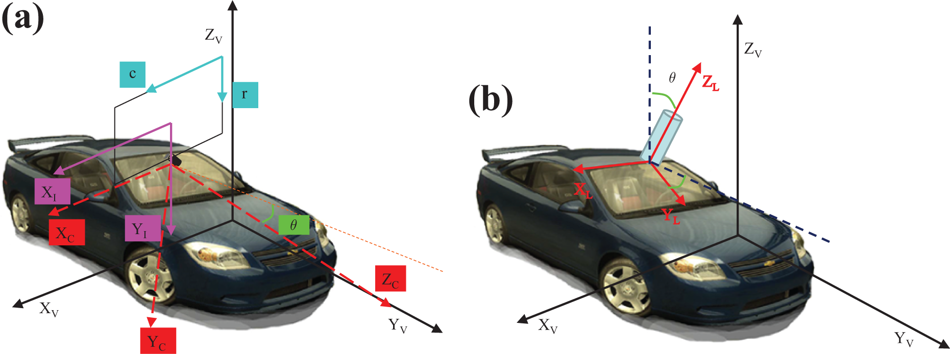
(a) The relationship between image coordinate and robot platform coordinate; (b) the relationship between LiDAR coordinate and robot platform coordinate.
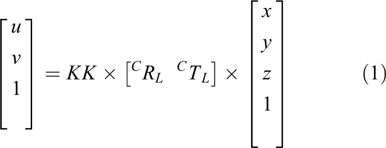
where
In traditional methods, a series of corresponding points are detected manually or automatically both in image and in LiDAR data, which are used to calculate R and T according to equation (1). Furthermore, this problem can be solved by changing it into equation (2), a general cost function as follows

where P is the projection operation from 3-D to 2-D in image coordinate, X represents points in LiDAR coordinate, and x represents points in image coordinate.
On the other hand, this problem in equation (1) can be divided into two independence parts, which are represented by equation (3) and in equation (4)

Equation (3) is a classical problem of camera’s calibration to the robot platform coordinate, when a camera is fixed on a robot platform.

Equation (4) is the expression of mapping LiDAR coordinate into robot platform coordinate, in which
In the application of our outdoor surveillance and security robot platform, it is found that the relationship between LiDAR and camera is fixed once they are mounted on the platform. Thus, the calibration can be generally undertaken only once, and the parameters will not change anymore. Unlike many previously reported methods, the approach proposed in this article first calibrates the two sensors independently according to equations (3) and (4), and then builds the relationship by combining these two equations.
Approach description
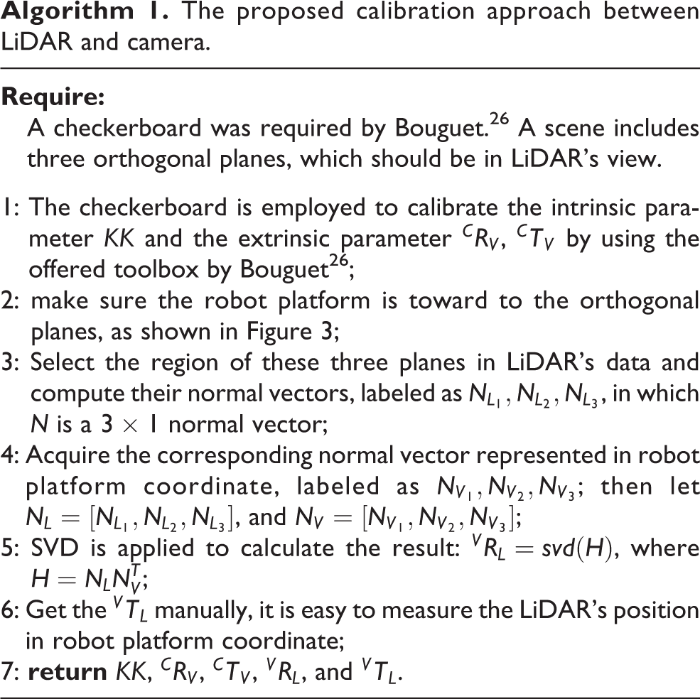
The calibration of camera is well researched, and many open source calibration tools are public. In our application, a classical calibration toolbox proposed by Bouguet. 26 is employed in our approach, which is mainly used to calibrate both intrinsic parameter and extrinsic parameter of the camera to achieve the equation (3). Calibration methods for LiDARs are also widely researched, 27 –29 and we expand our previous work 30 to the implementation of the calibration in this application. The proposed algorithm is described as in Algorithm 1.
The proposed calibration approach between LiDAR and camera.


The process to calibrate LiDAR coordinate into the robot platform coordinate.
Thus, input the parameter of

When the parameter
Experimental results and analysis
In order to evaluate and verify the proposed approach, experiments are designed and carried out both in indoor environments and field environments. Outdoor experiments are composed of three parts: first, a test of indoor qualitative analysis is carried out to verify the proposed approach; second, a series of experiments, where LiDAR and camera are under different poses are designed to quantitatively analyze the accuracy of the proposed approach, which is compared to the state of the art; at last, the proposed approach is applied on our own outdoor surveillance and security robot platform for calibrating the relationship among two LiDARs, a camera and the robot platform itself. The outdoor robot platform is employed to detect both positive and negative obstacles in field environment, and the results show the proposed approach is effectiveness.
Indoor qualitative analysis
A special platform, as shown in Figure 4(b), which can be rotated around two axes is designed specially to carry out our experiments. A Velodyne HDL-32 LiDAR is mounted on the platform, and a camera is also mounted beside the LiDAR. The platform is mounted on a shelf, which is used to instead of a robot platform (Figure 4(a)), and a camera is also mounted beside the LiDAR. Indoor room environment is chosen, since there are three orthogonal planes: ground and two orthogonal walls (Figure 4(c)) to support the proposed calibration approach. A box is placed in front of the platform to check the accuracy of the calibration (Figure 4(c)). A checkerboard is also employed to calculate both the intrinsic parameter and the extrinsic parameter of the camera.

Platform of our indoor experiments. (a) The indoor scenario, in which a shelf simulated as a robot platform is placed and a camera and a LiDAR are mounted on it. A box is placed in front the robot platform to show the corresponding relationship between the LiDAR and the image; (b) a special designed platform that LiDAR is fixed on it, the platform can be rotated around two different axes. (c) The indoor scenario that three orthogonal planes are existed for the proposed approach, and a checkerboard is also placed for calibrating both the intrinsic parameter and the extrinsic parameter of the camera.
According to the proposed approach, the calibration is composed of two parts: the calibration of LiDAR coordinate to robot platform coordinate (according to equation (4)) and the calibration of camera coordinate to robot platform coordinate (according to equation (3)). The checkerboard is employed to calibrate both the intrinsic parameter and the extrinsic parameter of the camera according to the study by Bouguet. 26 The process of calibrating the LiDAR is described in Algorithm 1, in which three orthogonal planes are employed to improve the accuracy. Some typical results of mapping LiDAR’s data into the image are shown in Figure 5.

(a to e) Some typical results that mapping the LiDAR data of the person and the box into the image to show the effectiveness of the proposed approach.
In order to show the accuracy more clearly, only those LiDAR points, which are located on the person, the checkerboard and the box are mapped into the image in Figure 5. From Figure 5, it is obvious that the proposed approach is effective.
Indoor quantitative analysis
Thanks to our special platform, which can rotate around two axes, many groups of data sets generated by LiDAR under different poses are collected, indicating different relationships between LiDAR and camera, and verifying the robustness and the accuracy of the proposed calibration approach. Among these groups of data sets, four groups that are obtained by the LiDAR under several typical poses are chosen to quantitatively analyze the proposed approach. Figure 6(a) shows these four poses of the equipped LiDAR. From top down, the first pose shows the LiDAR is vertically equipped (labeled as Scene1). The second pose shows that LiDAR rotates around X-axis (labeled as Scene2). The third and the forth poses show that LiDAR is rotated around both X-axis and Z-axis (labeled as Scene3 and Scene4). Figure 6(b) shows the original point cloud data of the LiDAR corresponding to these scenes. During the process, the pose of camera is kept unchanged.

Experiment results under four typical poses between the LiDAR and the camera. (a) Four scenes that the LiDAR is rotated in different poses while the camera is kept unchanged. (b) The original point cloud in LiDAR coordinate. (c) The LiDAR data that located on the box under different poses. (d) The mapping result in image of those LiDAR data.
The experiment in this part is designed as follows: the pose of camera is kept unchanged, and four different poses of LiDAR are rotated and labeled as

Quantitative analysis to estimate the accuracy of mapping LiDAR data into image.
The results of this experiment are shown in Figure 6(d) and are compared with the state-of-the-art algorithm presented by Unnikrishnan and Hebert 9 is employed for comparison. The comparison results are listed in Table 1. Compared with the state-of-the-art algorithm, the proposed approach has higher calibration accuracy and easier operation, since it acquires at least nine different poses of planes to achieve a good result according to the study by Unnikrishnan and Hebert, 9 but only three orthogonal walls are needed.
The quantitative analysis of the calibration compared with the study by Unnikrishnan and Hebert. 9
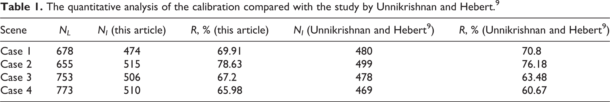
In Table 1, it is found that the NI is much smaller than NL both in our approach and in the compared one. The main reason is that the bottom of the box is out of the image.
Outdoor real application
The proposed calibration approach has been applied in our own outdoor surveillance and security robot platform (shown in Figure 1). The task of our outdoor surveillance and security robot platform is to patrol and monitor the field area. There are various positive obstacles and negative obstacles on the patrol road. In order to achieve the safer autonomous patrol, both positive obstacle detection and negative obstacle detection is necessary. Thus, the LiDAR-camera system fixed on our outdoor surveillance and security robot platform is mainly used for detecting those positive and negative obstacles in field environment. As we know, the patrol roads in field environment are bumpy. Besides, sensors work under different rates. Therefore, it is a test for the calibration effectiveness of the robot platform when it drives on such a bumpy road.
There are two Velodyne HDL-32 LiDARs mounted on the two sides of the top of the robot platform, and a camera mounted on the middle of the robot platform front as shown in Figure 1. These LiDARs and camera are employed to find positive and negative obstacles in field roads. Thus, the relationship between those sensors are prerequisite and important. In this application, the LiDAR-camera system, the LiDAR-robot platform system, and the camera-robot platform system are calibrated accurately by the proposed approach. Figures 8 and 9 show the experimental results. In order to display the corresponding points more clearly, only these LiDAR points that of potential negative obstacles are mapped into image to verify the correctness.

(a to c) Typical field experimental results show the calibration of the proposed algorithm is effective in different scenes (I).

(a to c) Typical field experimental results show the calibration of the proposed algorithm is effective in different scenes (II).
In those experimental results, to show the corresponding relationship more clearly, four parts are presents in the interface window. They are (from left to right) LiDAR coordinate map, grid map in robot platform coordinate, the control platform, and image coordinate map. The detected obstacles are marked both in the LiDAR map, the grid map, and the image map according to their relationship. The results indicate that these three coordinates are well calibrated, since all of these obstacles are painted correctly. The distance between the robot platform and the obstacle at the current moment is also marked beside the obstacle to show the accuracy of the calibration results. Experimental results illustrate the high performance of the proposed calibration approach.
Conclusion
This article introduces a fast calibration approach for LiDAR-camera system. The theory and mathematical equations of the relationship among LiDAR, camera, and robot platform are deduced. On this basis, this article proposes a fast approach that combines two independent calibration processes, which are the calibration of LiDAR and the camera to robot platform, so as to build the relationship between LiDAR and camera. A novel approach to calibrate LiDAR to robot platform is applied to improve the accuracy. Indoor and outdoor experiments are both carried out to verify the effectiveness and robustness. Finally, the proposed approach is applied on our own outdoor robot platform to detect negative obstacles in field environment. Two Velodyne HDL-32 LiDARs and a camera are used on the robot platform to detect negative obstacles. The relationship between these three sensors and the robot platform are established by the proposed approach. Both indoor experiments and outdoor real application illustrate the effective and efficient performance of the proposed approach.
Footnotes
Declaration of conflicting interests
The author(s) declared no potential conflicts of interest with respect to the research, authorship, and/or publication of this article.
Funding
The author(s) disclosed receipt of the following financial support for the research, authorship, and/or publication of this article: This work was supported in part by the National Natural Science Foundation of China under grant 61803380,61790565.