
Abstract
Automation is a process of handling and transport of products, which allows replacing man’s control by operation of manipulators and robots. It represents a highly complex process, which includes several operations and they are usually performed automatically by particular devices. In this article, a technical design of a universal versatile robotic manipulator for handling with automotive products is presented. The designed device is intended for handling with automotive products with a maximum weight of 25 kg. The technical solution of the manipulator comes from required specifications and operation conditions given by the customer, who will install it as a part of an automatic line. A particularity of the manipulator is the special functionality, which allows handling with objects of both circular and angular shapes. This is ensured by adaptable gripping fingers, which are able to adjust their position by means of a well-considered mechanism. The technical design of the manipulator includes calculation of forces needed for reliable gripping of manipulated objects, choice of a working screw and calculation of the load and carrying out of strength analyses of the main loaded part of the manipulator. Based on results, there is recommended an appropriate material for the manufacture of the device to reach its optimal accuracy of positioning of handled objects during a long-term operation.
Keywords
Introduction
One of the most important roles of engineers is analysing the existing and newly designed work processes in order to find an optimal way to perform effective operations. Nowadays, various methods and approaches are applied in the process of development, design and production of machines and their subsystems. 1,2 Inter alia, they comprise computational simulations allowing the identification of structural and dynamic properties by means of tools of virtual reality. 3,4
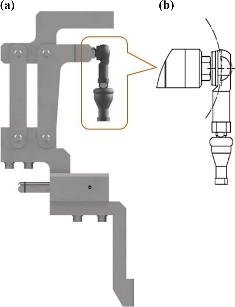
The designed robotic manipulator (Figure 1(a)) will be part of an automatic line (Figure 1(b)). Function of the manipulator is loading movable containers with manufactured products for automotive industry. Handling with materials and products in the automotive industry is an activity, which requires the use of suitable operations methods for the transportation of a given quantity of material to a specified location in a short time as possible. Further, it has to be performing in a certain order together placing into a right position and at the lowest cost. A system of handling machines responses for transfer of materials between prescribed workplaces with the minimal number of obstacles and it interconnects these workplaces and workshops. 5 –7 As handling process of materials can be dangerous, especially in the case of storing and moving large and heavy products. Generally, hundreds to thousands of tons of material and products are produced and handled every day. It requires the coordination of a large number of operation processes. Achievement of the most effective system of manipulation processes significantly improves the competitiveness of the product by diminishing the handling costs.

An assembly of the designed manipulator (a) and its placing on an automatic line (b).
There is a possibility to trace in every area of industry the devices and machines for transport and handling of products. Basically, each process of production of any kind of product comprises quite a large number of minor operations. These operations are realized using devices for transport and handling, among those industrial robots also belong. They represent an integral part of the process of automation. 8,9
As known, the process of automation includes a number of very simple control operations, which are usually done automatically by means of a relatively simple device, as well as by means of complicated control of large-size production units. Control is a process, which evaluates and precesses information related with a controlled object. It usually includes measumements of device parameters and data and signalization of equipment states. Based on evaluated data, processes are performed in such a manner, that the prescribed task is reached. The described requirements are the initial goal for the design of the robotic manipulator.
Specifications of parameters of the robotic manipulator
Simple control, possibility of its controlling by an operator and compatibility with an operation system are the essential demands given for the robotic manipulator. The maximum load capacity of the mechanism is of 25 kg. The mechanism contains three fingers, which ensure the gripping of a transported product. The needed gripping force results from the fact that products are gripped only by friction between the object and the fingers. 7,10 The mechanism contains two subsystems, which are actuated by a designed appropriate electric motor. 11 One subsystem actuated one finger, which has only one degree of freedom and other two fingers are actuated by the other subsystem. 12 Range of operation of the finger is from 0° up to 60° depending on the size of the transported product. Additionally, when the shape of the load is changed, the operation range is of 1.05 rad. Considering the maximum gripping force, the length of a finger is of 150 mm, further, the maximum finger folding velocity is of 50 mm·s−1 and the finger rotation velocity is of 1.57 rad·s−1. Requirements for the designed robotic manipulator are summarized in Table 1.
Robotic manipulator requirements.

Design of a structure of the robotic manipulator and functional calculations
A specific functionality of the designed robotic manipulator is the possibility of gripping of circular objects (Figure 2(a)) and angular objects (Figure 2(b)). Figure 3 shows the main individual parts of the robotic manipulator.

Configuration of fingers when handling circular objects (a) and angular objects (b).

Main parts of the designed robotic manipulator.
Therefore, computation of the gripping force and the engine output corresponds to this requirement. 10 Table 2 contains values of the static and the dynamic sliding coefficients in contact of the fingers and a handled object. Independently of the type of sliding, the lowest value of the sliding coefficient is of 0.1, therefore, in further calculations, this value is taken into account (f = 0.1).
Static and dynamic sliding coefficients (f s and f d) for selected material of handled objects.

Figure 4 shows the scheme of distribution of the forces between two fingers and a transported object. The normal force F N corresponds to the fingers configuration for gripping an angular object and the normal force F n corresponds to the fingers configuration for gripping circular objects. A prerequisite of the reliable functionality of the manipulator has to ensure that the force F t between the object and the fingers must be greater (or equals) than the gravitational force of the handled object F g. If the weight of the handled object is m = 25 kg, the gravitational acceleration is g = 9.81 m·s−2 and the slip safety factor is k = 1.4 (−), the gravitational force of the object is calculated based on the following formulation

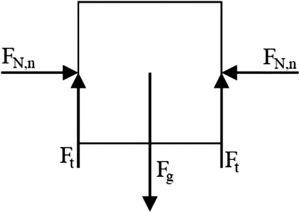
Distribution of the gripping forces on the gripped load.
After substituting the known values to (1), the friction force must be greater than the meet condition

Considering the sliding coefficient f, the necessary gripping force

After substituting the known values to equation (2), the gripping force is F N,n = 3440 N. When the robotic manipulator is reconfigured for gripping the object of circular shape, applying the method of a free body diagram the force F n is uniformly distributed by means of three components (Figure 5(a)), namely F n1, F n2 and F n3 and their values according to (3) are
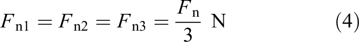

A free body diagram for gripping circular objects (a) and angular objects (b).
The required gripping force of each finger is calculated by the formulation (4) and the value is

This force ensures safe load handling. During gripping of objects of an angular shape, the same conditions of the friction force are valid, but the normal forces act in a different manner, as it can be seen in Figure 5(b). This situation is caused by the fact that the rotating fingers angle and lines of acting forces are in the same direction. There is necessary to mention, that the third finger acts as a reaction of two forces generated by two others rotating finger.
Considering the conditions of equilibrium of a body and friction force in the contact of fingers and the handled object are taken into account, the normal force, which acts on the most loaded finger (Figure 5(a), the non-rotating finger represented by the force F N1), is of F N1 = 1720 N.
When values of the gripping forces for both circular and angular objects are evaluated, the gripping of angular objects causes the greater force on the non-rotating finger in comparison with the gripping of the circular object. Therefore, all calculations have been performed for the gripping of both shapes of a handled object.
Kinematics of motion of the gripper manipulator shown in Figure 6(a) is ensured by a knuckle joint, which consists of a joint sphere with a thread. Kinematics of motion of the mechanism has to provide two degrees of freedom of the two active fingers. This specific motion is guaranteed by the application of the articulation. The vertical movement of the mechanism causes the curve motion 13,14 (Figure 6(b)), which is caused by the acceptable slope of a connecting ball with a thread. The manipulator uses two ball-joints with the working ranges of 40° and 25°.
A structural design of one robotic arm gripper (a) and a knuckle joint motion curve (b).
Suspension of the finger performing only vertical motion is realized by a screw connection and therewithal one degree of freedom is allowed.
Design of a working screwball
As the first step for the design of the working screwball, it is necessary to know the maximum value of the loading force. For this purpose, the axial force for the acting direction of the mechanism is calculated. Input data for calculation are represented mainly by the mechanism dimensions as following (Figure 7):
a = 82 mm,
b = 40 mm,
c = 120 mm,
d = 220 mm and
η = slide assembly efficiency, η = 0.96.

Geometry of the designed finger mechanism.
The sliding effect of the normal force F N1 = 1720 N is transmitted and subsequently distributed to the mechanism by means of two pins (Figure 7). Considering this fact there is assumed the equal distribution of the loads, which results in an equal load of each pin by the force of

which corresponds to the half value of the normal force F N1. However, the force F N1 involves a rotating effect within the mechanism as well. The generated moment has to be in the equilibrium with the twisting couple of the forces F 0. The value of the force F 0 is given as follows

Considering dimensions of the designed mechanism shown in Figure 7 and the requirement of the moment’s equilibrium, the following formulation is written

When values of variables are substituted in the formulation (8), the value of the gripping force needed for the handling of circular objects is F = 7131.7 N. The force F represents the friction force in the contact of the pin and the mechanism (Figure 7). Efficiency of the designed mechanism within the sliding friction is considered as η = 0.96. As the mechanism contains four moving pins, the total efficiency η c of the mechanism motion is calculated as follows

It follows the total force in the longitudinal axis of the working screw F v given as a sum of the forces of the individual fingers F v1, F v2 and F v3 has to overcome the losses due to the friction, which are of 15%. It is calculated as follows
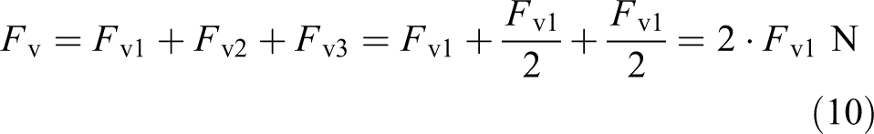
Substituting known values of individual variables, the total loading force acting in the longitudinal axis of the working screw is of

The reliable operation of the mechanism can be ensured only by the screw, which has a higher dynamic load rating than just computed values of the force F v. Additionally, the working screw has to meet the prerequisite of higher efficiency than the calculated efficiency (equation (9)). Therefore, the ball screw with the following parameters has been chosen: the maximum permissible dynamic load given by the working screw producer is F dyn = 27.5 kN, the thread effective diameter d 0 = 32 mm and the thread pitch t = 5 mm. The chosen working screw is shown in Figure 8.

The working screw.
Kinematics of the mechanism
The chosen working screw has to operate at the specific conditions. The object is being gripped with the manipulator fingers moving at a velocity of vx = 25 mm·s−1. The value of the velocity is the requirement of the manipulator producer. Revolutions of the screw have to ensure this velocity. As the manipulator uses a lever mechanism (Figure 9), the relation of velocity components in individual directions is given by the following formulation
where variables vx and vy are velocities of the arm movement in individual directions (Figure 9) and parameters a and c are dimensions of the arms, where a = 82 mm and c = 120 mm, respectively.

The lever arm of the designed mechanism: dimensions (a) and its cross-section (b).
Solving the formulation (12) results to the value of the velocity of

The chosen ball screw is shown in Figure 10.

The chosen ball screw.
Finally, using the value of the velocity vy , there is a possibility to quantify the proper number of revolutions of the screw. Its solution comes from the velocity vy of the screw and the screw pitch t = 5 mm

The required number of rotations of the screw needed for reliable operation is n = 3.4167 rps.
Multibody analysis of the robotic manipulator
A structure of the designed robotic manipulator was analysed in Simpack 9.10.1 multibody software in term of a comparison results of the analytical calculation presented above with values obtained from dynamic simulation. Created bodies of the device taking an important part in its dynamics have been imported to the Simpack 3D interface and the multibody model of the robotic manipulator has been setting up. The bodies of this multibody system are linked by means of joints and kinematic constraints allowing required relative motions and restricting others. The bodies themselves are rigid. The multibody system is completed by the definition of excitation in the desired joint element. The multibody model of the robotic manipulator considering in multibody simulations is shown in Figure 11.

A multibody model of the robotic manipulator.
The created multibody model of the robotic manipulator consists of rigid bodies with defined mass and inertia properties interconnected by means of joints elements defining degrees of freedom of individual bodies and by means of constraints restricting degrees of freedom of bodies’ couples. 15,16 Additionally, the model contains force elements, which define forces and torques in desired locations between bodies. The Simpack solver has converted such a structure of the multibody model into a set of nonlinear differential-algebraic equations. 17,18 Their explicit formulation is as follows

where

In dynamic simulations, the robotic manipulator has been gripping a circular object. Therefore, results from these analyses are compared with analytical results for gripping circular objects. Following figures show waveforms of dynamic and kinematic quantities, such as gripping force calculated in the contact 19 of manipulator fingers and the circular object, further velocities in joints of selected bodies as well as accelerations.
Figure 12(b) shows waveforms of the gripping force F n1, when the robotic manipulator is gripping a circular object (Figure 12(a)). From the graph, we can see a nonlinear course of the gripping force from the zero value up to the maximal gripping force of 1147.52 N. This value reached from the simulation corresponds with the value of the gripping force F n1 calculated analytically (equation (5)). The zero value of the F n1 force expresses the fact that fingers are not in contact with the gripped object and its waveform depends on the type of the contact formulation used in the MBS model.

A view of gripping of a circular object (a) and a waveform of the corresponding gripping force F n1 (b).
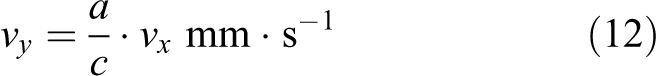
Farther, values of velocities vx and vy from simulation (Figure 13(a) and (b)) and analytical calculation (section ‘Kinematics of the mechanism’ and equation (13)) are compared. These quantities are measured in joints of the lever arm (Figure 9). Figure 13(a) shows the waveform of the velocity vx , which is identified in a longitudinal direction. This graph indicates a sinusoidal tendency of the velocity vx , whereby the maximal value is of 0.024949 m·s−1 = 24.949 mm·s−1, which coincides with the given value of the vx of 25 mm·s−1 (section ‘Kinematics of the mechanism’).
Waveforms of velocities vx and vy calculated in joints of the lever arm in compliance with Figure 9.
Similarly, the waveform of the velocity vy measured in the vertical direction has the sinusoidal tendency (Figure 13(b)). In this case, the identified maximal value is of 0.017124 m·s−1 = 17.124 mm·s−1. This value obtained from the simulation confirms the calculated value (equation (13)).
The working process of the gripping fingers is actuated and controlled by the working screw, which is loaded by the axial force F V presented above (Figure 7). This force acts in the vertical direction. Depending on whether the fingers are gripping an object or releasing, the force directs to one or opposite direction. Figure 14(a) shows the acting of this force in the multibody model of the manipulator. The waveform of the force F V is cyclic (Figure 14(b)) depending on the position of the working screw. The maximal value of this force calculated by means of the simulation calculation is of 16815.04 N (Figure 14(b)), which corresponds with the value obtained by the analytical calculation (equation (11)).The force F 2 identified in the pin connecting the lever arm and the finger is indicated in the horizontal direction (Figure 15(a)). The waveform of the force F 2 confirms its cyclic character (Figure 15(b)) during operation. When the analytically calculated value of the force F 2 (equation (6)) is compared with the maximal value 862.703 N obtained from the simulation (Figure 15(b)), it is possible to recognize the well conformity of both approaches.

A visual display of the force F V in a working screw (a) and a waveform of the force F V (b).

The force F 2 acting in a pin (a) and its time-dependent waveform (b).
Strength analysis of the most loaded part of the robotic manipulator
In the case of gripping of angular objects, the major deformation occurs on the effector (Figure 3), which is loaded by the asymmetrically acting moments from the individual fingers. Such a deformation significantly influences the accuracy of the manipulator in the operation process. 20 Therefore, the strength analyses of the effector have been the other important step in the design of the manipulator.
In the design process, two types of materials were selected, namely AW-6082 aluminium alloy and S355 steel. Each of them has certain specifics in term of mechanical properties, mass and inertia properties as well as price. While S355 steel is characterized by the yield strength of 340 MPa in comparison with AW-6082 aluminium alloy of 220 MPa, steel density is 2.9 times greater aluminium alloy, namely 7850 versus 2700 kg·m−3.
The strength analyses have been carried out in Ansys 17.2 program package working based on the finite element method. 21,22 The boundary conditions were defined for restraining degrees of freedom in x and y axes. A functionality Fixed Support was used for it. The movement of the effector in the z axis was allowed. Further, the maximum forces resulting from the fingers were applied to the effector structure. There was analysed the case for gripping of angular objects.
The size of finite element was set on the value of 1.3 mm to reach a sufficient accuracy of results. From results, displacement and deformation state of the effector and distribution of the von Misses stress were observed.
Figures 16, 17 and 18 show results of simulation computations of maximum displacement and maximum deformation of the effector and distribution of the stress overall its structure. There are results for both AW-6082 aluminium alloy (a) and for S355 steel (b).

The maximum displacement of the effector: AW-6082 aluminium alloy (a) and S355 steel (b).
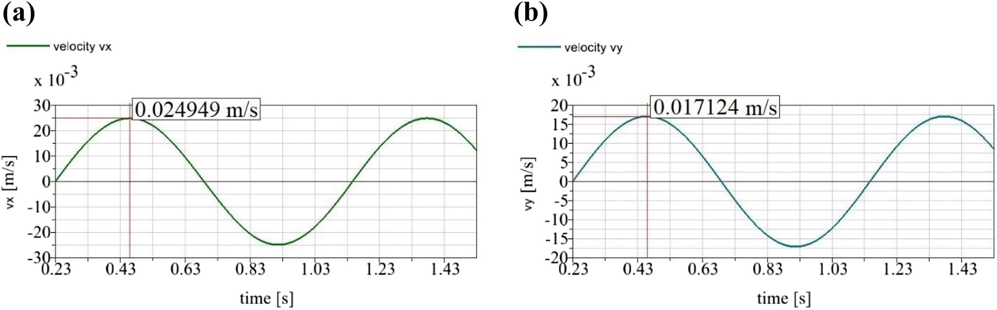
The maximum deformation of the effector: (a) AW-6082 aluminium alloy and (b) S355 steel.
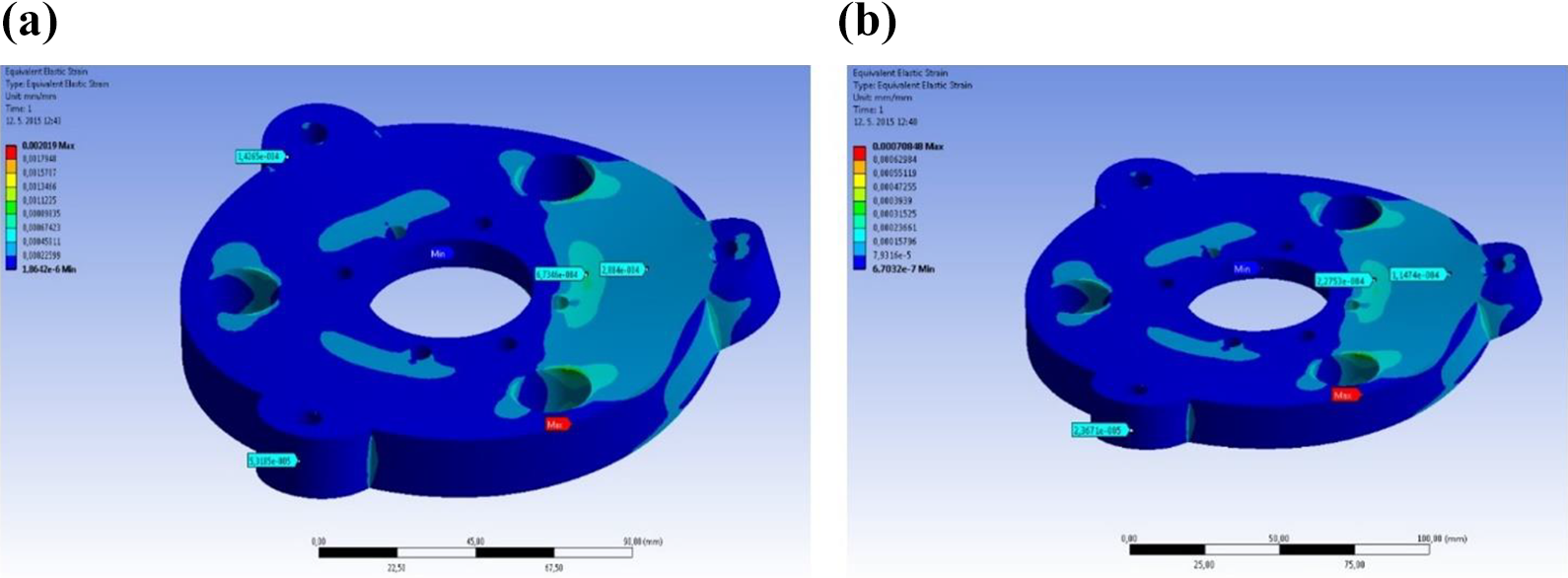
Distribution of the stress in the effector structure in compliance with von Misses hypothesis: (a) AW-6082 aluminium alloy and (b) S355 steel.
The maximum displacement of the effector was calculated in the location of connection of the effector with a screw on the perimeter (Figure 11). The plate made of AW-6082 material is bent of 0.129 mm and the plate made of S355 material of 0.045 mm.
When evaluating the maximum deformation of the effector (Figure 12), the aluminium alloy structure shows greater deformation than the structure of the plate made of the steel. The maximum deformation of the AW-6082 plate is of ε = 0.0021 and the maximum deformation of the S355 plate is of ε = 0.00071.
Finally, values of the von Misses stress in the plate structure were assessed (Figure 13). As it is identifying, the distribution of the stress within the structure for both materials is very similar. Values of the maximum stresses were compared with the yield of the strength of both chosen materials. The maximum value of the stress for the aluminium plate was calculated of σ max = 134.55 MPa and for the steel plate was calculated of σ max = 135.61 MPa. These values are safely below the yield strength of both materials.
Based on performed analyses, we have found out that from the strength of the structure, both materials could be used for the production of the effector. However, in term of accuracy of the manipulator operation, the steel plate is able to position handled objects within smaller values of errors due to smaller displacement and deformation of the plate structure during its operation.
Conclusion
The article presented a technical solution of the robotic manipulator intended for installation on an automatic line for the handling of products in the automotive industry. Design of the device took into account the number of requirements of its producer for ensuring reliable long-term operation with minimizing of failures even non-operating state. The designed robotic manipulator is able to handle a load of the maximum weight of 25 kg. It includes the special functionality, which allows gripping both circular as well as angular objects. Objects are gripped by three fingers, at which position of two fingers is adjustable by a designed mechanism. Calculation of forces acting in the device is a part of the technical design of the robotic manipulator. There are calculated mainly forces needed for safety gripping of an object by the fingers within considered friction conditions, further forces acting in the mechanism, which load its individual parts, such as bolts, pins, an effector and so on. Based on given requirements and calculated forces, a working screw ensuring the movement of the mechanism was chosen. Results of simulation computations performed by means of multibody model of the robotic manipulator have shown well conformity with results from analytical calculations. Moreover, there were performed strength analyses of the most loaded part of the mechanism, that is, an effector. In numerical calculations, two different materials were considered, namely AW-6802 aluminium alloy and S355 steel. Regarding the stress distribution in the effector structure, both materials are acceptable. From the accuracy point of view, there were observed, the plate structure made of aluminium alloy is more deformed as the plate structure made of steel. For the production of the effector, the steel is a more suitable material.
Footnotes
Declaration of conflicting interests
The author(s) declared no potential conflicts of interest with respect to the research, authorship, and/or publication of this article.
Funding
The author(s) disclosed receipt of the following financial support for the research, authorship, and/or publication of this article: This work has been supported by grant agency grant agency VEGA project No. 1/0073/19 and Slovak Research and Development Agency under the contract no. APVV-14-0096.