
Abstract
Currently, there is no effective detection and diagnosis technology for the frequently happened mechanical defects of disconnectors. A porcelain column high-voltage disconnector is taken as the object to study the influence of mechanical defects, including bearing jamming, axle pin jamming, and three-phase position asynchrony on the operating torque through geometric mechanics deduction. An operating torque detection technology is proposed, which could accurately measure the operating torque of the disconnector without destroying its original shafting. Using this technology, the operating torque curves of the disconnector in normal state and typical mechanical defect simulation states are measured and compared. The results indicate that the operating torque changes with the mechanical state of disconnector, and these changes could be quantified through the proposed detection technology. And the types of mechanical defects can be distinguished according to their different effects on the operating torque curve. Based on this, a practical mechanical defects diagnosis method is summarized to provide reference for maintainers to diagnose the mechanical defects of disconnectors.
Keywords
Introduction
Porcelain column high-voltage disconnector is mainly used to provide an electrical interval during the maintenance of electrical equipment, which is a clearly visible disconnect point to ensure the personal safety of maintainers. 1,2 Most porcelain column high-voltage disconnectors work directly in the outdoor environment, thus are subject to the erosion of wind, frost, rain, and snow. Besides, a few attention has been paid to the daily maintenance and repair due to their relatively simple structure and low cost, resulting in frequent faults and defects, 3,4 such as mechanical defects, 5 conductive loop overheating, 6 secondary circuit defects, 7 and insulator damage defect. 8 Among them, mechanical faults and defects are particularly severe. For example, according to Yunnan Power Grid Corporation in China, there are 143 mechanical faults and defects in the total 289 faults and defects of disconnectors for voltage greater than or equal to 110 kV from 2008 to 2014, accounting for 49.5% of the total.
At present, many studies focused on the detection of overheating of disconnectors and insulator damage defect. Infrared (IR) temperature measurement technology is commonly used for the detection of overheating. Carlos and Fortes used a camera with IR detection capability to identify thermal anomalies in substations and pointed out that the disconnectors and terminals between equipment are the most vulnerable points to thermal anomalies. 9 Lindquist and Bertling proposed a method to save and make use of thermography measurements to estimate statistical distribution parameters for the time to failure for a population of electrical contacts of disconnector. The method could provide useful reference for the assessment of the condition of high-voltage disconnector electrical contacts. 10 He et al. designed a passive wireless high-voltage disconnector temperature monitoring system, the power which needed is supplied by the inductive current, the wireless communication technology is used to improve the convenience of the system. As the temperature measurement device is installed near the contact, defects of abnormal heating could be discovered in time, which is of great significance for ensuring the safe operation and improving power distribution reliability. 11
For the detection of insulator damage defect, the most established technology is the ultrasound detection method, 12 other technologies include vibration technique, 13 ultraviolet (UV) imaging detection method, 14 pulse IR thermal wave technology. 15 Li et al. proposed a vibration-based damage detection method for porcelain insulators, and the method was verified useful. 13 Lei et al. applied UV imaging technology to the detection of insulator defects and successfully detected the damage defects on the insulator string, porcelain post insulator, and composite insulator. 14 Wang et al. proposed a nondestructive testing method based on pulsed IR thermography to test and evaluate the state of porcelain post insulators. More specifically, the sample was heated instantaneously by a high energy flash pulse while an IR camera monitors the changes of surface temperature. The defects of the insulator could be identified and qualified via IR thermal images sequence processing and analysis. 15
For the mechanical defect detection technology of disconnector, some work has been carried out by scholars. In substation, the detection of mechanical state of disconnector is mainly determined by experienced maintainers through the manual operation of disconnector and the observation of operation process. The diagnosis is related to the subjective experience and technical ability of the maintainers. 5,16 In order to quantify the operating torque, some methods were proposed, such as strain detection method 16 and manual operation torque detection method. 17 In the strain detection method, the strain gauge is attached on the operating shaft of the disconnector, the operating torque is measured according to the relationship between the strain and torque. 16 The method is feasible in theory, and the strain gauge is cheap. However, the experiment results are easily affected by the paste position of strain gauge and the external environment due to the sensitivity of strain gauge, resulting in low practical reliability. In the manual operation torque detection method, a force sensor was installed on the rocker handle to measure the operating force and multiply the force by the force arm to obtain the manual operating torque. 17 This method requires the operator to rotate the handle at a constant speed; however, it is difficult to keep the consistency of manual rotation speeds due to the changing of operating force. As a result, the repeatability of multiple measured curves in the same state is poor in practical applications, and it is impossible to judge whether the difference of torque is caused by the inconsistency of manual speed or the change of mechanical state of disconnector.
Typically, a disconnector can be operated either manually or by a motor, and the current of disconnector motor was used to judge the mechanical state by some scholars. The current method has been widely used in defects detection of motor 18,19 and circuit breakers. 20,21 A quadratic relationship between the motor output torque and the stator current exists when the excitation branch current of the motor is ignored. 22 Inspired by this, a method based on stator current was proposed to detect the mechanical defects of disconnector. 23,24 It was observed that the stator current waveforms of the driving motor change with the mechanical state of the disconnector. But this method has not considered the effect of power supply voltage fluctuations on the current.
Vibration detection method has been successfully applied to defects detection and diagnosis of circuit breakers. 25,26 Based on this, the vibration detection method has also been applied to the mechanical state detection of porcelain column disconnector. 27,28 Chen et al. proposed a multi-support vector data description method to fault diagnosis of detected vibration signals, and the feasibility of the method was verified. 28 In fact, the vibration signal is strongly affected by the installation position of the vibration sensor, and the components of disconnector do not cooperate as closely as circuit breakers, which leads to the inconsistency of vibration transmission relationship between different disconnectors of the same type. Image recognition technology has also been applied to disconnector state diagnosis in recent years. Chen et al. developed a substation-specific intelligent robot, which could automatically recognize the opening and closing states of various types of disconnectors. 29
References above have done a lot of work in the detection and diagnosis of the defects or faults of disconnectors. However, there is still no practical method for maintainers in substation to detect and diagnose the mechanical states of disconnectors. The main goal of this work is to propose an operating torque detection technology, which could accurately measure the operating torque of the disconnector without destroying its original shafting, and to provide a practical mechanical defects diagnosis method, which could be easily understood and used by maintainers in substation.
In this article, a 110 kV porcelain column high-voltage disconnector is taken as the object. First, the influence of mechanical state on operating torque is analyzed through geometry mechanics, which theoretically explains the effect of mechanical defects on the operating torque. Then, an operating torque detection technology is proposed, through which the operating torque curves of each mechanical state are measured and compared. Finally, the corresponding mechanical defects diagnosis method is proposed to provide a reference for the mechanical defect detection and diagnosis of the disconnector.
Geometric mechanics analysis
The experimental disconnector
A 110 kV porcelain column high-voltage disconnector is taken as the research object, as shown in Figure 1. It is a double-column type, which is composed of three single-phase disconnectors and an operating mechanism box. Each single-phase disconnector consists of a transmission mechanism at the base, two post insulators, and top conductive parts. The three-phase linkage of the disconnector is realized by the interphase rod. The main side and the driven side conductive arms rotate reversely in horizontal plane through the cross connecting rod, realizing the opening and closing process of the disconnector.

The experimental disconnector. (a) The side view of real disconnector. (b) The top view schematic diagram.
The influence of mechanical defects, including bearing jamming, axle pin jamming, and three-phase position asynchrony on the operating torque of the disconnector, is analyzed through geometric mechanics deduction. The operating torque of the disconnector can be divided into two stages according to whether the moving contacts and the contact fingers are in contact. In the noncontact stage, the operating torque mainly overcomes the frictional resistance torque of the axle pins and the bearings of the transmission mechanism. In the meshing stage, the operating torque not only overcomes the frictional resistance torque of the transmission mechanism but also overcomes the resistance torque produced by the moving contacts and the contact fingers.
In noncontact stage
The friction at the base bearing is rolling friction. The rolling friction resistance torque at the bearing can be calculated by the approximate formula

where P is the equivalent dynamic load of the bearing, N. d is the inner diameter of the bearing, mm. And μ is the friction coefficient of the bearing. When the disconnector operated for a long time, the upper and lower sealing sleeves of the bearing housing gradually deteriorated, resulting in the destruction of the sealing environment in the bearing housing. The erosion of dust, water vapor, and harmful gases causes the grease to be lost and solidified, leading to a significant increase in the friction coefficient, and thus the increase of friction resistance torque of the bearing movement.
Since the disconnector belongs to low-speed moving machine, the additional torque caused by the inertial force during the action of each component is ignored in force analysis, and each position is regarded as balanced. 30 Accordingly, a simplified four-link model of the transmission mechanism at the single-phase base of the disconnector is established, as shown in Figure 2. The rods 1 and 3 represent the main and driven side arms, respectively, which are fixed together with the bottom flange of the corresponding rotating post insulator. The rod 2 represents the cross connecting rod. O 1 and O 2 are the rotational centers of the main and driven side post insulators, respectively, that is, the rotational centers of the rods 1 and 3. A 1 and B 1 are the hinge centers of the main and driven arms and the cross connecting rod, respectively.

The force schematic diagram of simplified transmission mechanism at the base.
When the driving mechanism applies the torque of M
1 to the main side post insulator to make it rotate clockwise, the main side bearing friction resistance torque Mf
is counterclockwise, and the driven side bearing friction resistance torque is clockwise. At the rotating pair A
1, the angle α between the rod 1 and the rod 2 increases.
When the axle pin friction is not considered, the
The L
1 and L
2 in Figure 2 are the intersections of the force direction of rod 2 and the

After simplification, it is as follows

It can be seen from (3) that the driving torque M
1 is related to the bearing frictional resistance torque Mf
and the ratio of
In meshing stage
When the moving contact is in contact with the internal contact finger, the simplified model of the top conductive arms of the disconnector is illustrated in Figure 3(a). In the analysis, the high pair is replaced by the low pair at the contact point between the moving contact and the internal contact finger. When the moving contact is in contact with the arc section of the internal contact finger, the rotary pairs are replaced at the curvature centers of the two curves, and a virtual rod is added between the two rotary pairs, as shown in Figure 3(a). When the moving contact is in contact with the straight line of the internal contact finger, the moving contact side is replaced by a rotary pair at the curvature center of the contact arc, and the internal contact finger side is replaced by a moving pair at the contact point.

Simplified model and force analysis when the moving contact is just in contact with the internal contact finger. (a) The simplified model of the top conductive arm. (b) The force analysis schematic diagram.
In Figure 3(b), C
1 and D
1 are the curvature centers of the contact curves when the internal contact finger and the moving contact are just in contact, respectively. Rod 7 is the introduced virtual rod. Considering the frictional force between the moving contact and the contact finger, the friction circle is drawn at C
1 and D
1, respectively. The force analysis of rod 7 is similar to the analysis of the cross connecting rod 2 when considering friction. The total reaction force
When balanced, the contact force between the moving contact and the internal contact finger produces a clockwise torque

The ratio of the two torques is

When the defect of three-phase position asynchrony occurs, there must be a different in the relative of the moving contact and the contact fingers of two single-phase disconnector. Meanwhile, the positions of C 1, D 1, and K 1 vary with the contact position of the moving contact and the contact fingers. Therefore, the torque of the phase with three-phase position asynchrony must be different from that of the normal phase.
According to the force analysis of the transmission mechanism at the base, when the moving contact is in contact with the arc segment of the internal contact finger, the balance of the main side and the driven side torques are

Substituting (5) into (6) and considering to the equal magnitude of

It can be seen from (7) that the driving torque is not only related to the jamming degree of the transmission mechanism at the base but also related to the contact position and contact force between the moving contact and the contact finger.
Experimental methods
Operating torque detection system
In order to accurately measure the operating torque without destroying or changing the original shafting of the disconnector, an external motor is used to drive the torque sensor, the angle sensor, and the connecting rod to rotate through the couplings. The connecting rod is inserted into the manual operation input port of the operating mechanism box and drives the disconnector to operate. The schematic of the corresponding detection system is shown in Figure 4.

The detection device schematic diagram.
The motion controller is used to control the rotation of the motor. The limit switches installed outside the operating mechanism box stop the rotation of the motor through the motion controller when the closing or opening operation is finished. The torque and the angle data are detected by the torque sensor and the angle sensor, respectively, and are transmitted to the acquisition unit. The data are processed, and the corresponding curves of operating torque-operating shaft rotation angle are plotted in the host computer.
Typical mechanical defects simulation
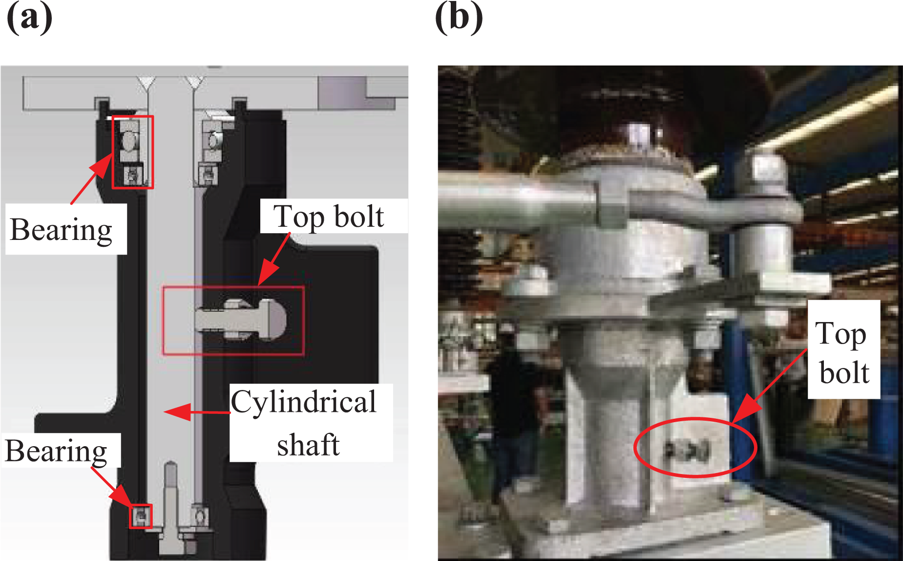
When the disconnector operates for a long time, mechanical faults and defects are easily caused by corrosion and contamination accumulation at various transmission parts. Typical mechanical defects are transmission jamming, inadequate opening and closing, and three-phase position asynchrony. Here, these defects of disconnector are simulated by setting defects on the disconnector as shown in Figure 1. The corresponding defect simulation schemes are as follows. Bearing jamming
The bearing seat for bearing and rotating post insulators can be designed as either a sealing structure or an unsealed structure by different manufacturers. After a long time of operation, the entry of dust, water vapor, and so on cannot be avoided regardless of the structure of the bearing seat, resulting in the loss and solidification of grease and the occurrence of bearing jamming defect. In the defect simulation, the threaded hole of
The defect simulation of bearing jamming. (a) Schematic diagram. (b) Physical model.
2. Operating shaft jamming
After long-term outdoor operation, the operating shaft may be jammed due to corrosion and accumulation of foreign matters between the hoop and the top rotating shaft. In the simulation experiment,

The defect simulation of operating shaft jamming. (a) Schematic diagram. (b) Physical model.
3. Three-phase position asynchrony
For the sake of saving cost, the disconnector for voltage less than or equal to 330 kV in China generally adopts three-phase mechanical linkage. Newly installed or overhauled disconnector needs to be debugged to meet the requirements of three-phase position synchronization. However, the debugging quality depends on the technician’s experience. The relative position of three-phase moving contacts and contact fingers will be different when the debugging is inappropriate, which will lead to the increase of contact resistance between the moving contacts and the contact fingers. In the defect simulation, the normal disconnector is manually operated until the three-phase moving contacts and contact fingers are about to contact. Then the length of the cross connecting rod of B phase is adjusted to make the contact between the contact fingers and the moving contact in advance, as shown in Figure 7.

The defect simulation of three-phase position asynchrony. (a) Contact in advance. (b) Normal phase.
Results and discussions
Normal state
The operating torque–rotation angle curves of twice closing operation of the disconnector under normal mechanical state are shown in Figure 8. It is obvious that the two curves coincide basically with the similarity of 0.9992, which indicates the good repeatability of the experiment.
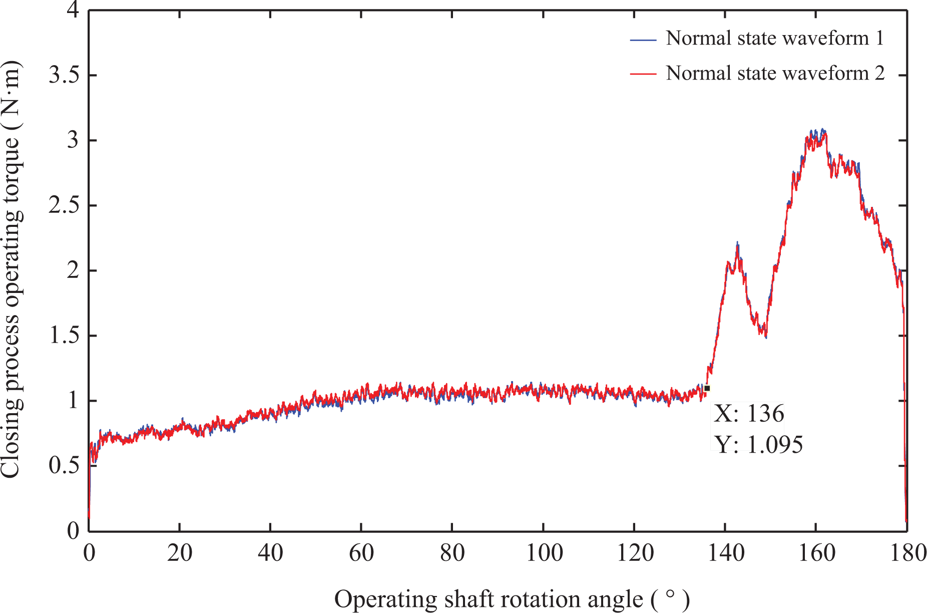
The closing operating torque–rotation angle curves in normal state.
Based on the action process of the disconnector, the detection curve in Figure 8 can be divided into two stages according to whether the moving contacts and the contact fingers are in contact. In the operating shaft rotation angle range of 0–136°, the moving contacts and the contact fingers are not in contact. In this stage, the detection device only needs to overcome the frictional resistance torque at the axle pins, bearings, and so on in the transmission mechanism. Correspondingly, the operating torque value is small and gentle. The average values of the two operating torques in this stage are 0.96 N·m and 0.97 N·m, respectively.
In the operating shaft rotation angle range of 136–180°, the moving contacts mesh with the contact fingers. Since the detection device needs to overcome the resistance torque generated by the contact forces (elastic force and friction) between the moving contacts and the contact fingers in this stage, the operating torque increases. The average operating torques measured twice in this stage are 2.26 N·m and 2.24 N·m, respectively, which are about 1.3 N·m larger than that in the noncontact stage. Due to the sequential contact of the moving contacts with the internal and external contact fingers, there are two typical peaks and a trough in the operating torque curve in this stage.
Some small fluctuations in the operating torque curves can also be observed from Figure 8, which are caused by the slight shaking of the disconnector and the detection device during the measuring process. As these fluctuations have little influence on the value and the trend of the operating torque, their effects can be ignored. The movement of the moving contacts and the contact fingers during the opening process is opposite to that during the closing process. Because the contact fingers store the elastic potential energy during the closing process and release the elastic potential energy in the opening process, the variation of the operating torque during the opening process is not as obvious as that in the closing process. Since the torque curve of the closing process changes significantly and can better reflect the movement process of the disconnector, the closing process curve is used in the subsequent analysis.
Bearing jamming
The operating torque and operating shaft rotation angle data are measured when the bearing is jammed. Figure 9(a) exhibits the operating torque curves of normal state and the bearing jamming state. The curve of operating torque additionally provided by the detection device is plotted in Figure 9(b).

The relevant operating torque–rotation angle curves in the condition of bearing jamming. (a) The contrast operating torque–rotation angle curves in conditions of bearing jamming and normal state. (b) The operating torque additionally provided in the condition of bearing jamming.
It is clearly in Figure 9(a) that the operating torque curve of the bearing jamming state is significantly different from the normal state. In the noncontact stage, the trend of the operating torque is obviously changed. Meanwhile, the value of the operating torque increases significantly, with an average of 0.71 N·m larger than that in the normal state. In the meshing stage, the trend of the operating torque is similar to that of the normal state. Both curves contain two typical peaks and one trough with almost the same locations of the peaks and the trough. The value of the operating torque in bearing jamming state is 0.48 N·m larger than that in the normal state on average.
Figure 9(b) suggests that the operating torque additionally provided by the detection device first increases gradually and then decreases. It is observed that the rotational speed of the rotating post insulator first increases and then decreases in the closing process of the disconnector, and that the angular velocity is large in the middle period of the process. Since the resistance value of the top bolt to the tightly coupled cylindrical shaft in the bearing base can be regarded as stable, the energy consumption rate of the resistance is proportional to the rotational speed of the post insulator, resulting in the operating torque additionally provided by the detection device first increases and then decreases in the closing process.
Operating shaft jamming
Figure 10(a) compares the operating torque curves between the operating shaft jamming state and the normal state. The operating torque additionally provided by the detection device when the operating shaft is jammed is plotted as a function of operating shaft rotation angle, as shown in Figure 10(b).

The relevant operating torque–rotation angle curves in the condition of operating shaft jamming. (a)The contrast operating torque–rotation angle curves in conditions of operating shaft jamming and normal state. (b) The operating torque additionally provided in the condition of operating shaft jamming.
Significant differences of the operating torque–rotation angle curves of the two states can be observed in Figure 10(a). Generally, the operating torque is significantly larger under the operating shaft jamming state than that in the normal state. In the noncontact stage, the operating torque increases sharply at the beginning, and then remains relatively stable. In the meshing stage, the variation of the operating torque is similar to that of normal state except the dramatic increase at the end of the closing. Since the operating shaft rotation speed is constant during the measurement, the operating torque additionally provided by the detection device should be theoretically the same everywhere when the resistance of the top bolt to the operating shaft is constant. However, the additional operating torque is not a constant, as shown in Figure 10(b).
It is observed that the relative position between the top rotating shaft (in Figure 6) of the operating shaft and the hoop is not relatively constant during the closing process of the disconnector. This is because there is a clear gap between the top rotating shaft and the hoop, which facilitates the installation. Therefore, under the reaction force of the driving arm during the closing process, the relative position between the hoop axis and the rotating axis of the top rotating shaft will change, leading to the unstable resistance of the top bolt to the operating shaft and the varied operating torque additionally provided by the detection device.
After the experiment, it is observed through the screw hole on the hoop that there is a concave shape (it is caused when penetrated the threaded holes on the hoop) on the top rotating shaft at the opening position, resulting in the virtual contact between the top bolt and the top rotating shaft at the beginning of the measurement. The top bolt presses the top rotating shaft when rotating over the concave shape, hindering the rotation of the operating shaft and causing the operating torque to increase sharply. It is also observed that there are scratches of different depth left on the top rotating shaft by the top bolt, which also indicates that the actual force between the top bolt and the top rotating shaft is not constant.
Based on the results shown in Figures 9 and 10, it can be concluded that the influence of the operating shaft jamming and the bearing jamming on the operating torque is different. It is related to the relative rotational speed and resistance of the jamming parts. When the operating shaft is jammed, the relative rotation speed between the operating shaft and the hoop remains unchanged, while the resistance applied by the top bolt changes somewhat during the closing process. When the bearing is jammed, the resistance provided by the top bolt remains basically the same while the rotation speed of the bearing first increases and then decreases. Therefore, at the beginning of the closing process, the operating torque additionally provided gradually increases when the bearing is jammed and rapidly increases when the operating shaft is jammed.
Three-phase position asynchrony
The operating torque curves of the three-phase position asynchrony state and normal state are shown in Figure 11(a). The operating torque additionally provided by the detection device in the defect of three-phase position asynchrony is shown in Figure 11(b).

The relevant operating torque–rotation angle curves in the condition of three-phase position asynchrony. (a) The contrast operating torque–rotation angle curves in conditions of three-phase position asynchrony and normal state. (b) The operating torque additionally provided in the condition of three-phase position asynchrony.
It can be seen from Figure 11 that the main difference of the operating torque curves between the three-phase position asynchrony and the normal state is in the meshing stage. Since the B-phase moving contact is in contact with the contact fingers in advance, the rotation angle of the operating shaft is advanced from 136° in the normal state to 133.9° in the three-phase position asynchrony when the moving contact is just brought into contact with the internal contact fingers. Due to the contact force between B-phase moving contact and internal contact fingers is larger than that between B-phase moving contact and external contact fingers, the resultant contact force between B-phase moving contact and contact fingers is larger than that of normal state, leading to the larger operating torque than that of normal state. The operating torque in meshing stage is 0.19 N·m larger than that of normal state on average. The maximum operating torque difference from the normal state is 1.17 N·m. In the noncontact stage, the mean value of torques under the two state is about 0.96 N·m, and the torque difference is almost zero.
Discussion
At present, the existing detection technology for the mechanical defect detection of disconnectors is still not perfect. The mechanical state of the disconnector cannot be effectively detected. The geometric mechanics deduction and experimental studies in this article demonstrate that the operating torque of disconnector will change with the mechanical state of the disconnector. It is verified that the change is measurable and quantifiable through the proposed detection method. Therefore, it is possible to detect mechanical defects based on operating torque.
According to the results demonstrated in this work, a practical diagnosis method for the mechanical defect of the disconnector is proposed, as shown in Figure 12. Comparing the measured operating torque–rotation angle curve with the normal state curve, when there is a difference in the total rotation angle, it indicates that there is an inadequate action or over action defect. Then the operating torque difference curve is obtained. According to whether the moving contacts and the contact fingers are in contact, the operating torque difference curve could be divided into two stages. If the operating torque difference is obviously greater than zero in the noncontact stage, it indicates that there is jamming defect. The type of jamming defect can be judged according to the trend of the torque difference curve at the beginning of the closing process, the operating torque additionally provided is gradually increased when the bearing is jammed and is rapidly increased when the operating shaft is jammed. If the operating torque difference fluctuates around zero in the noncontact stage, and the operating torque difference is obviously greater than zero in the meshing stage, it is implied that there is a defect of three-phase position asynchrony. It should be noted that the type of disconnector and the structure are various, resulting various mechanical defects. When this diagnosis method is used, the corresponding adjustment should be made according to the specific type of the disconnector.

The diagnosis process for the mechanical defect of disconnector.
Conclusion
In this work, an accurate operating torque detection technology is proposed, and a practical diagnosis method for mechanical defects of the disconnector is summarized, which can provide useful references for maintainers. The effect of mechanical defects on operating torque is explained by geometric mechanics. Based on this, a method of accurately detecting the operating torque of the disconnector off-line is proposed without destroying or changing the original shafting of the disconnector. Through the detection method, the operating torque curves of typical mechanical state are measured and compared, and a practical diagnosis method is summarized.
The proposed detection technique quantifies the mechanical characteristics parameters of the disconnector and provides a practical diagnosis method for mechanical defects of disconnector. But the diagnosis of the mechanical state of disconnector according to the measured operating torque curve is still artificial. The intelligent diagnosis has not yet been realized. Future work should be carried out on the intelligent diagnosis of mechanical state of disconnectors and on the online monitoring techniques to reduce the workload during maintenance.
Footnotes
Declaration of conflicting interests
The author(s) declared no potential conflicts of interest with respect to the research, authorship, and/or publication of this article.
Funding
The author(s) disclosed receipt of the following financial support for the research, authorship, and/or publication of this article: This work was supported in part by the Natural Science Foundation of Hubei Province (grant no. 2018CFB145).