
Abstract
This article proposes a cable-driven hybrid joint (CDHJ), focuses on the effects of external wrench payload and structural parameters on the wrench-feasible workspace for the preliminary design of the mechanism, and further discusses the wrench exertion capability of the mechanism under a certain configuration. This CDHJ has central rigid support with a revolute pair and a central compression spring support. Due to the unilateral property of cables and the flexible compression spring, the kinematic model cannot define the workspace directly; it should be combined with the statics for possible solution, including the spring lateral buckling model based on the elliptic integral solution. Moreover, a global tension index which is to evaluate the wrench-closure property of the global workspace, combined with an index which is to assess the size of the workspace, is proposed to better compare the effects of different external wrench payloads and different structural parameters on the workspace. Simulations were performed and demonstrated the correctness and feasibility of the inverse kinematics and workspace analysis of the joint. Hence, the proposed mechanism has potential use in robotics especially in wheelchair-mounted robotic manipulator joint.
Introduction
Since its birth in the United States and Japan in the early 90s,
1
the cable-driven mechanism (CDM) has been applied in various fields, due to the following remarkable characteristics: (1) The weight/load ratio of the mechanism is very high, especially suitable for hoisting operation
1
–3
; (2) end effector can achieve great speed and acceleration, especially for high-speed motion, like SkyCam with four cables and up to 44.8 km/h maximum speed
4,5
; (3) the workspace is very large, especially suitable for large-scale work occasions
5
; (4) the cable is flexible, highly force-sensitive, and safe, which is suitable for service robots,
4
such as rehabilitation institutions
6
–9
like cable-driven arm exoskeleton
6
; and (5) the cable is easy to disassemble and assemble, which is suitable for some occasions requiring rapid assembly
10
and reconfigurable systems
11,12
like cable-driven modules with passive joints.
12
However, the cables can only apply tensile forces, so cables remain in tension under any external load that need the presence of a large enough ballast force which is generated by a spring, gravity, and dynamic force.
13
From this point, the CDM configuration may be divided into three types as Figure 1, which is just a sketch of the CDM configuration model: CDM without central support like cable-suspended parallel mechanisms
13
–15
as shown in Figure 1(a) can provide very high load transmission capabilities and potentially very large workspace.
4,5
In this case, the base and the end effector are completely connected by the driving cables, and the degree of freedom and workspace are determined by the cables. This kind of CDM has more degrees of freedom, but its rotational workspace is relatively very small. CDM with central rigid support like cable-driven modules with passive joints as shown in Figure 1(b),
12,16
generally, has fewer degrees of freedom but higher stiffness, which increases the accuracy and stability among the workspace.
16
In this case, the base and the end effector are connected by rigid joints, which bring rigid constraints to the mechanism. The degree of freedom of the mechanism is determined by rigid joint, while the workspace is determined by cables. CDM with central compliant support like cable-driven flexible joint module,
17
cable-driven parallel robot with a spring spine
18
as shown in Figure 1(c), has complex deformation, which makes the model complex. In this case, the compliant support is used between the base and the end effector. Its degree of freedom and workspace are determined by the cables and the compliant support. The compliant support has the ability of continuous deformation, which not only restricts the end effector but also ensures that the mechanism has more degree of freedoms and larger workspace.

Configuration of CDM. (a) CDM without central support. (b) CDM with central rigid support. (c) CDM with central compliant support. CDM: cable-driven mechanism.
Much research has been done on the first CDM type as Figure 1(a), as the cable tension is difficult to actively adjust in this suspension-based manipulators, the stability and accuracy are becoming difficult to be controlled accurately among the workspace. 19 Yang et al. 20 and Chen et al. 21 developed an anthropopathic robotic arm. Each module adopts the second type as Figure 1(b). The rigid support is a three degrees of freedoms spherical pair, two degrees of freedoms universal joint, or one degree of freedom revolute pair. Gao et al. 18 probed deep into the humanoid neck mechanism, which is the third type as Figure 1(c). Combined with the latter two types, Ma et al. 16 Yigit and Boyraz 22 and Cafolla and Ceccarelli 23 –25 proposed the similar structure with our prototype. Ma et al. 16 proposed a class of two degrees of freedoms cable-driven parallel kinematics mechanism, which can be structured with low manufacturing and assembly difficulties. Yigit and Boyraz 22 proposed a very similar neck mechanism and analyzed the stiffness variation with the rotation of the joint based on Castigliano’s theorem. Cafolla and Ceccarelli 23,24 proposed a humanoid torso mechanism and carried out an experimental validation for each configuration while replicating human-like basic movements. 25
Moreover, workspace analysis is of great interest since the workspace geometry can be considered a fundamental issue for manipulator design, 26 robot placement in a working environment, and trajectory planning, 27 so this article aims to analyze the workspace of the mechanism. Due the cables can only work in tension, CDM workspace determination should meet this unilateral property. Several different types of CDM workspace have been identified and investigated, such as static equilibrium workspace, wrench-closure workspace, wrench-feasible workspace (WFW), 26 dynamic workspace, 19 and collision-free workspace (interference-free workspace). 28,29 Wrench-closure workspace is defined as the set of poses in which the manipulator can sustain any arbitrary external wrench when no upper bounds are placed on the cable tensions; however, WFW needs to set specified actuation limits of the cable. 26,28 –31 In addition, many applications require the end effector to exert certain force/moment combinations throughout the space. Accordingly, the most appropriate workspace to consider is the WFW, 31 which is able to interact with the physical real world and is the most practical workspace for the cable-driven robot systems. 29
Approaches for workspace determination can be classified as numerical or analytical. 28 Numerical methods are typically point-wise evaluation techniques, but the computational time will be significantly increased with increasing resolutions. Hay and Snyman 32 and Lim et al. 33 proposed an algorithm to a CDM as Figure 1(a) to analyze the workspace. Used the Dynamic-Q optimization algorithm, Hay and Snyman 32 looked into the optimal configurations of planar cable-driven parallel manipulators with a larger dexterous workspace. Compared with the numerical method, analytical formulations provide a more accurate description of workspace and insights into its geometry. Previous studies have been concerned with determining only the boundary of the workspace 28,31,34 for some particular manipulators with simple configurations. However, for a general CDM, this is almost impossible, especially when the tension bound is included. 30
Inspired by the latter two types of CDM as Figure 1(b) and (c), and combined the latter two characteristics, this article proposed a cable-driven hybrid joint (CDHJ) toward wheelchair-mounted robotic manipulator, which has central rigid support and a compression spring support. Wheelchair-mounted robotic manipulator is a typical type of the assistive robot. 35 It assists the disabled elderly people to accomplish activities of daily living, namely reaching, gripping, and picking up objects from a shelf or the floor, and so on. This article focuses on analyzing the WFW of the mechanism. CDHJ is a cable-driven, compression spring supported hybrid mechanism. To the best knowledge of the authors, there are only a few studies to analyze the lateral buckling of spring combined effect of bending and compression. Concerning the elastic stability under lateral bending and compression, the coil spring can be treated as an elastic beam. 18,36,37 Hence, we introduced the spring buckling model based on the elliptic integral solution 38 in our previous work. 39,40 In this article, we use the spring lateral buckling model 39,40 to carry out cable tension analysis. Then, the effects of external wrench payload and structural parameters on WFW are analyzed for the preliminary design of the CDHJ; the WFW determination is based on the numerical method. To evaluate the wrench-closure property of the global workspace, a global tension index 26,30 is proposed.
This article is organized as follows. The “Conceptual design” section presents the concept of CDHJ. Then, the kinematic and static modeling is presented in the “Inverse kinematics and tension analysis” section. Afterward, the WFW of the mechanism is investigated in the “Effects of external wrench payload and structural parameters on WFW” section. Finally, conclusions stemming from the results are presented in the last section.
Conceptual design
Various movements of the human upper limb are accomplished by multiple groups of skeletal muscle traction skeleton movement around the shoulder, wrist joint, and elbow joint. The key words of this musculoskeletal mechanism may be abstracted as cable-driven and variable stiffness. Based on this idea, the authors are working on the wheelchair-mounted robotic manipulator. The proposed mechanism driven by two cables as an elbow joint was designed for elbow joint module of the wheelchair-mounted robotic manipulator and includes a lower platform (base) and an upper platform (moving platform) as shown in Figure 2(a). The variable stiffness characteristics of CDHJ had been described in our previous work. 39 This article aims to analyze the WFW of the mechanism.

Diagram of CDHJ. (a) 3-D joint mechanism. (b) 2-D joint diagram. CDHJ: cable-driven hybrid joint.
From Figure 2(a), the two cables simulate biceps and triceps brachii of the human elbow joint, which was identified as a hinge joint to complete flexion and extension movements. Utilizing the advantages of a hybrid mechanism, the joint is designed as a series–parallel hybrid mechanism. The cables and the compression spring support the two platforms in concentric position and form the parallel part; the two rigid concentric shafts with a revolute pair form the series part. Shaft 2 is fixed to the lower platform; Shaft 1 passes through the upper platform and is supported by a linear bearing, restricting, and defining the bending motion of the compression spring. Therefore, the mechanism is called as CDHJ. The CDHJ has a total of two degrees of freedoms. One is used to perform flexion and extension movements of elbow joint and the other one is a translational motion, which is designed to adjust the stiffness of the spring to determine the joint system stiffness. 39
Inverse kinematics and tension analysis
The diagram of the CDHJ is illustrated in Figure 2(b). The upper and lower platforms were designed as thin homogeneous round plates, and centroids of mass are at points O 1 and O 2, respectively. Then, two Cartesian coordinate systems O 1 x 1 y 1 z 1 and O 2 x 2 y 2 z 2 were fixed to the centers of the lower and upper platforms, respectively. The global coordinate system is OXYZ, and the local coordinate system O 1 x 1 y 1 z 1 is consistent with OXYZ. The connecting point of cables 1 and 2 is denoted as A 1, B 1, A 2, and B 2, respectively; a denotes the distance from O 1 to A 1 and O 1 to A 2; b denotes the distance from O 2 to B 1 and O 2 to B 2; the distance from O 1 to the revolute pair center is denoted as d; l 1 denotes the cable length between A 1 to B 1; l 2 denotes the cable length between A 2 to B 2; and θ is the rotation angle of the upper platform around the Z-axis. The spring was simply drawn as an arc.
As mentioned before, the CDHJ has a total of two degrees of freedoms. The rotation is around the Z-axis, and the translational motion is on the X–Y plane. x and y denote the translational motions of the upper platform, which move along X- and Y-axes in the global coordinate frame, respectively. Under the rigid restraint effect of the middle rotation pair, the relationship of the translational motion relative to O 2 along the x 1-axis and that along the y 1-axis in the global coordinate system can be expressed as follows

Therefore, the generalized independent variable of the CDHJ can be defined as (y, θ) and the joint variable as (l
1, l
2). It is obvious that the (l
1, l
2) is the input and the translation and rotation of the upper platform (y, θ) is the output of the kinematics analysis. Denote

where
The driving cables only work in the tensioning state. Thus, all cables must be able to create tension forces to achieve the equilibrium of the upper platform. Figure 2(b) shows the static analysis model of point O
2 point on the upper platform. Due to the small mass of the upper platform, the gravity of the upper platform


where i = 1,2; Ti
is the size of cable tension;

where
Modeling of spring lateral buckling
To obtain cable tensions, static analysis of compression spring is needed. Timoshenko and Gere
36
pointed out that the coil spring under lateral buckling could be treated as an elastic beam, but it should consider the change in the length of the spring due to bending and compression since the change was not negligible as in the case of compressed beams. This concept of an equivalent beam of helical spring is in most engineering applications.
37
As shown in Figure 3, the equivalent beam statics analysis of compression spring is performed. The end wrenches of the spring satisfy

Force and moment balance system of the equivalent beam.
where
The following equations regarding F 1, F 2, and M can be derived 39,40


where
To really obtain the cable tension, some basic parameters of compression spring need to be determined. The spring is made of carbon steel. E is the elastic modulus, 196 Gpa; G is Young’s modulus, 78.5 Gpa; r is the radius of spring wire, 2.5 mm; D is pitch diameter of the spring, 40 mm; l0
is the initial length of the compression spring, 105 mm; n0
is the initial winding number of the compression spring, 8; and K is spring constant, 23,840 N/m. The spring bending stiffness is
Effects of external wrench payload and structural parameters (a, b, d) on WFW
Workspace definition
Many applications require the end effector to exert certain force/moment combinations (or wrenches) throughout the space. Accordingly, the most appropriate workspace to consider is the WFW, 31 which is able to interact with the physical real world and is the most practical workspace for the cable-driven parallel robot systems. 29 In this article, the WFW for CDHJ refers to the set of poses for which the system can be satisfied with positive cable tensions for a specified set of external wrenches within the specified actuation limits of the cable. 26,28 –33 This workspace is generated by the following conditions.
Wrench-feasible condition

Wrench-set condition
The cable mechanism is in the WFW where the end effector can perform an operational task which means that certain wrench requirements must be met. The certain wrench requirements may be called wrench exertion capability, 41 which is the payload capacity or capability to react to external disturbances (forces or moments), depends on the task that a robot has to achieve, or the various applications of the considered robot. 31,42 Besides this, CDHJ will be applied to the elbow joint of wheelchair-mounted robotic manipulator to help disabled elderly people with their activities of daily livings, 39,40 which were assessed by the International Classification of Functioning, Disability and Health (ICF) as a common coding system 43,44 which is a classification of the healthy components of functioning and disability and developed by the World Health Organization. Matsumoto et al. 44 monitored the activities of daily livings of an able-bodied participant for 5 days and identified 3964 activities based on the ICF. They found that lifting and putting down objects are the most frequent activities. Chung et al. 43 also pointed out that the majority of the ICF codes in the evaluation tasks from reviewed studies are picking up, reaching, putting down, or lifting in the mobility domain. Overall, assistive robotic manipulators like wheelchair-mounted robotic manipulator to help disabled elderly people with their activities of daily livings actually perform lifting and putting down objects mostly. So, in static equilibrium, according to the frame OXYZ in Figure 2(b), the set of all wrenches exerted on the moving platform of the CDHJ due to the end-effector payload, and the weight of link is of the form 45,46

where Gp
and Gk
are the gravity of the end-effector payload and the weight of the link, respectively;
External wrench conditions.

Cable-length condition
This condition avoids one-type workspace singularity. This type of singularity is sometimes referred to as an inverse kinematic singularity 47 ; actually, inverse kinematics has been used in the whole WFW analysis

Translational constraint condition
This condition shows structural size constraint, which can also be called another type workspace singularity. It is known from equation (1) that the translation motion along the X-axis is limited by (y, θ). Meanwhile, the structural size of CDHJ restricts the translation motion. Hence

The constant orientation WFW when θ is fixed is defined as follows

The total WFW can be thought of as the intersection of all constant orientation workspaces in the range [θ min, θ max], 30,32 is defined as follows

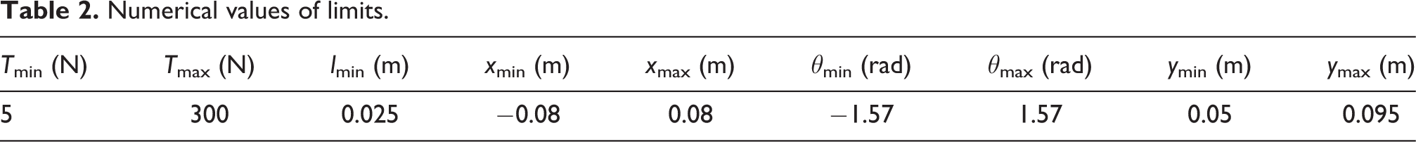
The values of the various maximum and minimum limits, in arbitrary units, corresponding to that required in inequations (9), (11), and (12), as used for all numerical examples, are given in Table 2.
Numerical values of limits.
Discretization method
A general numerical discretization workspace generation approach is employed here. Figure 4 shows the flow diagram of generating WFW. This method simply involves discretizing the WFW, which is the intersection of all constant orientation workspaces in the range [θ min, θ max]. According to Figure 4, the method steps are as follows:

Flow diagram of generating WFW. WFW: wrench-feasible workspace.
Determine motion parameters, including geometrical parameters (a, b, d), and spring parameters, the values of the various maximum and minimum limits, resolution m, n, and load case.
Discretize WFW by determining (n + 1) × (m + 1) points
Solve equations (1), (2), (5), (7), and (8) to obtain translation motion along the X-axis, cable length, and tension at each point
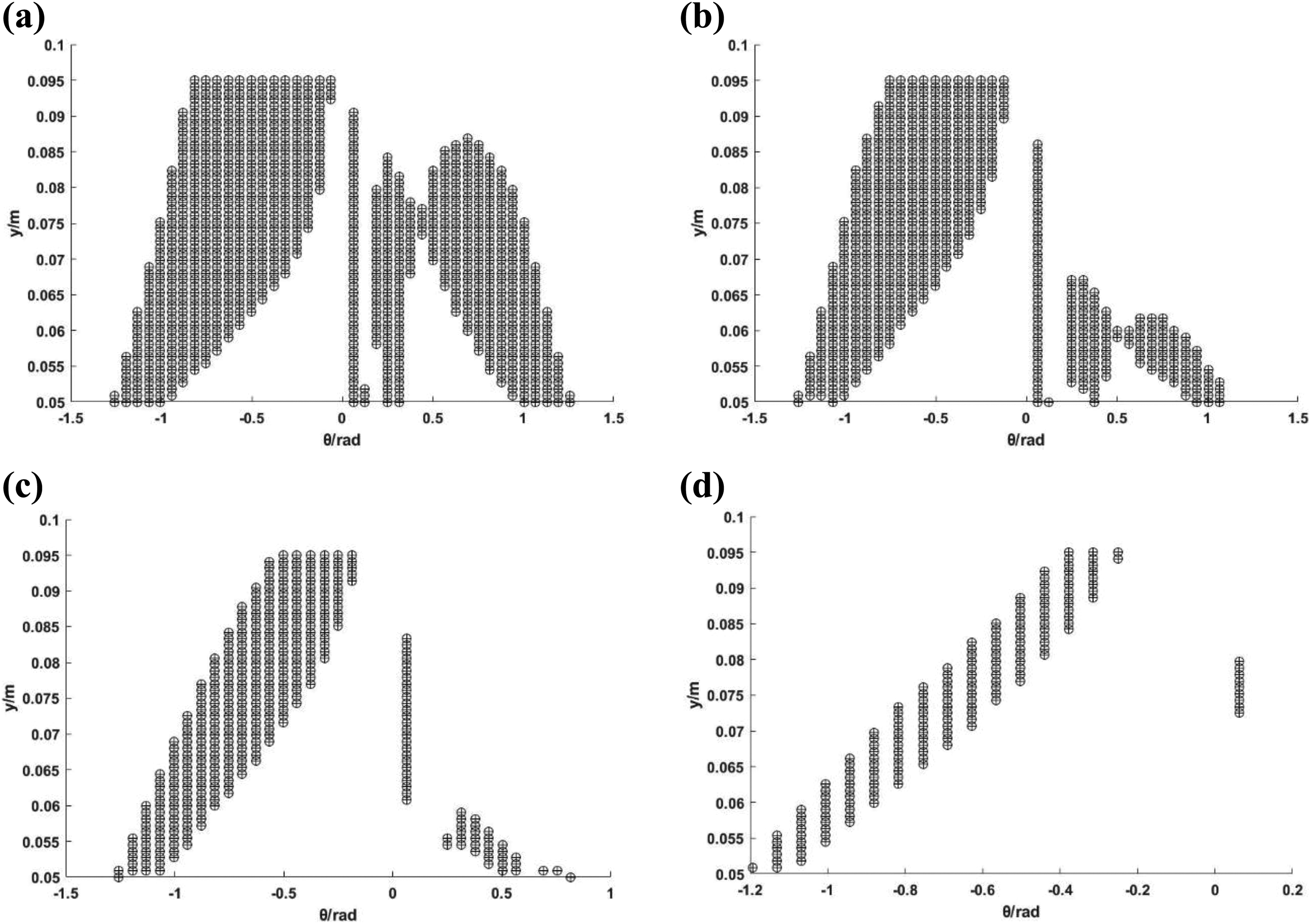
The possible motion ranges are first discretized into a number of points at a given resolution. Clearly, if a larger given resolution is used, it will increase accuracy but also increase computational time to search for all the points. In this article, the resolution is m = n = 50. This discretization method has been applied to workspace determination in the four-load case. The total WFW numerical example through Matlab is as Figure 5 for wrench case L1, L2, L3, and L4, when a = 0.05 m, b = 0.05 m, and d = 0.04 m. From Figure 5, the following features can be observed. First, it is evident that for this design, the WFW is highly dependent on both the load on the moving platform and the orientation of the platform; second, it is interesting to note that the presence of a singularity is at θ = 0°, for the cases at L2, L3, and L4, and only at L1 θ = 0° effectively divides the workspace into two symmetric regions; third, from Figure 5(a) to (d), with the human elbow extension/flexion range of motion of 110° 48 to perform activities of daily livings, the proposed mechanism satisfies requirements. This means the proposed CDHJ is suitable for the wheelchair-mounted robotic manipulator that assists the disabled elderly people in performing activities of daily livings.

WFW at a = 0.05 m, b = 0.05 m, and d = 0.04 m. (a) WFW at L1. (b) WFW at L2. (c) WFW at L3. (d) WFW at L4. WFW: wrench-feasible workspace.
To better analyze the variation of cable length and tension in the WFW, the simulation of inverse position and tension model through Matlab at a = 0.05 m, b = 0.05 m, d = 0.04 m, and L1 is shown in Figure 6. From Figure 6, the following features can be observed. First, the shape of cable lengths l 1 and l 2 and tensions T 1 and T 2 in the workspace is similar to Figure 5(a). This similarity verifies the correctness of the inverse kinematics and tension analysis from a certain point of view. Second, the change rule of cable lengths l 1 and l 2 has antagonistic characteristics. Namely, when the mechanism rotates clockwise as shown in Figure 2, θ is positive and cable length l 1 is larger; however, cable length l 2 is smaller. The contrary goes for counterclockwise rotation. Moreover, cable length l 1 and tension T 1 when θ is positive are, respectively, equal to cable length l 2 and tension T 2 when θ is negative; cable length l 1 and tension T 1 when θ is negative are, respectively, equal to cable length l 2 and tension T 2 when θ is positive. This shows the symmetry of mechanism motion, which is in accordance with intuition. This feature also verifies the correctness of the inverse kinematics and tension analysis from a certain point of view. Third, when θ is fixed, cable lengths l 1 and l 2 increase with the increase of y; however, tension T 1 and T 2 decreases with the increase of y. That is to say, when the rotation angle of CDHJ is constant, the larger the spring compression, the smaller the cable length and the larger the cable tension. It should be noted that when θ is zero, the compression spring for a linear spring meets Hooke’s law and cable tension T 1 is equal to T 2. Because the spring constant K selected in this article is large, the cable tension value does not meet the inequality (9) when the compression reaches a certain degree, which leads to that this position is no longer in the WFW. This can be changed by choosing a softer spring; when y is fixed and the mechanism rotates clockwise, cable length l 1 increases with the increase of θ; however, cable length l 2 decreases with the increase of θ. The contrary goes for counterclockwise rotation. This also reflects the antagonistic characteristics of the CDHJ cable length change rule. Besides, whether it is clockwise or counterclockwise, tension T 1 and T 2 decreases with the increase of θ.

Inverse position and tension model at a = 0.05 m, b = 0.05 m, d = 0.04 m, and L1. (a) Cable length l 1. (b) Cable tension T 1. (c) Cable length l 2. (d) Cable tension T 2.
Workspace quality evaluation
The proposed CDHJ will be used as an elbow joint module for the wheelchair-mounted robotic manipulator that assists the disabled elderly people in performing activities of daily livings. Determine whether activities of daily livings are possible and are elbow flexion and extension. Large elbow flexion and extension are needed for most activities of daily livings. 49 In other words, the larger the range of motion of the elbow is, the greater the ability of humanoid arm with shoulder and wrist to perform activities of daily living. Moreover, this article aims to discuss the effects of external wrench payload and structural parameters (a, b, d) on WFW. With this in mind, the problem addressed here is to analyze the effects, so that it yields the evaluation index of WFW, A (a, b, d). A (a, b, d) is the area of WFW for a given load on the upper platform, which is used to assess the size of WFW.
The traditional workspace quality indices developed for rigid-link parallel robots, like manipulability, dexterity, condition number, and stiffness, 26 which mostly depend on the conditioning of the Jacobian matrix, 50 are inadequate for CDMs and cannot be employed straightforwardly, 30,41 because they did not consider cable tension distribution situations. 51 For CDMs, a tension factor (TF) is proposed to be used as a performance index to evaluate the quality of WFW at a specific configuration. 26,30,41,47 TF is defined as follows

where

Cable tension and TF at θ = −58°at a = 0.05 m, b = 0.05 m, and d = 0.04 m. (a) Cable tension and TF at L1. (b) Cable tension and TF at L2. (c) Cable tension and TF at L3. (d) Cable tension and TF at L4. TF: tension factor.
The TF is a local measure because it characterizes the tension distribution at a given posture of the moving platform. 26,30 Figure 8 shows TF approaching (y, θ) limit for the four-load conditions in the WFW. From Figure 8, the shape of TF at four-load case is similar to Figure 5. In Figure 8(a), θ is close to 0°, TF tends to 1, because when θ is 0, the compression spring for a linear spring meets Hooke’s law and cable tension T 1 is equal to T 2. And when y is fixed, the larger the rotation angle, the smaller the TF. This change rule is also shown in Figure 8(b) to (d). But in Figure 8(b) and (d) namely, at L2 and L4, when θ is fixed, the larger the y, the smaller the TF. This means that the greater the compression of the spring, the better the wrench-closure of the mechanism.

TF at a = 0.05 m, b = 0.05 m, and d = 0.04 m in the WFW. (a) TF at L1. (b) TF at L2. (c) TF at L3. (d) TF at L4. TF: tension factor.
TF is just a local measure, so a global tension index, G (a, b, d), is proposed to evaluate the wrench-closure property of the whole WFW in every configuration. Due to G (a, b, d) can be computed numerically for the finite workspace, it is defined as follows 26,30

Similar, a larger G (a, b, d) is more favorable. G (a, b, d) is different in different structural parameters (a, b, d). For such cases, the G (a, b, d) can be adapted to evaluate the workspace quality in every configuration. The configuration that results in the best G (a, b, d) will be considered as the optimal solution.
In summary, the evaluation indexes for WFW quality are A (a, b, d) and G (a, b, d). A (a, b, d) is to assess the size of WFW and G (a, b, d) is to evaluate the wrench-closure property of the global workspace. Table 3 presents the values of these two indexes at a = 0.05 m, b = 0.05 m, d = 0.04 m, and four-load cases. The mechanism at different load has different WFW, and when the mechanism is not loaded, the workspace is the largest. Contrast the results of each G (a, b, d), it should be noted that this configuration at a = 0.05 m, b = 0.05 m, and d = 0.04 m under the load cases L2 and L4 has poor wrench-closure property, which wrench-closure singularities may be occur. It needs to optimize structural parameters for better wrench-closure property to bear the wrench cases as L2 and L4.
A (a, b, d) and G (a, b, d) at a = 0.05 m, b = 0.05 m, and d = 0.04 m and four-load cases.

Structural parameters (a, b, d) effects on WFW
WFW is highly dependent on the manipulator design, the load on the end effector, and the end-effector orientation. So this section aims to analyze structural parameters (a, b, d) effects on WFW at different load cases for CDHJ preliminary design. The two evaluation indexes of WFW mentioned in the previous section, A (a, b, d) and G (a, b, d), are used to evaluate workspace in different configurations for a given load on the upper platform. Hence, two different measures can be defined as follows:

subject to 0.035 m ≤ a ≤ 0.08 m, 0.035m ≤ b ≤0.08 m, and 0.025m ≤ d ≤0.055 m other parameters such as Tables 1 and 2. Due to the length of the article, this section only analyzes structural parameters effects on the WFW under L1 and L2.
Discretize a × b × d into w × w × w points. Traverse w × w points of (a, b) to figure out the corresponding A (a, b, d) and G (a, b, d) for d (w points) as shown in Figure 9. Each value in Figure 9 is calculated like this. When a and b take a value and then traverse d (w points) to calculate A (a, b, d) and G (a, b, d) corresponding to the conditions such as inequation (9), (11), and (12). Numerical analysis was implemented with Matlab at w = 5. Figure 9 shows A (a, b, d) and G (a, b, d) at traversing a × b × d at L1 and L2. There should be 25 curves in Figure 9(a) to (d). The maximum target value falls on curves 1, 2, 4, and 6. The negative value of curve 3 is caused by the fitting error like curve 5. As seen from Figure 9(a) and (b), under load case L1, when d = 0.025 m, a = 0.035 m, and b = 0.035 m, A (a, b, d) is the maximum, but when d = 0.055 m, a = 0.035, and b = 0.035 m, G (a, b, d) is the maximum. Similarly, at L2 from Figure 9(a) and (b), A (a, b, d) is the maximum at d = 0.028 m, a = 0.035, and b = 0.0688 m; G (a, b, d) is the maximum at d = 0.0448 m, a = 0.0575, and b = 0.035 m. This means that when (a, b, d) gets the maximal value of A (a, b, d), G (a, b, d) is not the maximal value. That is to say, when the WFW is relatively large; however, the wrench-closure property is not necessarily relatively good; when the wrench-closure property is relatively good, however, the WFW is not necessarily relatively large. In other words, CDHJ optimal design should be multiobjective optimization, taking A (a, b, d) and G (a, b, d) into account in the future as well as the stability of CDHJ like stiffness characteristics.

A (a, b, d) and G (a, b, d) at traversing a × b × d. (a) A (a, b, d) at L1. (b) G (a, b, d) at L1. (c) A (a, b, d) at L2. (d) G (a, b, d) at L2.
Discussions
Figure 5 shows the effects of external wrench payload on the WFW in a given configuration. This also simply shows the wrench exertion capability 41,45 of CDHJ. Figure 9 shows the effects of structural parameters (a, b, d) on the WFW in a given load case. It shows that a compromise is needed in the preliminary optimization design of the mechanism, because the area of workspace A (a, b, d) is relatively large; however, the global tension index G (a, b, d) is not necessarily relatively large. Furthermore, the CDHJ is a variable stiffness mechanism which is analyzed in previous work. 39 So the preliminary optimization design needs considering the stiffness characteristics.
In this section, the wrench exertion capability of the mechanism under a certain configuration is further analyzed. In this article, the CDHJ is proposed for the wheelchair-mounted robotic manipulator, so the external wrench payload case is as the form of L4. By using the analysis method in the previous section, it can be concluded that the WFW of the mechanism at L4 is the largest at a = 0.035 m, b = 0.0688 m, and d = 0.025 m. In this configuration, the load cases and the values of A (a, b, d) and G (a, b, d) are presented in Table 4. Figure 10 shows the WFW at L4–L7. Comparing Table 3 with Table 4, it can be concluded that at a = 0.035 m, b = 0.0688 m, d = 0.025 m, and L4, the WFW is relatively large and the wrench-closure property is relatively good. From Table 4, as the load increases, the workspace becomes smaller as shown in Figure 10. And when the gravity of the end-effector payload and the weight of a link is 50 N, the WFW is very small and almost 0; this almost achieves the maximum wrench exertion capability of the mechanism. Moreover, as the load increases, G (a, b, d) becomes smaller, and the wrench-closure property becomes worse.
WFW at a = 0.035 m, b = 0.0688 m, and d = 0.025 m. (a) WFW at L4. (b) WFW at L5. (c) WFW at L6. (d) WFW at L7. WFW: wrench-feasible workspace.
External wrench and A (a, b, d) and G (a, b, d) at a = 0.035 m, b = 0.0688 m, and d = 0.025 m.

Conclusions
This article puts forward the CDHJ for the wheelchair-mounted robotic manipulator and aims to discuss the effects of external wrench payload and structural parameters (a, b, d) on WFW for the preliminary design of the mechanism. To better compare the effects of different external wrench payloads and different structural parameters on WFW, the WFW quality evaluation indexes A (a, b, d) and G (a, b, d) are proposed. A (a, b, d) is to assess the size of WFW, and G (a, b, d) is to evaluate the wrench-closure property of the global workspace. All the WFW are obtained by discretization method based on inverse kinematics and tension analysis with modeling of spring lateral buckling. With large workspace, smooth motion, 22,39 and light structure, the proposed CDHJ might have potential use for the wheelchair-mounted robotic manipulator, which will be verified by experiments in the future research, including the shoulder and wrist joint module.
Footnotes
Declaration of conflicting interests
The author(s) declared no potential conflicts of interest with respect to the research, authorship, and/or publication of this article.
Funding
The author(s) disclosed receipt of the following financial support for the research, authorship, and/or publication of this article: This work was supported by the National Natural Science Foundation (NSF) of China (51275152 and 51875167) and NSF of Hebei Province (2018202114).