
Abstract
Intelligent manufacturing as the development direction of the new generation manufacturing system has become a hot research topic. Computer numerical control (CNC) machine tools are the core manufacturing equipment in discrete manufacturing enterprises, collecting and monitoring the data is an important part of intelligent manufacturing workshops. It has a great significance to improve the production efficiency of enterprises and eliminate information islands. The purpose of this article is to solve the problems of data acquisition and monitoring of CNC machine tools in the manufacturing workshop of enterprises. This article uses FOCAS data acquisition method to research and develop the data acquisition and monitoring system of CNC machine tools in intelligent manufacturing workshop. The research results show that the equipment information model based on MTConnect protocol and FOCAS can solve the data acquisition and storage functions of CNC machine tools well. Using the object-oriented Petri net model, it can solve various uncertain factors in numerical control (NC) machining tasks and realize the monitoring function of CNC machining tasks in the workshop. Based on the NC program analysis, the calculation method of machining time in the NC program can determine the preventive maintenance cycle of the machine based on the machine fault information. Based on VS2013 development environment, Qt application framework and SQL Server 2012 database, the numerical control machine tool data acquisition and monitoring prototype system was developed, and the system was verified in the workshop to prove the effectiveness of the system.
Introduction
As the pillar industry of China’s national economy, manufacturing is the basis for enhancing national competitiveness and raising the national economy. It has always been highly valued by the state. With the development of science and technology and the drastic changes in the industrial environment, the pattern of the world’s manufacturing industry is undergoing tremendous changes. How to seize this development opportunity to realize the transformation of China’s manufacturing industry from large to strong has become an important issue facing China’s manufacturing industry. With advances in wireless sensor networks, big data, mobile and cloud computing, networked physical systems can better integrate cyberspace with the physical world than ever before. In addition, cloud-based systems can provide massive storage resources and low-cost computing, as well as the flexibility to customize operating environments for complex industrial applications. 1 Compared with traditional information systems, the available computing power is increasingly entering the technical system. This is a common observation. Therefore, information and communication technology not only automates the management process but also the technical process in the physical world. More and more automated. The traditional CNC machining monitoring system has limited data characteristics, low adaptability, and low transmission efficiency, making it difficult to implement intelligent online evaluation. 2
With the changes in the global economic structure and the development of manufacturing technologies, networked physical systems integrated intelligent manufacturing systems have become a general solution for upgrading manufacturing in developed and developing countries. 3 The intelligent manufacturing workshop combines with information technology, network technology, manufacturing technology, automation technology, modern management technology, and system engineering technology. It integrates real-time data of physical workshop and workshop information system to realize people, machines, objects, and environment in the workshop. The integration of the entire process in the network environment eliminates the silos of enterprise information and has various functions such as intelligent production scheduling, intelligent device monitoring, intelligent fault diagnosis, intelligent energy management, and so on, ultimately improving the production efficiency of the workshop and improving product quality. Reduce the cost of production. In manufacturing, energy efficiency is a challenging task due to the complexity of manufacturing systems and the flexible operation of highly customized products. To this end, it is necessary to estimate the energy consumption of the processing task and thus estimate the processing cost. 4,5 The intelligent manufacturing workshop is based on the data interconnection between the physical workshop and the information workshop. Through the information technology system and the key technologies of the industrial Internet, it can optimize the analysis of various information in the workshop, through online monitoring of the working conditions, data integration and management, and intelligent simulation analysis. 6 Technologies such as intelligent management decision-making continue to improve the performance of the workshop equipment and the efficiency of the workshop management, so that the workshop manufacturing process is finally intelligent. It has the characteristics of intelligent equipment interconnection, high real-time data, integrated production management, manufacturing network synergy, and real-time data analysis and feedback. 7 The production characteristics of a wide variety of products but a small number of job shop industries result in a dynamic load sharing process for each machine. Its dynamic conditional operation directly affects the reliability of machine tool components. 8 Guangda et al. studied the application of the tool breakage monitoring system to detect tool breakage in an unattended automated workshop. 9 In order to effectively and accurately identify tool breakage, the spindle power data are preprocessed based on the mapping between spindle power and block number, one of which affects tool breakage by empirical mode decomposition isolation. 10
Ghimire et al. pointed out that the main challenge facing manufacturing companies today is the increasing complexity of their processes, which affects the entire decision-making process. Therefore, integrating evolving technologies in the Internet of Things (internet of things) domain into applications for project management is a very important area of research. By reducing the decision-making time based on the internet of things technology, providing a framework for efficient project management, achieving goal by dynamically building situational awareness based on existing manufacturing processes, by implementing an effective project management platform in the construction industry, and proposed framework was validated in a practical industrial scenario. 11 In order to achieve the goal of intelligent manufacturing, Liu and Jiang proposed the network physical system (CPS) architecture of the workshop. The proposed architecture provides guidance for building CPS systems from hardware interconnection to data acquisition, processing and visualization, and ultimately knowledge acquisition and learning. 12 Lee et al. propose a comprehensive dynamic model that takes into account all interactions between the machine structure, the control system, and the cutting process. Modal truncation techniques using steady-state dynamic analysis over selected locations of interest and frequency are applied to improve the efficiency of mechatronic simulation, including the cutting process. 13 Duro et al. propose a novel multisensor data fusion framework to identify the best sensor locations for monitoring cutting operations, to identify sensors that provide the best signals, and to derive signals with enhanced periodic components. The experimental results show that by using the framework, only three sensors are used, the signal interpretation is significantly improved, the reliability of the monitoring system is enhanced, and it is applicable to various processing parameters. The framework provides the main limitations for overcoming arcGIS engine (AE)-based monitoring. 14 Edrington et al. believe that modern manufacturing plants contain a variety of different types of processing equipment, each supporting different proprietary interfaces and communication protocols. This diversity makes it challenging for store managers to monitor and maintain their machines. But the emerging MTConnect standard enables monitoring systems to accurately and consistently collect data from any MTConnect-compatible machine, regardless of brand or source. 15 Oliveira and Álvares believe that the new era of manufacturing, Industry 4.0, will require a large use of mechatronic products. In this case, there are network physical systems and the Internet of Things. These are represented by platforms that are integrated through a connection protocol that allows for extensive sharing of information between different devices. The design of these applications requires a way to set requirements by reducing the complexity inherent in the development of these systems. 16 Wu et al. propose a reasonable fixture and adaptive CNC machining technology to provide a systematic solution for the processing of near net shape blade roots, tip and leading edge and trailing edge (LTE). 17 Wang et al. designed a remote monitoring system for air jet loom workshop based on B/S structure. Remote monitoring in the workshop can improve production efficiency and help production management. 18 Saez et al. present a framework for evaluating the performance of manufacturing systems in real time using hybrid simulation. It monitors the continuous and discrete variables of different machines to analyze performance using a virtual environment that runs synchronously with plant floor equipment as a reference. 19 However, in the research field of product service systems and related computerized maintenance systems, there is a lack of research on how to integrate knowledge from different stakeholders into the maintenance and service planning process, which is important for modern digital manufacturing systems to reduce machines. 20 Gwanghee and Joonryong proposed an intelligent data acquisition system based on data compression technology for structural health monitoring of civil structures and its effectiveness using random signals (El-Centro seismic waveforms). 21 Jianhui et al. believed that the different requirements of assembly, workshop monitoring is a three-tiered approach, including data acquisition, data processing and data matching, to establish intelligent monitoring kanban, and establish a monitoring model in the on-site assembly process. 22 Dos Santos et al. proposed a micromechanical performance evaluation by monitoring and predicting the positioning error in a circular trajectory. The data monitored by the trellis encoder is used to draft a method for implementing an experimental plan for monitoring and predicting positioning errors. 23 Panda et al. have developed and implemented an Integrated Data Acquisition (DAQ) device system based on Monitoring and Data Acquisition (SCADA)/Human Machine Interface (HMI) for remote control and monitoring of fido technology standard (FTS). 24 Downey et al. introduced a multisensor automatic data acquisition system with various sensors that measure acoustic emissions, cutting forces and vibrations mounted on the machine turret, and an automatic image acquisition system that can be used at each operation. Post-real-time monitoring of tool wear. 25
Drake et al. introduced some machine condition monitoring signals recorded by the data acquisition system, emphasizing the causal relationship between machine components and signal characteristics, and demonstrating the applicability of vibration signal kurtosis as a measure of the spindle bearing state. 26 Zhang designed and developed a multimedia sensor network intelligent warehouse monitoring system based on multisensor set, distributed processing, and event trigger monitoring. This can better provide warehouse environment parameter monitoring, event triggering, or continuous remote monitoring. 27,28 The safe and reliable operation of TWR requires a data acquisition and control system. Patel et al. introduced the detailed design and comprehensive test results of the data acquisition and control system of the TWR test bed. 29 Nathanael et al. introduced the development of monitoring system development to obtain real-time information on the use of each CNC machine component through component grouping according to its operating phase. For example, power-on state, machine ready state, or spindle running state. 30 Based on the actual situation of the current enterprise and the abovementioned research status at home and abroad, it can be found that: (1) At present, the degree of digitization in the production process is low, and the manual monitoring of the CNC machine tools for core equipment in the workshop is generally used, and more data storage is only produced in the production process. Staying in the artificial paper storage stage, the timeliness and correctness of the data are not guaranteed. At the same time, the “information island” in the workshop is widespread. The production planners and equipment managers cannot manage the real-time status of the machine tool. The actual production efficiency of the equipment is counted, and the utilization status of the workshop equipment cannot be known in time to make corresponding decisions. (2) Although the intelligent manufacturing workshop has received extensive attention recently, it is still in the stage of conceptual development and theoretical research. It has not yet formed a mature landing application theory and method. It is actually put into production and application less, and still needs to further develop its key technologies and applications. the study. (3) Although CNC machine tools are more and more open, due to the large number of manufacturers, their communication interfaces and data standards are different. Uniform data collection for multisource heterogeneous devices is difficult, lacks versatility, and lacks unified data. Collection standards, which do not meet the requirements of intelligent manufacturing workshops for high integration of device data. (4) The degree of refinement of production monitoring by enterprises is insufficient. At present, the monitoring of machine tools is mostly concentrated in state monitoring. For the time prediction and tracking monitoring of machine tool processing tasks, the traditional counting method can not meet single-piece small batches. The requirements of the production model cannot provide data support for production dynamic management.
In this article, the device data communication protocol MTConnect is researched firstly, and the machine tool information model is constructed. The machine tool data acquisition and storage is realized based on MTConnect and FOCAS. The shop NC machining task model is established, and the time calculation method of each link in the task model is proposed. Based on the analysis of NC program, the calculation method of machining step time is proposed. According to the machine fault information, the calculation method of preventive maintenance cycle of machine tool is proposed, and the forecasting time of task processing is completed. The processing progress of CNC machining task based on real-time information driven by workshop is studied. Monitoring method; developed a numerical control machine tool data acquisition and monitoring prototype system, realizing the remote real-time data acquisition and CNC machining task monitoring of CNC machine tools in the workshop.
Proposed method
CNC machine tool data acquisition method
To achieve data acquisition for machine tools, you first need to determine the data acquisition method of the machine tool. At present, the data acquisition methods of CNC machine tools can be divided into programmable logic controller (PLC) acquisition, macroprogram output acquisition, external sensor acquisition, and open CNC system interface acquisition. As shown in Table 1, for the analysis of these kinds of machine data collection methods, each method specialty.
Machine data collection method features.

According to the above analysis, it can be seen that the interface of the open CNC system does not require additional hardware equipment and has the advantages of being able to collect various types of machine tool information in real time, low real-time technical difficulty, and low implementation cost. The CNC machine tools in the target enterprise workshop adopt FANUC numerical control system and have Ethernet port. Therefore, according to the actual situation of the workshop and data collection requirements, the system uses the CNC information base and communication development interface of FANUC numerical control system provided by FANUC to communicate with the machine tool. Complete data collection.
In the MTConnect protocol, the adapter is responsible for direct communication with the CNC machine, and the data are collected and sent to the agent. This article is mainly for FANUC system CNC machine tools. FANUC CNC system provides FOCAS development kit for users to collect machine data. Therefore, this article uses FOCAS development kit to realize data acquisition of adapter to machine tool. FOCAS is a CNC information base and communication software package provided by FANUC for users. It can connect PC and CNC system through Ethernet (TCP/IP) or HSSB (High Speed Serial Bus) to exchange various data and information to realize machine tools. Real-time data collection. FOCAS encapsulates the underlying communication protocol of the CNC, allowing users to use C++ to call the interface, complete the information exchange with the CNC system, and use FOCAS for CNC information collection.
FOCAS provides 18 types of function functions such as CNC control axis, NC program related, tool management, and alarm information. These function functions enable real-time acquisition of machine data. Therefore, according to the MTConnect standard, this article establishes the information model of CNC machine tool equipment in the target workshop for the data acquisition requirements of CNC machine tools in the workshop and the components of the machine tool. The equipment information model of CNC machine tools mainly includes three components: axis, controller, and system: The subsystem of the shaft consists of a spindle and three feed axes X, Y, and Z. The subpart of the controller is processing path information, and the subsystem of the system is electrical system information.
System network connection method
The system network is mainly divided into three layers: equipment layer, workshop layer, and system layer. The CNC machine tools in the system target workshop all have Ethernet ports. Therefore, the machine tool networking method uses network connection based on industrial Ethernet and TCP/IP technology. The network structure in the workshop adopts a ring-and-star combination topology in each area. Configure a network switch. The switches are connected by optical fibers and form a ring network. The star structure is adopted inside the area, and the CNC machine tool and the on-site industrial computer are connected to the corresponding regional switch through the Ethernet port. The system server and the management machine control all machine tools through the industrial Ethernet connection, real-time status monitoring of each CNC machine tool, and acquisition, storage, and statistical analysis of the process data. The workshop network needs to be integrated with the enterprise LAN. Considering the communication security problem, the workshop network is isolated from the enterprise LAN through the hardware firewall, which can improve the network security of the workshop to a certain extent. Through this networking method, the machine tool of the workshop can be integrated with the entire enterprise network, and the remote online monitoring of the CNC machine tools in the workshop can be directly realized, which can meet the requirements of enterprise informatization, and at the same time, the network of the whole system is isolated by the workshop network and the enterprise network through the firewall. The connection is shown in Figure 1.

System network connection.
One of the most fundamental problems facing intelligent manufacturing workshops today is the data collection and integration of many devices in the physical workshop. Automated equipment has become more and more popular in manufacturing. These equipments generate a large amount of data anytime and anywhere in the production process. It is especially important to collect the data of equipment manufacturing in order to realize the information interconnection of various elements in the workshop. MTConnect is a versatile, workshop-level device communication standard that has been widely adopted by FANUC, Siemens, Mazak, and many other device manufacturers over the years. For many data interfaces in the workshop, MTConnect provides a common method and communication method for plant equipment, assets, and data. It is not a new technology, but an open system based on the widely used definition of HTTP and XML Internet technologies. Sex standard. MTConnect’s open, extensible, and open source free features make MTConnect very compliant with the “plug and play” requirements for device data collection in intelligent manufacturing plants.
According to the MTConnect standard, this article uses the XML language to describe a type of device information in the shop floor. XML is a common text data format, which can clearly describe the device’s composition, accurately define the data types and monitoring methods monitored by the device, and its format is highly scalable, which is convenient for users to customize and expand, suitable for network integration. The manufacturing features are easy to integrate with the upper system.
System architecture
The overall architecture of the CNC machine data acquisition and monitoring system can be divided into: hardware layer, data layer, technology layer, functional layer, and user interface layer, including: Hardware layer: The hardware layer is the most basic physical hardware support for the system operation, including the CNC machine tools in the workshop and the network equipment such as Ethernet. The CNC machine tool is connected to the workshop Ethernet through the Ethernet port to realize the CNC. Data transfer between machine tools and systems. Data layer: The data layer is the data foundation of the whole system implementation, covering data acquisition communication and data storage. The system adopts the MTConnect protocol for machine tool data acquisition and communication and realizes the data acquisition of the machine tool through the data acquisition open interface of the numerical control system. The data storage includes the storage and management of the real-time running data, fault data, and processing task data of the whole system. Technology layer: The technical layer is the technical basis for the realization of the whole system. The key technologies involved in the system include machine tool data acquisition technology, data communication technology, database technology, processing task modeling technology, numerical control program analysis algorithm, task processing time prediction. Algorithm, preventive maintenance cycle algorithm, processing progress monitoring technology. Function layer: The function layer is mainly responsible for the realization of the main functions of the system, including the machine status monitoring function, the processing progress calculation function, and the efficiency failure analysis function. The machine status monitoring function is responsible for real-time online monitoring of machine tool machining status, spindle data, program information, parameter settings, and alarm information; the machining task monitoring function is responsible for monitoring the current status, completion status and remaining time of the shop’s CNC machining tasks. And the fault analysis function is responsible for statistical analysis of the machining time and fault information history of the machine tool, calculating the machining efficiency of the machine tool and generating relevant statistical charts. Application layer: The application layer is mainly responsible for providing a human–computer interaction interface, providing an intuitive graphical display for each function of the system and responding to the user’s operation.
The functional modules of the system include a user login management module, a data acquisition module, a database management module, a processing progress monitoring module, and a processing efficiency calculation module. The user login management module is mainly responsible for managing user login and user information, verifying the user’s username and password, realizing user login, assigning different permissions to different users, and supporting new deletion of user information. The data acquisition monitoring module is mainly to realize the data acquisition communication and monitoring display of the machine tool, establish the equipment information model according to the MTConnect machine tool communication standard, realize the data acquisition of the machine tool through the FOCAS interface, and complete the data communication between the system client and the machine tool according to the data communication protocol. The data are stored in the database system for unified management, and the data display in the user interface enables real-time monitoring.
The processing efficiency calculation module mainly realizes the machine tool processing time according to the machine tool history processing record, calculates the efficiency information of each machine tool’s operation rate, utilization rate and overall equipment effectiveness (OEE) by counting the processing time, and graphically calculates the efficiency of each machine tool in the workshop. The fault information statistics module mainly counts the machine tool failure time according to the machine fault information history record, and simultaneously collects information such as the fault type distribution and duration of each machine tool, and generates a statistical chart to visually display the machine fault condition. The processing task monitoring module mainly completes the monitoring of the NC machining tasks in the workshop. Through the modeling of the machining tasks and the analysis of the time of each task, the processing time of the task model and each element in the task is obtained, and the time required for the machining task is estimated. And tracking the processing tasks being executed to calculate the current task completion rate and remaining processing time.
Experiments
Object-oriented NC machining task Petri net model
Although the classical Petri net can effectively describe the system structure and deal with the system relationship, its model structure is complex. When the number of nodes in the system increases, its complexity will increase sharply. It is difficult to model complex systems, and the classic Petri net model has closed, no clear system input and output, cannot effectively decompose and integrate the system. Therefore, based on the classical Petri net, combined with the object-oriented thinking, an object-oriented Petri net is derived. The use of object-oriented Petri net model to represent CNC machining tasks has the following advantages: (1) ability to display task objects and object relationships, (2) object-oriented, intuitive image, and (3) modular model, clear hierarchy.
There are many equipment resources involved in the NC machining tasks in the workshop, the process flow is complex, the content of different tasks is different, and the dynamics are strong. It is difficult to analyze the entire task flow directly. Therefore, according to its characteristics, one can complete one. The NC machining tasks are divided into three levels: task layer, process layer and step layer: Task layer: A CNC machining task is divided into several process executions according to the different resources realized in each part of the task. Therefore, this article defines the process as CNC machining, auxiliary and equipment for the same workpiece on the same equipment. Maintenance, measurement and other tasks are collectively referred to as a process in a task, so a CNC machining task can be represented as a sequence of several processes to complete; Process layer: In one process, it is necessary to perform a number of work steps according to the actual process arrangement. According to different process actions, this article divides the work steps in the numerical control machining process into auxiliary work steps, processing steps and measurement steps. Step layer: In order to improve the degree of fineness of processing task monitoring, the modeling of NC machining tasks in this article goes deep into the step layer, and the execution flow of different types of steps is different. The auxiliary steps include general assistance. Action and preventive maintenance actions, first determine whether it is necessary to perform preventive maintenance of the machine tool, if necessary, perform maintenance and then perform auxiliary action, otherwise directly perform auxiliary action.
NC program processing time algorithm
The NC program processing time calculation in this article is realized by the analysis of the NC program. The NC program is a direct implementation of the NC machining process. Therefore, the processing time algorithm for the NC program analysis is more accurate than the case-based reasoning and neural network method estimation and can cope with the changes of the product structure process. The numerical control machine realizes the execution of equipment processing related actions through the numerical control program. It not only contains the geometric precision information of the parts but also contains the process parameter information of the workpiece. It is the common control language of the current CNC machine tools.
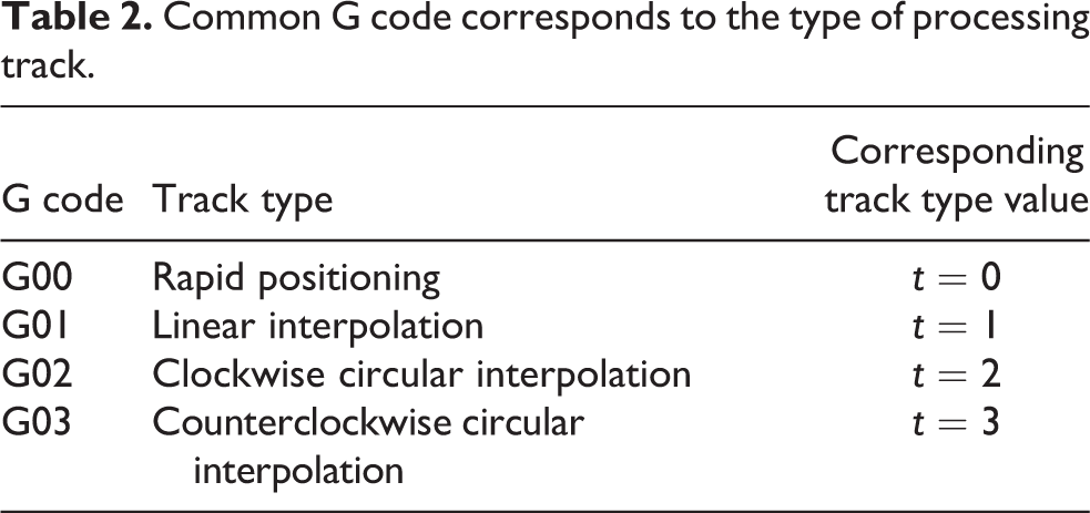
It can be seen that the NC program contains a wealth of workpiece geometry information and workpiece process information, and it has a standard specification format. Therefore, by analyzing the NC program, the tool path information and processing parameter information of the CNC machine tool can be obtained. This program corresponds to the overall machining path length of the machining task and the expected machining time, and can also provide a basis for subsequent processing progress monitoring. The machining path determined by an NC block mainly includes the block number, machining type, size information, and feed information. The block number, size coordinate information, feed rate, and other information can be obtained directly from the block. The type of the machining track needs to be determined according to the type of G code in the block. In this article, the corresponding processing path type definitions for common G codes are shown in Table 2.
Common G code corresponds to the type of processing track.
Database system design
The system uses the QODBC method provided by Qt to connect with the SQL Server database. Qt provides the QSql class to interact with the database system to realize data access management. First need to establish the connection between the application and the database, create a QSql Database object by calling the add Database function, and set the database driver type, server address, database name, port number, login name, password, if the database can be successfully opened, the connection is successful. Otherwise, you will be prompted not to open the database and display the cause of the error. After the connection is established, you can use the QSql Query class to execute the SQL statement to achieve database operations. The model represents the data of the application, the view represents the user interface, the controller represents the response to the program interface according to the input, in Qt, the view and the controller are combined together, and a proxy is added to enable the user to customize the data entry. Display and editing mode, as shown in Figure 2.

Qt’s model-view-controller (MVC) design pattern.
The machining state of the CNC machine tool will change constantly during the running process, which will generate a lot of dynamic information. To realize the real-time monitoring of the machine tool processing status data and the workshop processing tasks, it is necessary to store the collected data and the workshop task implementation in real time. Update, so the database needs to be stored and managed for system data. In this article, the E-R graph model is used to design the conceptual database of the system database according to the system requirements. This system is mainly for data acquisition and monitoring of CNC machine tools in the workshop. Therefore, the system data entity set can be summarized into the following categories: machine static information, machine tool dynamic information, machining time information, machine tool alarm information, machining task information, machining process information, processing step information, NC program information, and machine tool maintenance records.
Data acquisition monitoring module analysis
The information collection module interface mainly includes the machine tool list to overview the status of the workshop equipment, as shown in Figure 3, which can realize the functions of machine condition monitoring, database connection management, machine tool management, real-time data monitoring of various machine tools. The machine tool list interface displays the machine number, IP address, name, machining status, emergency stop status, and alarm status in real time. Click the “Connect to Database” button to enter the database connection management dialog box, you can modify the default database information, including the database server address, database name, port number, login name, and password. “Machine Management” allows you to add, edit, and delete machine lists in the current shop. The status bar displays the database connection status, monitoring status, and agent status. Before starting the acquisition, you need to set the Agent and modify the adapter parameters in “Agent.cfg” to correspond to the machine address and port number. When the user clicks “Start Acquisition,” the system first starts the adapter and the Agent service. After the startup is successful, the data collection is started and the monitoring interface display is updated.
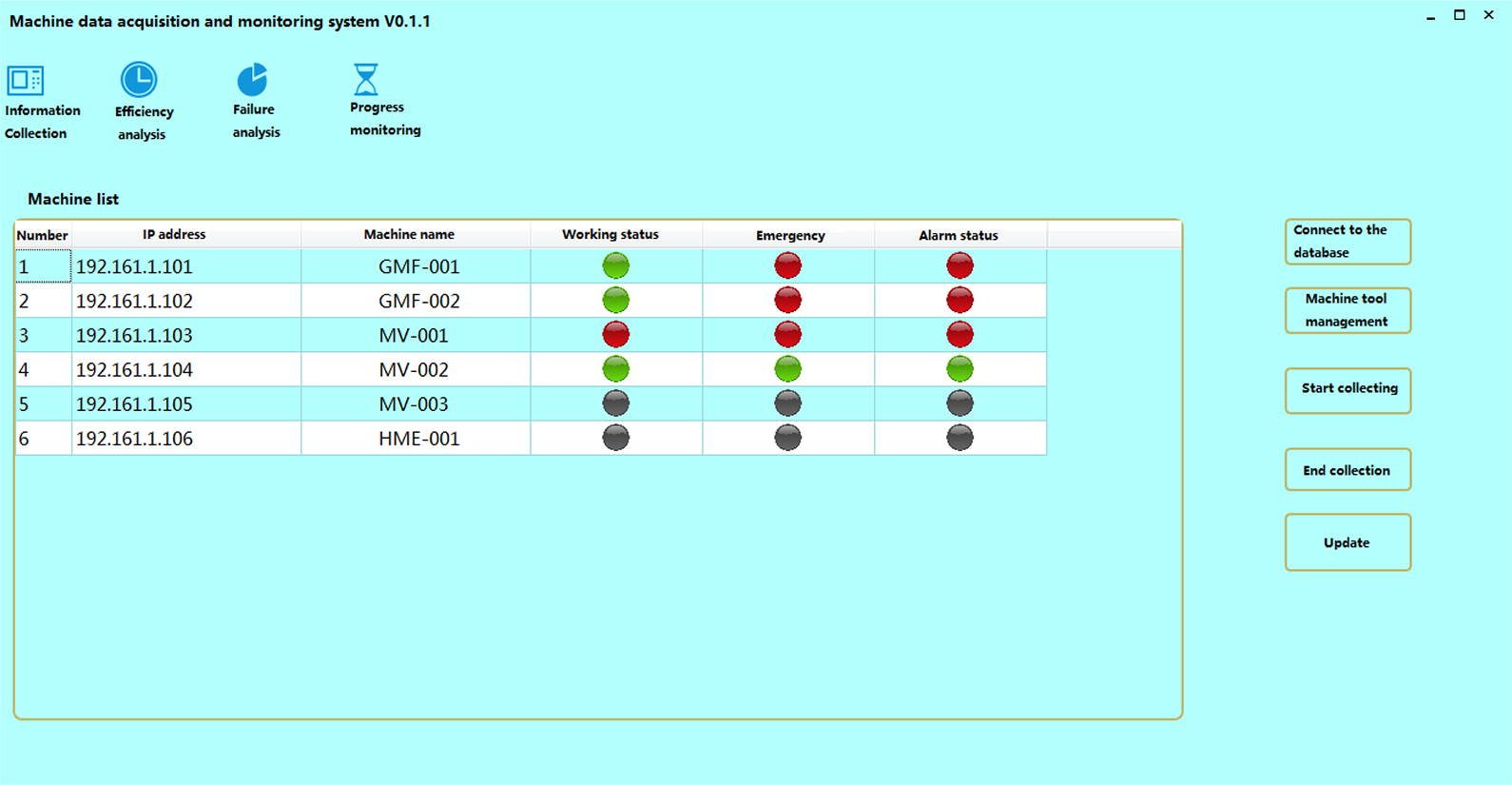
Information collection interface.
For a single machine monitoring function, by double-clicking the corresponding machine tool in the machine list, the single machine monitoring interface is shown in Figure 4. It includes six types of machining status, spindle control, NC program, parameter setting, alarm information, and system information. Comprehensive and detailed monitoring of all types of machine information. The machining status interface mainly displays information such as the overall status of the machine tool, coordinate position, and spindle speed feed. The spindle monitoring interface mainly monitors the machine coordinate, spindle status, and load status. The NC program interface is the program number and block that the machine is executing. The parameter setting interface monitors the tool compensation, workpiece zero point, etc. The alarm information interface displays the machine alarm type, alarm number and alarm information content, and the system information displays the basic information of the machine tool.

Single device monitoring interface.
Experimental data and comparison
This section describes the monitoring method of CNC machining tasks through examples. A workshop needs to carry out the NC machining and processing tasks of a product part. According to its process route, the NC machining task includes three processes. The process I contains two CNC machining programs, the machine tool is machine tool 1 and the process II contains three. A numerical control machining program, the machining machine is a machine tool 2; the process III includes three numerical control machining programs, and the machining machine tool is a machine tool 3. This article introduces the monitoring methods of numerical control machining tasks from three aspects: numerical control machining task modeling, machining task working time prediction, and processing task progress monitoring. After the machining task is modeled, the processing task can be predicted according to the task model. According to the CNC machining task working time prediction method, the auxiliary step, the measuring step and the processing step time in each process are respectively calculated.
Taking the process monitoring process of process II in this processing task as an example to verify the progress monitoring method of NC machining task. According to the numerical control machining task model, the second numerical control program of the process II processing step is being executed, and the machining position of the numerical control program is monitored at a certain time. The theoretical time in the table indicates the theoretical time when the numerical control program executes to the position. The theoretical progress is the processing progress of the current NC program. The actual time is the actual processing time of the program, and the actual progress is the ratio of the actual time to the actual total time. As shown in Table 3, it can be seen that the processing progress monitoring result of the method and the real-time processing progress error of the actual situation are small, and the monitoring of the processing progress can be accurately performed.
Partial processing progress monitoring results of the NC program.

This chapter mainly studies the monitoring function module of CNC machining tasks in the workshop. Firstly, based on the object-oriented Petri net, the NC machining task model is established. Then based on the characteristics of each element in the NC machining task model, a program processing time algorithm based on NC program analysis and a preventive maintenance cycle time algorithm of the machine tool are proposed to realize the processing task working hours. Based on the processing task model, combined with the real-time information of the task, the task processing progress is monitored in real time, and the completion rate and remaining time of the processing task are calculated. Finally, the processing progress method proposed in this article is verified by an example.
Experimental results analysis and comparison
Combined with the implementation method of the previous functional modules, this section will take the operation of the system in a workshop of a machine tool manufacturing enterprise in Nantong as an example to introduce the practical application of the numerical control machine tool data acquisition and monitoring system, including the system user identity verification and data. Acquisition and control, efficiency analysis and fault analysis, processing progress monitoring function module. There are six machine tools in the target workshop, and the construction of the local area network in the workshop has been completed, which realizes the networking of the machine tool through the Ethernet port. The processing efficiency of CNC machine tools is an important indicator that enterprise managers are very concerned about. It can directly reflect the production status of enterprises, enable managers to intuitively understand the use of machine tools, find out the weak links in production, and improve the entire workshop.
The user can select the start time and the end time to perform a query analysis on the machine efficiency in the time period. The statistical types include date and month. The query information includes equipment startup time, cutting time, and fault time. The system working hours and processing qualification rate can be input by the user or imported from the MES system database. The operating rate, usage rate, and OEE information can be automatically Complete the calculation. The overall efficiency map is the overall efficiency of all machine tools in the shop. Click on the “Draw” button to visualize the machine time and efficiency, as shown in Figure 5. After selecting the machine in the list, click “Machine Analysis” to make a line drawing of the operating rate, usage rate and OEE efficiency change of a single machine during this time period, as shown in Figure 6, which can be used for the equipment within the time period.

Machine time chart.

Single machine efficiency chart.
The statistics of the machining time of the machine are mainly based on the change of the machining state of the machine. The machining state of the CNC machine can be divided into three states: shutdown, start-up, and machining. The duration of different states of the machine can be obtained according to the change of the machine state record.
Conclusions
To put forward the research significance and research content for the problems and actual needs of the current CNC machine tool data acquisition and monitoring system, summarize the data acquisition characteristics of common machine tools, determine the data acquisition method of the system, and determine the system network. The connection method was analyzed and determined. The overall architecture of the system was designed according to the system requirements. The main functional modules and key technologies of the system were introduced. According to the characteristics of NC machining tasks in the workshop, the monitoring method of CNC machining tasks in the workshop is proposed. The task and organization of NC machining tasks are analyzed, and the hierarchical object-oriented Petri net model of machining tasks is established. Based on the processing task model and the estimated working hours of the task, combined with the real-time data driving of the workshop, the tracking and monitoring of the processing task progress is realized. A machining step time calculation method based on NC program analysis is proposed for the machining step in the task model. The machine tool failure and preventive maintenance factors are considered in the task, and the preventive maintenance cycle of the machine tool is calculated according to the machine tool failure information. The processing time of the task is predicted by combining the processing time of each element. Based on the above system framework and function implementation method, the development of the prototype system for data acquisition and monitoring of CNC machine tools was completed, and the system was verified in the target workshop to prove the effectiveness of the system.
Footnotes
Declaration of conflicting interests
The author(s) declared no potential conflicts of interest with respect to the research, authorship, and/or publication of this article.
Funding
The author(s) disclosed receipt of the following financial support for the research, authorship, and/or publication of this article: This research is supported by Anhui Provincial Natural Science Foundation (1808085ME126), the Provincial (Key) Natural Science Research Project of Anhui Colleges (KJ2017A538), Talent Research Fund Project of Hefei University in 2016-2017(16-17RC25), the Support Program Project for Excellent Youth Talent in Higher Education of Anhui Province (gxyq2018069).