
Abstract
Traveling along straight lines and headland turning are two common motions during the automatic guidance of agricultural machines. However, most studies focus on accurately following parallel tracks in the field and seldom consider the maneuvers at the end of each row. Moreover, numerous studies have mainly focused on planning the global trajectories in the entire field to increase field efficiency, and very few works are related to maneuver generation and vehicle control in headlands. In this study, a feedforward-plus-proportional–integral–derivative controller for a differential drive robot in headland turning was developed. The feedforward-plus-proportional–integral–derivative controller consisted of a feedforward and a feedback loop. The feedforward loop was designed based on the heading errors of a lookahead point on the planning path. The feedback loop was designed based on radial errors to improve the tracking accuracy. Field comparison tests of feedforward, feedback, and feedforward-plus-proportional–integral–derivative controllers were conducted. Experimental results showed that the feedforward-plus-proportional–integral–derivative had better tracking results and took less turning time.
Keywords
Introduction
Mobile robots play a significant role in many agricultural applications as they reduce human labor and enhance the operational safety. The need for autonomous navigation systems of mobile robots has been recognized in different agricultural tasks such as planting, spraying, fertilizing, cultivating, harvesting, thinning, weeding, and inspection. 1,2 Traveling in straight lines and headland turning are two common motions during the automatic guidance of an agricultural machine. Completely autonomous guidance would require the robot’s capability to make turns in the headland and enter the next operation row. Several factors such as space availability, vehicle limitations, obstructions, and time taken to turn have to be taken into account when controlling robot during headland turning. However, most studies focus on accurately following parallel tracks in the field, and seldom consider the maneuvers at the end of each row. 3 –6 Miller et al. have reported that the space required to turn at the headland and the time spent in turning significantly affect the field efficiency. They also report that the damage of crops owing to improper headland turns affects productivity. 7 To benefit from fully automated solutions and, therefore, reduce the operator’s workload, the problem of maneuver automation in headlands needs to be studied with meticulous care.
Kise et al. tested headland turns using a spline function path planning method on a tractor using a global positioning system-based guidance system. The method guided the vehicle along the desired path with an error of less than 20 cm in lateral deviation. 8 Hague et al. used vision-based guidance in combination with dead reckoning to guide a vehicle through crop rows. The guidance system detected the end of crop rows using the absence of crop-row information from the vision and distance information in dead reckoning. The vehicle was able to execute a U-turn at the headland. 9 Subramanian et al. developed a turning maneuver for an autonomous vehicle from a row into the adjacent row at the headlands of citrus groves. The results showed that the vehicle could turn into the headland at the end of a row, navigated the headland, and turned into the adjacent row without any contact with the alleyway trees. 10 Cariou et al. addresses the problem of path generation and motion control for the autonomous maneuver in headland of a farm vehicle with a trailed implement. A reverse turn planner is firstly investigated, based on primitives connected together to easily generate the reference motion. Then, both steering and speed control algorithms are presented to accurately guide the vehicle–trailer system. 11 In the literature, numerous studies have mainly focused on planning the global trajectories in the whole field to increase field efficiency, 12 –19 and very few works are related to maneuver generation and vehicle control in headlands. Most of the previous research focuses on wheel-type robots owing to their applicability to a wide range of challenging situations by developing control techniques. However, crawler-type tractors are also used in some agricultural fields because of their high traction and low ground pressure. 20 Moreover, many of the previous methods either use open-loop control, which is quite sensitive to measurement errors and disturbances, or are highly model dependent, making the controllers very complex and hard to implement in practice.
Proportional–integral–derivative (PID) controllers are the most employed controllers in industry and robot field owing to their relative simplicity and satisfactory performance for a wide range of processes they are capable to provide. 21 However, for robot’s headland turning, most of the path planning maneuvers consist of curve paths. 16 If the robot tracks such a path, it must perform direction changes very often, which requires the controller to correct tracking error in rapid respond. PID controllers take corrective action only after the errors were generated. This limitation will lead to large errors or even instabilities during the robot headland turning. One of the most significant improvements both for the set point following 22 and for the disturbance rejection task 23,24 is to incorporate feedforward control with knowledge about the system and using the PID to control error. Some feedforward plus feedback control schemes had been designed for path trackings, such as path curvature and longitudinal force inputs, 25 driver steering command, 26,27 explicit functions of the reference path, 28 and a certain “lookahead” point in front of the vehicle 29 –31 were used to design the feedforward controllers, whereas dynamic feedback linearization, 32 fuzzy logic, 33 and adaptive PID 34 were used to design feedback controllers. Same with the previous work, 29,30 a lookahead point was chosen to design the feedforward controller in this article. Specially, the orientation error of the lookahead point was used to make the controller more suitable for robot headland turning. Meanwhile, considering a simple but effective approach to implement the feedback controller. A proportional–integral algorithm was used to make it simpler and steadier in the steady-state in the case of noisy data compared with the traditional PID.
The main contribution of this article was applied to the feedforward-plus-proportional–integral–derivative (FPID) controller for solving the agricultural robot headland turning problem. The FPID controller designed in this study is model-independent and easy to implement while still improves path tracking accuracy. Field comparison tests were conducted to examine the controllers’ performance regarding headland tracking accuracy, turning time, and next row lateral errors.
Materials and methods
Research platform and navigation hardware
A crawler-type robot platform was used in this research. Figure 1 shows the research platform, a Komodo-01. Table 1 presents its specifications. Global Navigation Satellite System (GNSS) antennas and a Trimble BD982 receiver were used as navigation sensors to determine position errors to evaluate the autonomous navigations. To obtain the absolute position of the robot platform, a base station was used with a positioning accuracy of ±2 cm. A laptop PC (Lenovo, T460s) was used for performing high-level algorithm processing and managing the overall guidance system. Qt Creator 5.7 was used for implementing the algorithms for navigation and graphical user interface for analyzing the algorithms’ behavior in real time. A microcontroller was used for low-level control operations such as converting PC’s digital command signal to analog signal to operate the left and right motor and processing the encoder data. The PC and microcontroller were communicated through RS232. Figure 2 shows a schematic diagram of the robot platform.

Research platform (Komodo-01).
Specifications of the tracked robot.

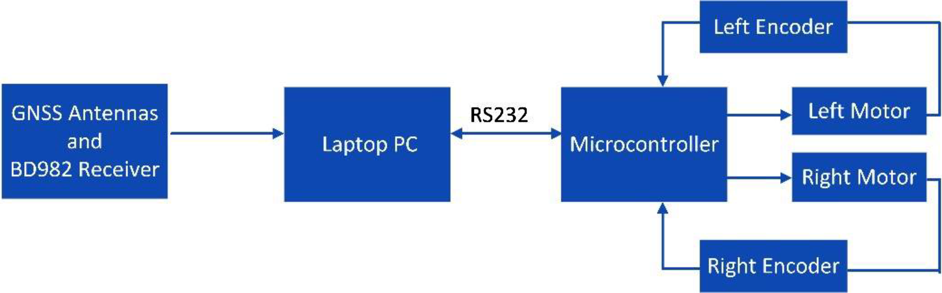
Schematic diagram of the robot platform.
Kinematics of the differential drive mobile robot
Kinematics is the study of motion without considering the forces. A tracked mobile robot can be seen as a special case of a wheeled robot with the differential drive. The difference is the robot’s better maneuverability in rough terrain and its higher friction in turns, owing to its tracks and multiple points of contact with the surface. 20
As Figure 3 shows, the configuration of the robot platform is represented by the generalized coordinate constraints

Kinematics model of differential drive robot.

and the kinematic model in the world frame is given by

vl
, vr
, and


from the equations above, if
Headland turning controller design
The FPID consists of a feedforward loop and a conventional feedback loop. Input to the feedforward is the heading deviation

Block diagram of the FPID controller. FPID: feedforward-plus-proportional–integral–derivative.
The FPID controller geometry used in this work is represented in Figure 5. Consider a differential drive robot taking a left turn on a flat surface. The planning path is created as a circular arc and represented as a subset of the points referred to as “navigation points.”

FPID controller geometry. FPID: feedforward-plus-proportional–integral–derivative.
Find the current position of the vehicle in the global coordinate system
Find the closest point A

Starting from point A, the lookahead point G

Based on the kinematics model, the robot platform with differential wheel control turns by using different wheel speeds. Let 
where
From (3), (4), and (7)

where
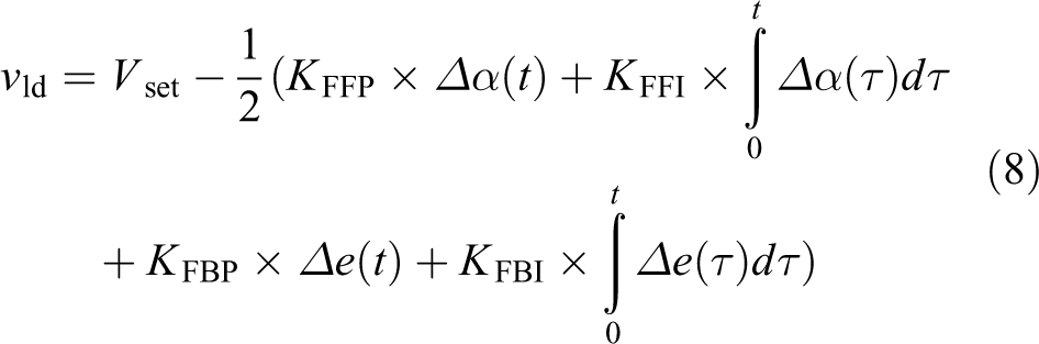
In this study, the FPID controller focuses more on steering than on controlling the linear velocity. Thus, equation (10) was applied to computing a new motor linear velocity if the original value exceeds a motor’s maximum forward linear velocity

where
Results and discussion
To test whether the proposed algorithm works practically on the differential drive robot platform and to compare the performance of the FPID, feedforward, and feedback controllers, several experiments are made for the robot platform. The FPID, feedforward, and feedback controllers are implemented in C++ and tested on a laptop computer with a Core i5 2.5 GHz processor and 4G RAM. The GNSS updates the robot position at about 20 Hz and the controller runs at 10 Hz on average. Experiments were conducted to test on flat paved ground. The robot was run at an average speed of 0.8 m/s for the straight path and it was slowed down to an average of 0.2 m/s for the headland turning. The feedforward and feedback controllers were actually the feedforward and feedback loops of the FPID controller, respectively, and they were tuned to an optimal level by trial and error after the other loop was disconnected. In the feedforward controller tuning process, the lookahead distance was fixed and the parameters were then tuned manually. The feedback controller was also using the manual tuning method. Two straight reference paths were obtained by GNSS and a semicircle arc with 1-m radius reference path was created using the Dubins algorithm based on planning points obtain by GNSS. 35 For each controller, three turnings were performed to ensure replication, resulting in a total of nine test turns.
Headland turning consists of two parts. In the first part of the process, the robot starts tracking the predefined path using the controllers presented in this work. Radial errors were calculated using equation (11). The yaw angle of the robot was monitored using the GNSS. In the second part of the process, when the robot had turned by more than 165° with respect to the initial heading angle before turning, the straight-line path-tracking controller was used instead. The last 15° of rotation was performed in this part using the straight path-tracking algorithm so that the vehicle does not turn more owing to momentum. Lateral errors instead of radial errors were calculated based on the robot center to the straight path. The details of the controller design were presented in reference. 36 Therefore, any lateral error in entering the new row is corrected using the straight-line path-tracking algorithm

where
Figure 6(a) shows the comparison of the performance of the feedforward, feedback, and FPID controllers in the first part of the process. The average radial errors of the feedforward, feedback, and FPID controllers were, respectively, 0.3844, 0.6867, and 0.3925 m, while the average standard deviations (SDs) were 0.4050, 0.7295, and 0.2872. The average root mean squares (RMSs) were 0.5574, 1.0005, and 0.4865, while the maximum radial errors were 1.3709, 2.2953, and 0.8284 m. It was noted that, in the first part of the turning process, the feedback controller had the worst performance. The feedback control reacted only to the process error and took corrective action only after the disturbances had affected the process and generated an error. 37 This time lag before the deviation of output occurs will enlarge the errors or even create instability of the system during the first part of turning. In contrast, the feedforward and FPID controllers predicted the steering error using the lookahead point and took corrective action before the disturbance entered into the process. Therefore, both the feedforward and FPID controllers had better performance than the feedback controller in this part. However, a pure feedforward controller is an open-loop control and is not self-correcting. If the input adjustments failed to produce a correct output, then the process will continue to produce the wrong output. The FPID balances the capability of the feedforward controller to take preemptive control actions for a heading deviation, while it permits the traditional feedback control loop to provide set point tracking capability and rejects all other disturbances and external influences that are not measured. In addition, the feedforward loop in the FPID minimizes the level of compensation required by the steering feedback, thus reducing the tracking errors and allowing for less overall control effort. Overall, the FPID controller results in lower tracking errors compared with the feedforward and feedback controllers in the first part of turning. Moreover, as Figure 6(b) shows, it was also found that under the same robot forward velocity and optimal control gain for each controller condition, the FPID controller had less turning time than that of the other controllers in the first part of turning.

(a) Comparison of performance in the first part of turning. (b) Turning time comparison.
Figure 7 shows the comparison of performance in the second part of turning in the second part of the process. The average lateral errors of the feedforward, feedback, and FPID controllers were 0.4157, 0.0701, and 0.2909 m, respectively, while the average SDs were 0.2839, 0.1154, and 0.1705. The average RMSs were 0.5026, 0.1412, and 0.3371, while the maximum radial errors were 0.9979, 0.1532, and 0.6524 m. From the plots of the second-part performance comparison, it was found that, in general, the path tracking of the feedback controller had a better performance than that of the other two controllers. One of the main reasons for this was that large radial errors occurred when the robot came close to the top of the headland turning owing to the feedback controller’s time lag errors correction. This large error causes a very large differential drive control for the robot’s left and right tracks and makes the robot’s heading to change suddenly, which causes that the second part of turning becomes active earlier than that with the other two controllers. Therefore, the robot enters to the straight path-tracking mode with less lateral errors. However, owing to the large radial error in the first part of turning, as shown in Figure 8, the feedback control mode occupied the largest headland space. In contrast, the FPID occupied the smallest headland space. By integrating the feedforward and feedback controllers, the resulting FPID controller showed its capability in compensating both the lookahead point heading errors and radial tracking errors effectively.

Comparison of performance in the second part of turning.

Reference path and the actual position of the robot.
Conclusions
An FPID headland-turning controller for a differential drive robot was developed in this study. The controller consisted of a feedforward loop and a feedback loop. The feedforward loop was designed based on the heading errors of a lookahead point on the planning path and the feedback loop was designed based on radial errors to improve the steering accuracy. Field comparison tests of the feedforward, feedback, and FPID controllers were conducted. Experimental results showed that the FPID could provide accurate steering control and could reduce the radial tracking error from a finely tuned feedforward and feedback loop. Moreover, the FPID headland turns decrease the proportion of the field area that constitutes the headland area and, consequently, the proportion of low-productivity area, which results in economic benefits. In our study, the robot headland-turning velocity was set as fixed. However, it was found that the feedforward loop in the FPID steering command becomes increasingly sensitive as the vehicle speed increases. A common fix for this issue is to scale the lookahead distance with the vehicle speed. This should be done in future work. Moreover, attention must be paid to providing an accurate kinematic model that considers more variations, such as the sideslip factor.
Footnotes
Acknowledgement
The authors are grateful to the student Zhao Yunxia and Lin Guchen for their help to the experiments.
Declaration of conflicting interests
The author(s) declared no potential conflicts of interest with respect to the research, authorship, and/or publication of this article.
Funding
The author(s) disclosed receipt of the following financial support for the research, authorship, and/or publication of this article: This work was supported by the International S&T Cooperation Program of China (2015DFG12280) and the Science and Technology Planning Project of Guangdong Province, China (2016B020205003).