
Abstract
The innovative three-dimensional humanoid biped gait planning method using geodesics is introduced in this article. In order to control three-dimensional walking, the three-dimensional linear inverted pendulum model is studied in our energy-optimal gait planning based on geodesics. The kinetic energy of the three-dimensional linear inverted pendulum model is calculated at first. Based on this kinetic energy model, the Riemannian metric is defined and the Riemannian surface is further determined by this Riemannian metric. The geodesic is the shortest line between two points on the Riemannian surface. This geodesic is the optimal kinetic energy gait for the center of gravity because the kinetic energy along the geodesic is invariant according to the geometric property of geodesics and the walking is energy-saving. Finally, a simulation experiment using a 12-degree-of-freedom biped robot model is implemented. The gait sequences of the simulated RoboErectus humanoid robot are obtained in the ROS (Robot Operating System) Gazebo environment. The proposed geodesics approach is compared with the traditional sinusoidal interpolation method by analyzing the torque feedback of each joint of both legs, and our geodesics optimization gait planning method for three-dimensional linear inverted pendulum model walking control is verified by the assessment results.
Introduction
Boston Dynamics has recently developed a new version of a humanoid robot, Atlas, which can walk in snow, pick up objects and stand up after a fall (see http://www.bostondynamics.com/robot_Atlas.html). The ability of Atlas to stay upright while navigating uneven terrain and adjusting for unexpected complications illustrates that it is very important to perform dynamic gait planning and control for a humanoid robot. Researchers perform optimal dynamic gait planning to ensure that the humanoid robot can walk stably and efficiently. The laser-based perception, footstep planning, and walking control of a humanoid robot have been integrated for navigation over previously unknown rough terrain. 1 Based on the three-dimensional linear inverted pendulum model (3D-LIPM), energy-efficient gait planning and control is established for biped robots which utilizes the allowable zero moment point (ZMP) region. 2 The compliance controller has been designed to reduce the energy consumption by exploiting the natural dynamics. 3 The gravity-compensated inverted pendulum mode is established by considering the free leg or swing leg dynamics based on the predefined trajectory and it helps to keep the ZMP within the presumed area and makes the robot walk more stably. 4 The required torque of each actuator is also studied by adjusting walking parameters. 5 A low-energy-cost reference trajectory for a biped robot is given by defining ballistic motion and impulsive control at dual support instances. 6 Several cost functions of energy consumption have been introduced in order to extend the dynamic stable walking method to level ground and uphill slopes. 7 –9 In the meantime, gait synthesis of humanoid biped locomotion has been regarded as an optimization problem with some constraints, for example ZMP constraints for dynamically stable locomotion, internal forces constraints for smooth transition, and geometric constraints for walking on an uneven floor or sloping surface. 10 Many researchers 11 also use genetic algorithms to do optimal gait planning for humanoid robots. Passive walking is a popular strategy to make the humanoid robot walk energy-efficiently. Mass distribution has been tuned for a passive dynamic walker to find the optimal manifolds to maximize walking speed and stability. 12 A planar bipedal robot is designed and this robot can exploit its own natural dynamics during critical stages of its walking gait cycle. 13 The energy-efficient human-like walking is obtained by generating a straight-legged walking pattern for a biped robot using up-and-down motion of the upper body. 14
Two approaches are included in gait planning. One approach is to use precise dynamic parameters of a robot, such as mass and inertia of each link, 15 –17 and the dynamics of the robot is obtained using Newton–Euler or Lagrange dynamics equations. The other approach is to use the linear inverted pendulum model (LIPM) 18, 19 and regard the dynamics of the LIPM model as the whole humanoid robot dynamics. In this article, 3D-LIPM is studied using the geodesics method. A geodesic is the shortest line between two points in Riemannian space. The straight line in Euclidean space is an example of a geodesic. The distance metric is defined 20 and used in the optimal mechanism design of the manipulator. The Bezier curve in Riemannian space is calculated to solve the problem of robotic workspace fitting. 21 By changing the original constant kinetic energy, the optimal smooth trajectories for a set of mobile robots are generated. 22 Generally speaking, all existing works are on rigid body motion with one degree of freedom.
The two-dimensional linear inverted pendulum model (2D-LIPM) is studied using geodesics 23 but the results have not been mapped onto the robot gaits and the energy-saving gait is in fact obtained based on category one (the full dynamic parameters model) which is mentioned above and this optimal gait is in single support phase for swing leg only. In this article, we use a geodesic method to study optimal-energy gait planning based on 3D-LIPM. The dynamic model of 3D-LIPM is established first. The Riemannian metric based on system kinetic energy is defined second. Then optimal-energy gait planning in both single and double support phase is carried out based on geodesics. The optimal gait of 3D-LIPM is further converted into the 12 joints of the two legs to obtain the final gaits of the robot. The simulation experiments are implemented to verify the geodesic gait planning method.
Geodesic and 3D-LIPM gait planning
Concept of a geodesic
A geodesic is the shortest path between two points in a curved space (Riemannian space) and its equation can be obtained using covariant derivation. 24, 25 The straight lines between two points in Euclidean space are intuitive examples of geodesics. On a sphere space (curved space), the images of geodesics are the great circles between two points on the sphere surface. If we regard the energy of the robot system as the curved space, then the distance between two points (start position and end position) in this curved space will be measured by the energy. So the geodesic between two points will be the minimal energy path. Another attribute of geodesics is that the distance from f(s) to f(t) along the geodesic is proportional to |s − t|, that is, the covariant derivative of the tangent vector along the geodesic is zero. For the multi-rigid robotic system, once again, if we regard the kinetic energy as the curved space, the distance between two points will be measured by the kinetic energy. The variation of kinetic energy will be constant: there will be no jerk. So the energy-saving gait of a humanoid robot can be obtained using a geodesic method. The equation of the geodesic is

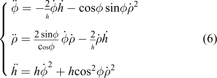
where s is the arc length of the curve, and θi is the curve coordinate, for

where gkm, gjm, gkj (j, k, m = 1, 2, …, n) are the entries of the Riemannian metric, and gmi is the element of the inverse matrix of the Riemannian metric matrix. Christoffel symbols satisfy the symmetry relations
3D-LIPM gait planning
The designed 3D-LIPM trajectory generator for the humanoid robot uses four different interpolation functions to describe the motions. First is the cosine velocity curve. Second is the Bezier curve. The third is the cubic polynomial. The fourth is the one provided by Kajita. 19 The first three methods use pre-fixed curves and are efficient for creating gaits. However, they have no physical meanings relating to the intrinsic characteristics of humanoid walking, a geodesic between two points is the minimal energy path and has an explicit physical meaning. So we introduce the geodesic for 2D-LIMP gait planning at first and then we extend this method for 3D-LIPM gait planning.
Optimal energy gait planning for 3D-LIPM
Riemannian metric of 3D-LIPM
Humanoid robot gait planning in both the sagittal plane and the frontal plane can be modeled as a 3D-LIPM. Figure 1 depicts the 3D-LIPM humanoid model which consists of a point mass and a massless telescopic leg. The position of the point mass

where φ is the angle between the inverted pendulum and its vertical projection line, ρ is the angle between the x-axis and the vertical projection of the inverted pendulum, h is the length of the inverted pendulum, and m is the mass of the point mass of the inverted pendulum. The kinetic energy of this 3D-LIPM system is

We set point mass m = 1, ignore the coefficient 1/2 in the above equation, and rewrite the kinetic energy into Riemannian metric form


3D-LIPM model.
Geodesic of 3D-LIPM
The geodesic equations (1) and (2) for 3D-LIPM are also determined by a Riemannian metric. The Riemannian metric is an intrinsic measurement index. It can be obtained according to the kinetic energy metric in (5). The 3 × 3 matrix in (5) is the Riemannian metric matrix, and the elements of this matrix are the Riemannian metric coefficients corresponding to
The geodesic equation will be converted into a standard state-space equation in order to solve this differential equation in MatLab. So the final geodesic equation is

When the initial condition and final condition are given, we can find a geodesic between the two points. When the inverted pendulum is moving along this geodesic, the kinetic energy is constant and minimized.
Geodesic of 3D-LIPM in a whole walking cycle
The 3D-LIPM-based humanoid robot walking considers the gaits in both the sagittal plane and frontal plane. The support leg will exchange one time between single support phase and double support phase during a whole walking cycle of the humanoid robot. A whole walking cycle of the 3D-LIPM is shown in Figure 2. We give six key points during the whole walking cycle. In Figure 2, φ0, ρ0, and h0 is the initial point of the walking cycle, φ1, ρ1, and h1 is the end point of the single support phase, and φ2, ρ2, and h2 is the initial point of the next single support phase after support leg exchanging (the different line widths of h1 and h2 are used to indicate the support leg exchanging). We assume that the leg exchanging is finished in a very short amount of time. Further, φ3, ρ3, and h3 and φ4, ρ4, and h4 are the points before and after support leg exchanging (double support phase) respectively; φ5, ρ5, and h5 is the final point of the whole walking cycle and its state is same as the start point φ0, ρ0, and h0. The gaits between these points can be generated using geodesics. A geodesic is the shortest line between two points on a Riemannian surface. The Riemannian surface is determined by the Riemannian metric. Once again, we define the kinetic energy as the Riemannian metric, and then the distance between two points on this surface is measured by the kinetic energy. We can connect these key points (from φ0, ρ0, and h0 to φ5, ρ5, and h5) using geodesics on a Riemannian surface whose metric is the kinetic energy: then the optimal kinetic energy gait during a whole walking cycle is obtained.

Whole walking cycle of 3D-LIPM.
Optimal gait planning by geodesic
The traditional gait pattern generation method is to use the cosine velocity curve for the trajectory planning of the center of mass of the 3D-LIPM model. The cosine curve is simple in mathematics and makes the planning easier. But the cosine curve is not able to reveal the intrinsic invariance of the robot walking especially when taking into account human walking. Human walks use energy-saving gaits naturally. The geometric property of geodesics represents this intrinsic performance to some degree and it can be used for gait pattern generation. We assume that the initial and final points of a 3D-LIPM inverted pendulum are φ0 = 75°,

Geodesic gait for 3D-LIPM from state 0 to state 1.

Geodesic gait of 3D-LIPM from state 2 to state 3.

Geodesic gait of 3D-LIPM from state 4 to state 5.
Inverse kinematics of humanoid robot
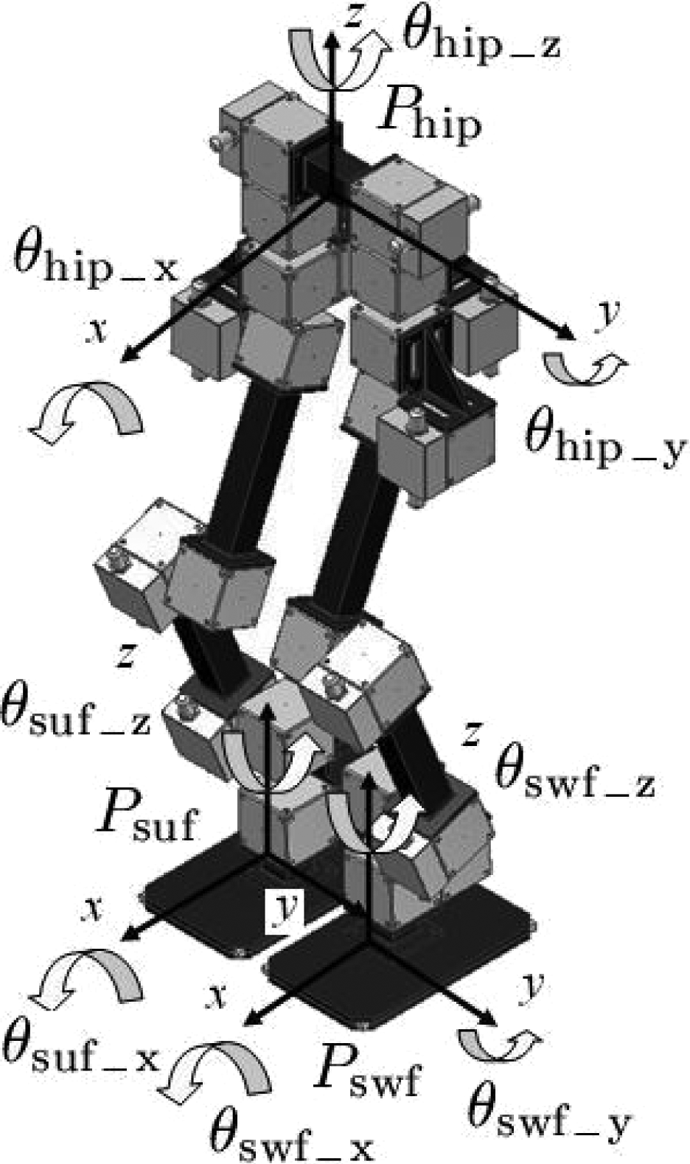
The geometric parameters of the robot legs are shown in Figure 6. The known parameters for inverse kinematics are positions and orientations in roll, pitch, and yaw of support foot, hip, and swing foot (Figure 7) respectively as follows:
support foot position,
support foot orientation,
hip position,
hip orientation,
swing foot position,
swing foot orientation,

Geometric parameters of humanoid robot legs.
Initial conditions of the robot.
These parameters determine the gait characters of the humanoid robot. The goal of inverse kinematics is to obtain the 12 angles of the legs according to the parameters listed above. The calculation of inverse kinematics includes the following steps: use the homogeneous transformation matrix to compute the x-, y-, and z- positions of ankle joints and turn joints of two legs; project the vector from the support ankle to the support turn joint to the Cartesian space defined by roll, pitch, and yaw angles of the support foot; get joint angles of support leg; project the vector from the swing ankle to the swing turn joint to the Cartesian space defined by roll, pitch, and yaw angles of the swing foot; get joint angles of swing leg.
Following these steps, we obtain the inverse kinematics of the humanoid robot. When the robot is walking, this inverse kinematics is updated at 50 Hz.
The algorithm can compute the inverse kinematics of any posture for the humanoid robot. It is a complete solution of the inverse kinematics. The algorithm is very fast because there are no complicated calculations and recursive calls. On a Pentium-4 PC, the algorithm can be performed 10 times in 1 ms.
Simulation experiments of humanoid robot walking
In order to verify the proposed geodesic walking pattern generation method, the simulation is implemented for the RoboErectus Senior AdultSize humanoid robot. Gazebo and the robot operating system (ROS) open-source platform are used for the dynamic simulation. Both the classical sinusoidal interpolation method and the proposed geodesic method are implemented in the simulations.
Humanoid robot and its 3D model
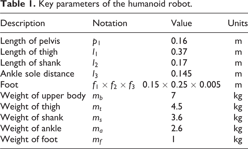
The humanoid AdultSize robot is shown in Figure 8. This robot has gained second place in the RoboCup Humanoid AdultSize league competition. The model of the RoboErectus humanoid robot is created in the unified robot description format (URDF) according to its geometric and physical parameters, and the key parameters of this robot are listed in Table 1. For the gait planning simulation, we assume the upper body is fixed and only focus on the two legs, where each leg has six degrees of freedom. The joint motor we used is the Schunk PowerCube PR70 motor which is shown in Figure 9. The model of the RoboErectus humanoid robot is established in URDF which includes both kinematic and dynamic characteristics of the robot. The model in the Rviz simulator is shown in Figure 10. We use this model for robot walking simulation experiments in the Gazebo environment.

Humanoid robot: RoboErectus Senior. IMU: Inertial Measurement Unitand; AI: Artificial Intelligent.
Key parameters of the humanoid robot.
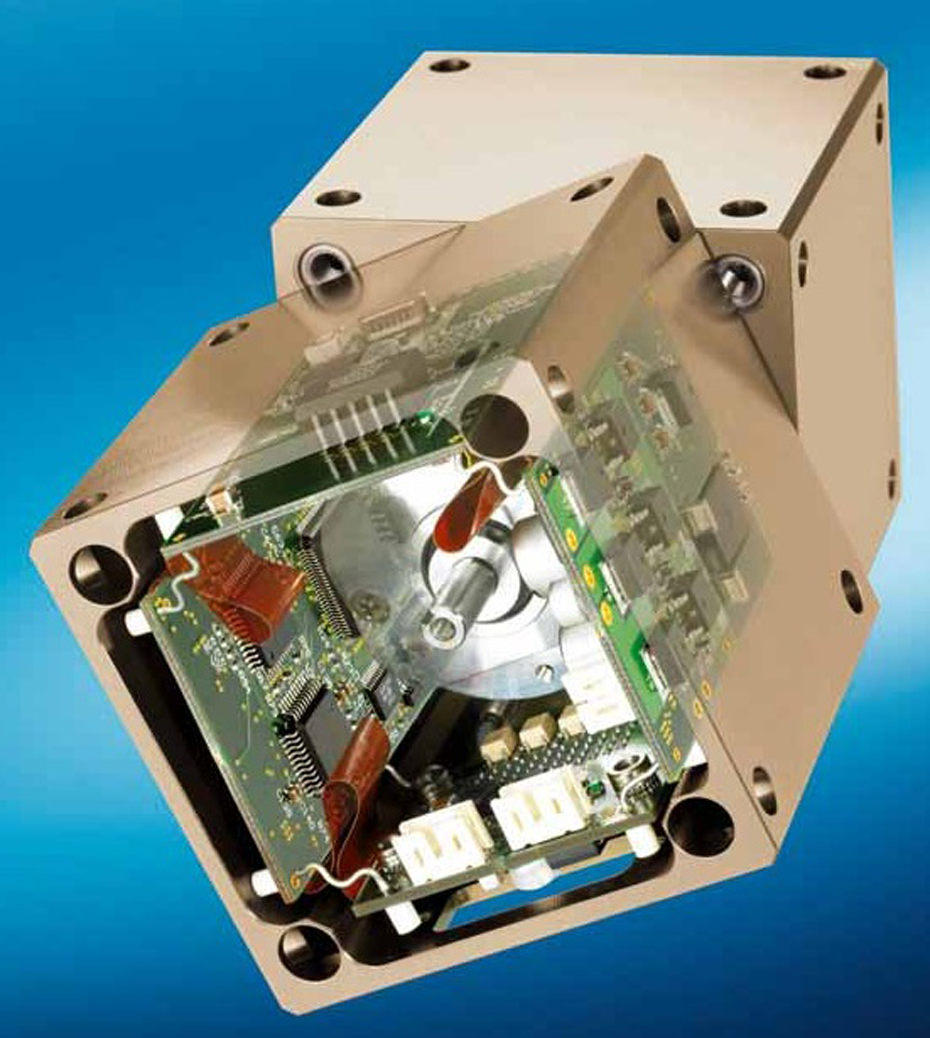
PowerCube PR70.

Humanoid robot model shown in Rviz environment.
Gait planning visualization
The traditionally used method of humanoid gait planning based on 3D-LIPM is to generate a sinusoidal function between the given points. So we implement the sinusoidal interpolation between the former given knots. The sinusoidal function to fit the given knots is

Gait of 3D-LIPM using sinusoidal interpolation.

Gait of 3D-LIPM based on geodesics.
Humanoid robot walking simulation
The three parameters φ, ρ, and h of 3D-LIPM can be obtained by solving the geodesic equation. The inverse kinematics is used to calculate the angles of the 12 joints of the two legs. The humanoid robot walking simulation is implemented in Gazebo. The example of the gait pattern for a straight line is shown in Figure 13. In order to assess and evaluate the efficiency of the geodesic gait planning method, the traditional and most popularly used sinusoidal interpolation method for gait planning is also simulated. The torque feedback from 12 joints of the legs are compared and illustrated in Figures 14, 15, and 16. The thick black lines in the figures represent the torques related to the sinusoidal interpolation method and the thin red lines represent the torques corresponding to the proposed geodesics approach. The sample period is 50 Hz. By comparing the torques for each joint using the sinusoidal interpolation method and the geodesics approach, we find that in Figure 14 the torques of the thigh and knee joints using the geodesics approach are smaller than the torques using the sinusoidal interpolation method. There are no big differences between these two methods for the torques of the turn and hip joints in Figure 15. In Figure 16, the torques in the ankle and foot joints are a little better than the sinusoidal interpolation torques. The differences are not obvious but the results show that the proposed geodesics approach is at least as good as the popular sinusoidal interpolation method. The torque index is only one of the aspects to consider when assessing the abilities of gait planning methods. More experiments will be implemented in the future to further evaluate the proposed geodesics approach.

Walking simulation in Gazebo.
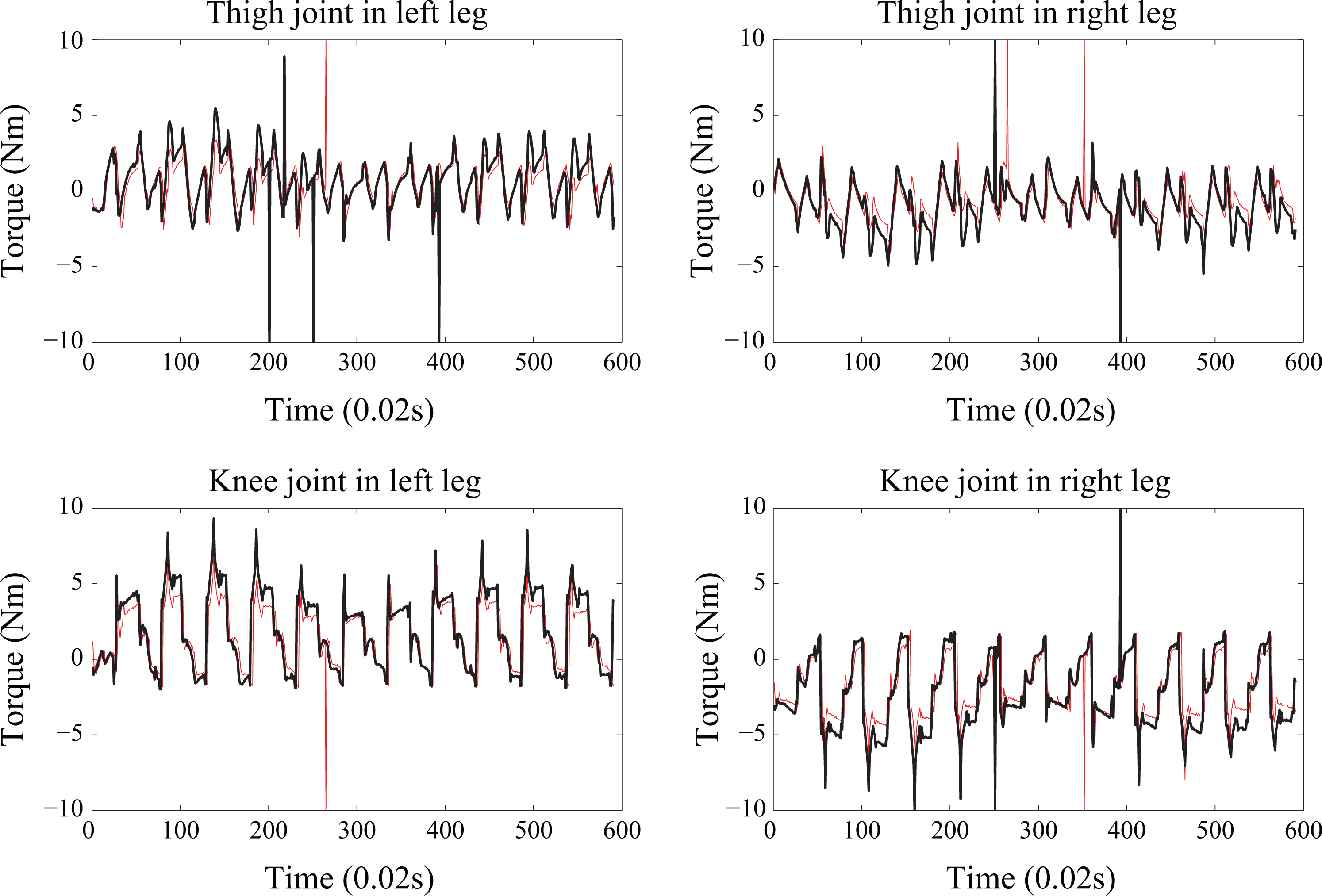
Torques of thigh and knee joints.

Torques of turn and hip joints.

Torques of ankle and foot joints.
Conclusions
The geodesic gait planning method for humanoid robots based on 3D-LIPM is implemented in this article. In order to create a 3D walking gait, 3D-LIPM is studied in our energy-optimal gait planning based on geodesics. The 3D-LIPM model is redefined using three parameters and the kinetic energy of 3D-LIPM is derived using these three parameters. Based on this kinetic energy model, the Riemannian metric is derived and the Riemannian surface is further determined by this Riemannian metric. The geodesic is the shortest line between two points on the Riemannian surface. This geodesic is regarded as the optimal kinetic energy gait for the center of gravity of the 3D-LIPM-based humanoid robot because the kinetic energy along the geodesic is invariant according to the geometric property of geodesics and the walking is energy-saving. By solving the differential equations of the geodesic with the initial and final conditions, the energy-optimal gait of the 3D-LIPM model is obtained. This method is applied to the RoboErectus humanoid robot, which has 12 degrees of freedom for its two legs, at our center. The physical model of this robot is created in the URDF format and the geodesic gait sequences are simulated in the ROS Gazebo environment. The proposed geodesic method for 3D-LIPM walking pattern generation is verified by comparing the simulation results with the traditional sinusoidal interpolation method.
Footnotes
Author note
Author Liandong Zhang is also affiliated to School of Mechanical Engineering, Dalian Jiaotong University, Dalian, Liaoning, China.
Declaration of conflicting interests
The author(s) declared no potential conflicts of interest with respect to the research, authorship, and/or publication of this article.
Funding
The author(s) disclosed receipt of the following financial support for the research, authorship, and/or publication of this article: This research was supported by the Natural Science Foundation of China (NSFC number 51275065) and by the Translational and Innovation Fund from the Ministry of Education, Singapore (MOE2013-TIF-1-G-057).