
Abstract
Large fluctuation, large overshoot, and uncertain external disturbance that occur when an autonomous underwater vehicle is in deep motion are difficult to address using the traditional control method. An optimal control strategy based on an improved active disturbance rejection control technology is proposed to enhance the trajectory tracking accuracy of autonomous underwater vehicles in actual bathymetric operations and resist external and internal disturbances. First, the depth motion and mathematical models of an autonomous underwater vehicle and propeller are established, respectively. Second, the control rate of the extended state observer and the nonlinear error feedback of the traditional active disturbance rejection control are improved by using a new nonlinear function. The nonlinearity, model uncertainty, and external disturbance of the autonomous underwater vehicle depth control system are extended to a new state, which is realized by an improved extended state observer. Third, the improved nonlinear state error feedback is used to suppress residual errors and provide high-quality control for the system. Simulation and experimental results show that under the same parameters, the traditional active disturbance rejection control has a small overshoot, fast tracking ability, and strong anti-interference ability. The optimized active disturbance rejection control and traditional active disturbance rejection control are applied to the deep-variation motion of autonomous underwater vehicles. Results show that the proposed optimal control strategy is not only simple and feasible but also demonstrates good control performance.
Keywords
Introduction
Autonomous underwater vehicles (AUVs) are submersible robots that operate without human intervention and perform various functions. 1 The ocean is rich in mineral, biological, and metal resources. With the rapid development of AUV technology, AUVs have become increasingly important in rescue services, the military, resource survey, seabed mapping, pipeline inspection, fishery, and other fields. 2,3 The requirement for the AUV controller increases with the AUV application. Depth-changing movement is an important part of AUV motion control. AUVs must execute this movement to reach the required depth and perform tasks, such as seabed surveying and mapping of unknown waters, dangerous underwater operations, and seabed target search, all of which impose strict requirements on AUV stability during depth-changing movement. However, AUVs encounter many constraints in practical applications due to landform changeability, terrain complexity, and requirements for AUVs equipped with sonar on the seabed height. These conditions result in high requirements on the stability and accuracy of AUVs as they move deeper into the water. AUVs have many constraints in the process of motion and thus exhibit large inertia and prolonged delay. Therefore, AUVs are prone to overshoot, underdrive, inertia, and delay while in deep motion. 4 Furthermore, AUVs are considerably disturbed by the marine environment and prone to oscillation. Given these constraints, research on AUV deep motion control methods is of practical importance. The traditional proportional–integral–derivative (PID) controller has a simple principle, good adaptability, and convenient application. 5 However, achieving high-precision control of AUVs is difficult for traditional PID controllers due to the complex marine environment, coupling between different motions, uncertainty of AUV models, high nonlinearity, and strong coupling. 6,7 Researchers have conducted many studies on AUV variable depth control in recent years. For example, Khodayari and Balochian 8 proposed an adaptive fuzzy PID controller based on the nonlinear multiple input, multiple output approach and verified the reliability of the method when used in an AUV system. Gao et al. 9 designed an optional internal model control based on the depth control model setting and wave model meter controller to accurately offset the external influences. The results revealed the effectiveness of the optional internal model control. Pivarčiová et al. 10 supplemented an industrial robot actuator trajectory control system with an inertial navigation system (INS) and confirmed that the trajectory of the programmed mobile robot can be controlled and modified by INS even when INS is the only trajectory control device. Božek 11 built an autonomous INS in the control of the manipulator and adjusted the structure of the DC motor through simulation, the author also established mathematical and virtual dynamic models of arm movement and studied the movement of the manipulator. Kalentev et al. 12 presented numerical analysis results on the stress and strain states of a wire rope strand under tensile and torsional loads, summarized various methods of calculating the stress and strain states of the wire rope, and solved the problem of wire rope elimination safely. Kuric et al. 13 measured the attitude repeatability of the industrial robot Fanuc LR Mate 200iC on the basis of the most commonly used part of the robot workspace, which is the so-called iso cube, they provided the specific steps of the solution, analyzed the measurement data and results, and simplified the processing of the measurement data of the laser interferometer and digital indicator. Song et al. 14 used a least-squares support vector machine algorithm to predict the depth control of underwater robots. However, the aforementioned research cannot achieve high-performance control when solving the problem of model uncertainty and external interference. 15 Active disturbance rejection control (ADRC), a robust control method to deal with uncertainty, has attracted extensive attention in many technical fields. 16
ADRC is a promising nonlinear control method proposed by Jingqing Han in the 1990s. 17 This method has strong anti-interference capability that does not completely depend on the mathematical model of the system, strong robustness, and dynamic compensation for internal and external system disturbances; thus, ADRC demonstrates good control performance, such as small overshoot and fast response. 18 –20 ADRC comprises a tracking differentiator (TD), an extended state observer (ESO), and nonlinear state error feedback (NSEF). The TD organizes the transition process and obtains smooth input signals. The ESO estimates internal and external system disturbances and improves system controllability. The NSEF control law compensates for the disturbance in the entire system and allows the system to achieve satisfactory dynamic performance. 21 ADRC inherits the essence of traditional PID, but it eliminates errors and compensates for the shortcomings of traditional PID control. 22 ADRC has elicited the attention of local and foreign scholars. For example, Yuefei Zuo et al. 23 designed a second-order ADRC on the basis of sliding-film control to solve the problem of uncontrollable speed in permanent magnet synchronous motors and realized four-stage position servo control. Although the system overshoot volume was small, the parameter setting was complicated. To solve this problem, Limin Hou et al. 24 designed a synovial ADRC and replaced ESO with a nonlinear disturbance observer, which simplified the parameter setting. By referring to the work of Yuefei Zuo and Limin Hou, Ping Wang et al. 25 developed an ADRC based on the particle swarm optimization algorithm for spacecraft attitude control; the parameters were optimized, such that parameter selection no longer depended on experience. Another study proposed fractional-order fuzzy ADRC, which solves the shortcomings (e.g. low precision and slow response) of the traditional control method, to deal with multi-joint motion trajectory control of robot arms. 26 Lamraoui and Qidan 27 developed the LADRC tracking control method to improve the robustness and tracking performance of the controller and address the problems of environmental disturbance and model uncertainty in single-wheeled mobile robots. On the basis of the work of Partovibakhsh and Liu 28 and Ding et al., 29 Guo and Zhao 30 improved the tracking performance of mobile robots by using the compensation mechanism of the ADRC model.
Although the influence of ADRC technology is continuously increasing, ADRC has several limitations, 31,32 such as the absence of practical parameter setting methods, influence of the sampling step, and insufficient estimation capability for fast time-varying interference. The majority of researchers made comprehensive improvements on ADRC to maximize its advantages and reduce its limitations. Dong et al. 33 used the control structure of ADRC and iterative learning control to eliminate external interference and the lag effect. The effectiveness of the control algorithm was verified by experiments. Lamraoui and Qidan 34 designed generalized and harmonic ESOs to achieve high disturbance estimation quality. Then, a generalized ESO (ADRC-GESO) and Harmonic ESO (ADRC-HESO) were constructed to ensure high-performance AUV tracking. The experiments showed that the method has good robustness and high tracking accuracy. Li et al. 35 proposed a switching method for linear and nonlinear controllers. The method’s parameter setting was provided, its stability was analyzed, and the effectiveness of control performance was proven through experimental simulation. Traditional ADRC is unsuitable for AUVs with nonlinearity, large time delay, and large inertia because tracking is considerably influenced by hydrodynamic disturbance. Therefore, on the basis of a new type of nonlinear function, an improved ADRC that can be applied to deep AUVs is designed and applied in the current study.
The application of the improved ADRC in variable depth control of AUVs is investigated in this work. The first part of the article introduces the mathematical model of AUV depth control and its driving motor model. The second part presents the ADRC controller and the improved ADRC. The third part compares the effects of traditional PID, traditional ADRC, and improved ADRC methods on depth control through a simulation. The fourth part summarizes the results and suggests future work directions.
Mathematical model of an AUV
The overall structure of an AUV is shown in Figure 1. The AUV has six thrusters, among which four are positioned in all directions and two are used to control up–down, forward, and pitching motions.

Overall structure of AUV. AUV: autonomous underwater vehicle.
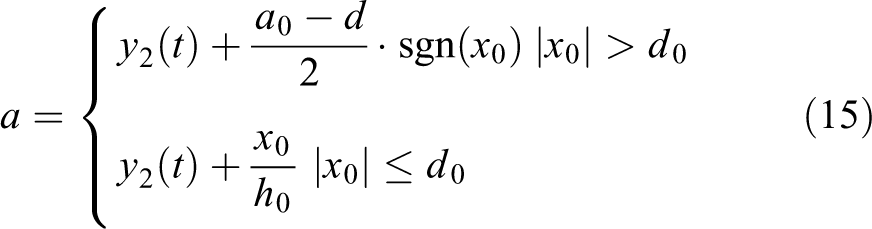
When the depth of the AUV is fixed at a certain position, the piston is in the equilibrium position, and the system is in the equilibrium state. Suppose that at a certain moment, the AUV is subjected to instantaneous disturbance and deviates from the position of fixed depth (the deviation depth is Δh). At this point, the piston system acts to deflect the piston from its equilibrium position Δl. Thus, the robot sinks and floats with the movement main force, namely, surplus buoyancy Δp. Owing to surplus buoyancy Δp generated by Δl, depth feedback and expectation deviation Δh are the input of the ADRC controller in the control system. The outputs are control quantity Δl, which is the input of the piston system, and control quantity h. Control quantity Δl is the offset of the piston, that is, the distance from the balance position. The direction of piston contraction is positive. Piston speed is directly related to motor speed. The specific control is shown in Figure 2.

ADRC control block diagram of sinking and floating systems. ADRC: active disturbance rejection control.
In the figure,
AUV motion is generally six degrees of freedom in space but can be decoupled into the plane motion of horizontal and vertical planes at low maneuverability. In this part, AUV vertical plane motion with six degrees of freedom and a brushless DC motor model are comprehensively described and designed.
Establishment of the AUV depth mathematical model
A mathematical description of AUV dynamics is crucial for robust control design. AUV modeling includes kinematics and dynamics. The following assumptions are established to derive the mathematical model of AUV vertical plane motion and decouple the AUV model of the object height coupler. The AUV is a rigid body. An underwater robot is adopted as the research object. Rudder angle coupling is disregarded. Viscous hydrodynamic force is expressed by a linear derivative under conditions of small spur and drift angles.
The motion and fixed coordinate systems in Figure 3 are established to describe the motion of the underwater robot comprehensively.

Earth- and body-fixed frames for AUV. AUV: autonomous underwater vehicle.
Establishing an accurate AUV dynamics model is important for AUV control. The representation of the mathematical model based on society of naval architects and marine engineers (SNAME) is presented in Table 1.
Mathematical model representation based on SNAME.

Assuming that the quality of the underwater robot is the center of m, the linear velocity of G is

where m is the quality of the underwater robot; xG
, yG
, and zG
are the barycenter coordinates of the AUV; Ix
, Iz
, and Iz
are the moments of inertia of mass m of the AUV on Ox
, Oy
, and Oz
axes, respectively; u, v, w, p, q, and r are the angular velocities of the six degrees of freedom;
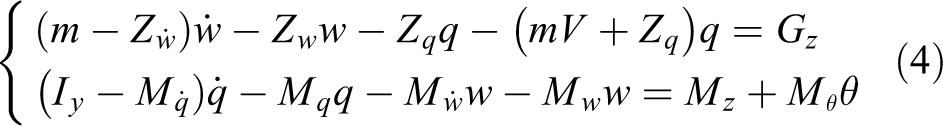
When the underwater vehicle is weakly maneuvering on the vertical plane and motion parameters u, w, and q are small, the vertical in-plane formula is

In formula (2), the expressions of X, Z, and M are
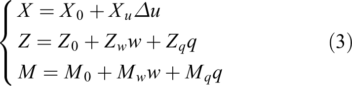
where X 0 is the resistance experienced by the AUV during navigation in a straight line; Xu , Zw , Mw , and Mq are the hydrodynamic coefficients of the AUV; and Z 0 and M 0 denote zero lift force and moment, respectively.
When
This formula is simplified into the depth change caused by the change in the water volume of the ballast tank and that in longitudinal inclination due to the water injection ratio of front and rear water tanks. The simplified results are as follows

where z is the depth function of time t,

Mathematical model of the motor and propeller
The following assumptions are made for the motor to simplify the analysis without losing generality of motor motion. The brush is on the geometric neutral line and has a quadrature axis armature reaction but no direct axis armature reaction. The brush is narrow, and the commutation is a straight line. The permanent magnet emits a constant flux without considering the demagnetization effect. Ignoring magnetic saturation, the superposition principle can be applied, that is, the magnetic permeability coefficient of the motor core part is constant.
With the simplification provided by these assumptions, the working principle of the propulsion motor can be obtained, as shown in Figure 4.

Diagram of the working principle of the underwater robot propulsion motor.
Armature current ia and speed Ω are state variables combined with the principle of underwater robot propulsion. According to the principle of Kirchhoff’s law and Newton motion, the formula of state is written as follows
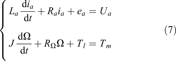
where ea
is the armature induction potential, Tm
is electromagnetic torque, Tl
is load torque, Ra
is armature resistance, La
is armature inductance,
According to the basic theory of permanent magnet DC motors

If the saturation effect is disregarded, then flux ϕ and the motion coefficient are constant

Substituting formula (8) into formula (7) yields
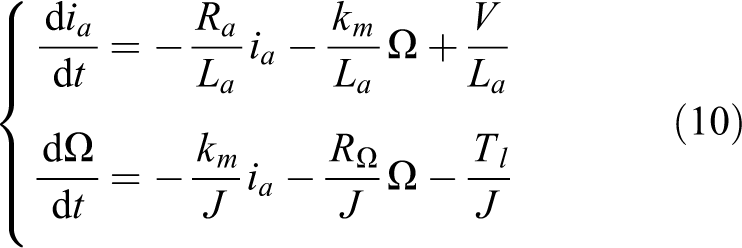
The mathematical model of the propulsion motor system of the underwater robot is as follows

The actual motor parameters are
AUVs have strong coupling and serious nonlinearity. Thus, dynamic response accuracy, robustness, and stability of variable depth control are difficult to meet. In practical engineering, environmental factors, such as current and temperature, change with the change in sea area and water depth. These interference factors are complex functions of time and space and are difficult to predict and model, resulting in strong interference and time-varying model parameters in AUV control.
Design of the improved ADRC controller
ADRC technology utilizes the advantages of nonlinearity to obtain stable, rapid, and robust controlled systems. It solves certain problems that linear control systems cannot. ADRC also regards uncertainties and disturbances, including internal and external ones, as total disturbances, which are different from the standard disturbances in system dynamics. In addition, ADRC estimates and eliminates total disturbances in real time through an extended observer. Therefore, ADRC reduces the disturbed, uncertain, and nonlinear controlled object to a convenient integral series type, thus converting the design of the control system from complex to simple and from abstract to intuitive. ADRC has three parts. The first one, TD, solves the contradiction between rapidity and overshoot in traditional control by using state feedback in the form of a synthesis function of nonlinear fastest control. The second part, ESO, uses the input and output of the controlled object to observe the internal state and external unknown disturbance of the controlled object. The last part, NSEF rate, provides high-quality control through a special nonlinear combination of the controlled object.
TD design
In the improved ADRC for underwater robot submarine ascent, TD is used as a filter and differential function. TD filters the output measurements of the controlled object to solve the contradiction between the fast response and overshoot of the system, and it can be used to arrange the transition process. TD exhibits the following advantages when adopted in feedback control for the transition process: (1) resolution of the contradiction between overshoot and rapidity; (2) enlarged selection range of error feedback gain and error differential feedback gain, which facilitates easy tuning of the system; and (3) increased range of object parameters adapted to the given feedback gain, resulting in easy tuning. The specific algorithm is as follows

where


The sinusoidal signal is selected as the input signal for simulation. Figure 5 shows the TD response curve.

TD response curve. TD: tracking differentiator.
Improved ESO design
ESO is the core of AUV based on the improved ADRC. It classifies all types of disturbances from the inside and outside of the AUV system as “total disturbances” of the system. Thereafter, ESO estimates the state and “total disturbances” of the underwater vehicle system in real time. Simultaneously, ESO compensates for perturbation and transforms the nonlinear and uncertain object with unknown perturbation into an integral series linear object. ESO is based only on the input and output information of the control object and does not depend on the specific mathematical model of generating disturbance. Thus, it has strong robustness.
The traditional nonlinear function is non-differentiable at the origin and piecewise point and has poor continuity and smoothness. This work transforms the
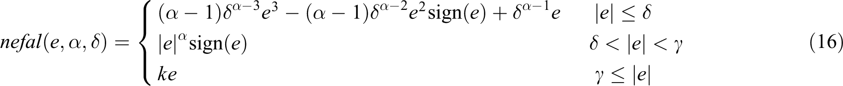
The algorithm expression of ESO is as follows

where e is the observation error, k is the gain of the feedback part, u is the control output, b is the compensation factor, δ is the filtering factor, Z
1 is the estimated value of x, Z
2 is the estimated value of

The solution is as follows

β 01 = 60, β 02 = 240, and β 03 = 890. The sinusoidal signal is selected as the input signal for simulation. Figure 6 shows the response curve of ESO.

ESO response curve. ESO: extended state observer.
Stability proof of ESO
ESO stability analysis is the core problem of the ADRC controller. Assuming that

The error formula can be transformed into the form

where

Evidently,

then obtaining a matrix D comprising positive numbers as the principal diagonal is possible, that is
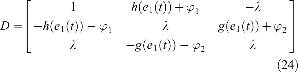
Positive definite symmetric moments of


The Lyapunov function of the error formula is assumed as follows:
At the local equilibrium point of the error system, the integrand value of the first term in
Improved NSEF design
NSEF combines the tracking and differential signals generated by TD and the state estimation errors of the object model generated by ESO through nonlinear functions. The initial control quantity is generated, and the compensatory control quantity compensated for by the real-time action of the estimated internal and external disturbances is considered. The final control quantity is obtained and inputted into the control object. NSEF can overcome steady-state, high-frequency oscillation and improve disturbance rejection performance. Furthermore, NSEF considerably enhances the dynamic characteristics of the closed-loop system. The algorithm is expressed as follows:
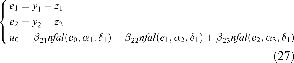
where e
1 is the error signal; e
2 is the integral of the error signal; and

NSEF response curve. NSEF: nonlinear state error feedback.
Structure of the improved ADRC
The reference acceleration feedforward is enhanced with the improved ADRC to implement high-precision trajectory tracking control of the AUV. The improved ADRC not only effectively improves the trajectory tracking accuracy but also increases the anti-interference capability. The control performance of ADRC is likewise considerably improved. The second-order nonlinear system can be converted into a “second-order pure integrator series system” according to the total disturbance estimation. When ideal trajectoryyr is known, the reference acceleration, that is, the second derivative of ideal trajectory yr , can be obtained. This value is assigned to intermediate control v 0. Therefore, controlled quantity y, that is, the actual displacement, can track ideal trajectory yr well. Figure 8 shows the specific structure.

Structural diagram of the improved ADRC for the AUV. ADRC: active disturbance rejection control; AUV: autonomous underwater vehicle.
Simulation and analysis of experimental results
Simulation results
An ADRC simulation model is established with Simulink in MATLAB to verify the performance of ADRC for AUV control. The performance of PID, traditional ADRC, and improved ADRC in underwater robot control is verified via simulation. The same simulation parameters are used for the traditional and improved ADRC so that performance can be evaluated under similar conditions. Table 2 shows the specific parameters.
ADRC parameters.

ADRC: active disturbance rejection control; TD: tracking differentiator; ESO: extended state observer; NSEF: nonlinear state error feedback.
Sea current is a frequently encountered disturbance by AUVs, and changes in sea current are gradual. In the simulation process, sea current is considered a stable and steady disturbance. Waves are another type of interference commonly encountered during AUV navigation. According to the stochastic process, waves can be treated as a random process. Thus, waves are regarded as random disturbances during the simulation. The performance of the AUV control system is simulated and verified under the following conditions.
First, a depth step response signal of 2.5 m is considered. Figure 9(a) and (b) shows the response curves of the system without sea waves and with step interference (30 and 60 s), respectively. Figure 9(c) shows the response curve of the system with random disturbances, such as waves and currents.
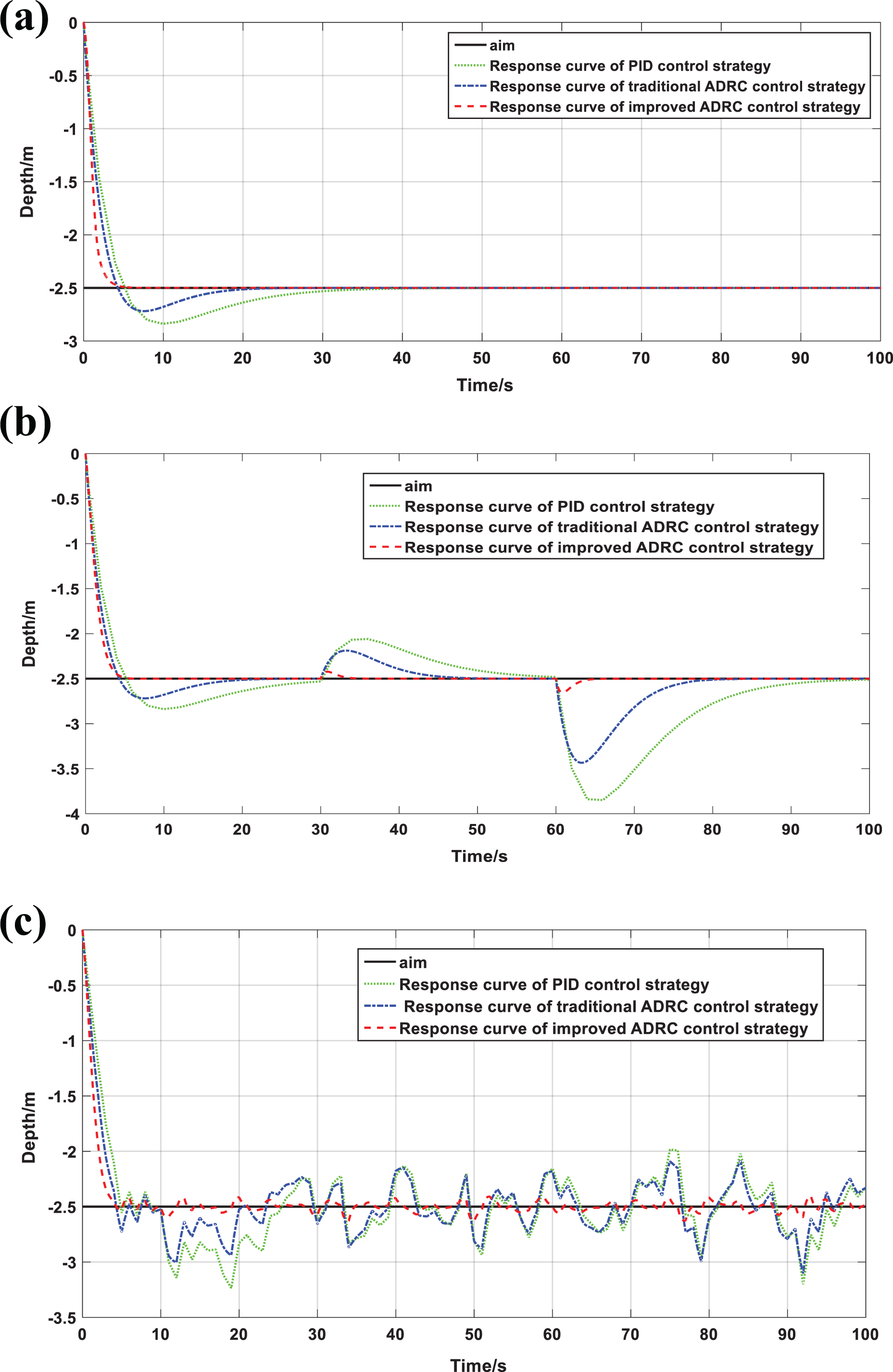
Response curves at 2.5 m depth: (a) Response curve of constant depth tracking without wave current interference; (b) response curve of interference in 30 and 60 s is tracked at fixed depth; and (c) response curve of wave current interference in constant depth tracking.
By comparing the depth–setting response curves of PID, traditional ADRC, and improved ADRC control, the control performance of the three control schemes can be obtained, as shown in Table 3. Figure 9(a) shows that the response time of the improved ADRC is 37.1 and 19.0 s shorter than those of PID and traditional ADRC control, respectively. The overshoot of the improved ADRC is 13.5% and 8.7% less than those of PID and traditional ADRC, respectively. The results in Figure 9(b) indicate that the response time of the improved ADRC is 22.2 and 15.9 s shorter than those of PID and traditional ADRC control, respectively. The overshoot of the improved ADRC is 10.5% and 5.5% less than those of PID and traditional ADRC, respectively. In the case of large disturbance, the response time of the improved ADRC is 29.9 and 18.8 s shorter than those of PID and traditional ADRC control, respectively. The overshoot of the improved ADRC is 47.3% and 30.8% less than those of PID and traditional ADRC, respectively. Evidently, the improved ADRC has a small overshoot and high recovery speed regardless of small or large disturbances. Figure 9(c) shows that the overshoot of the improved ADRC is 25.8% and 20.6% less than those of PID and traditional ADRC, respectively. The precision of the improved ADRC control is better than that of PID and traditional ADRC control.
Comparison of depth control performance.

ADRC: active disturbance rejection control; PID: proportional–integral–derivative.
Second, a square wave signal with variable depth is considered. Figure 10(a) and (b) shows the deepening response curves of the system without and with random disturbances, such as ocean waves and currents, respectively.
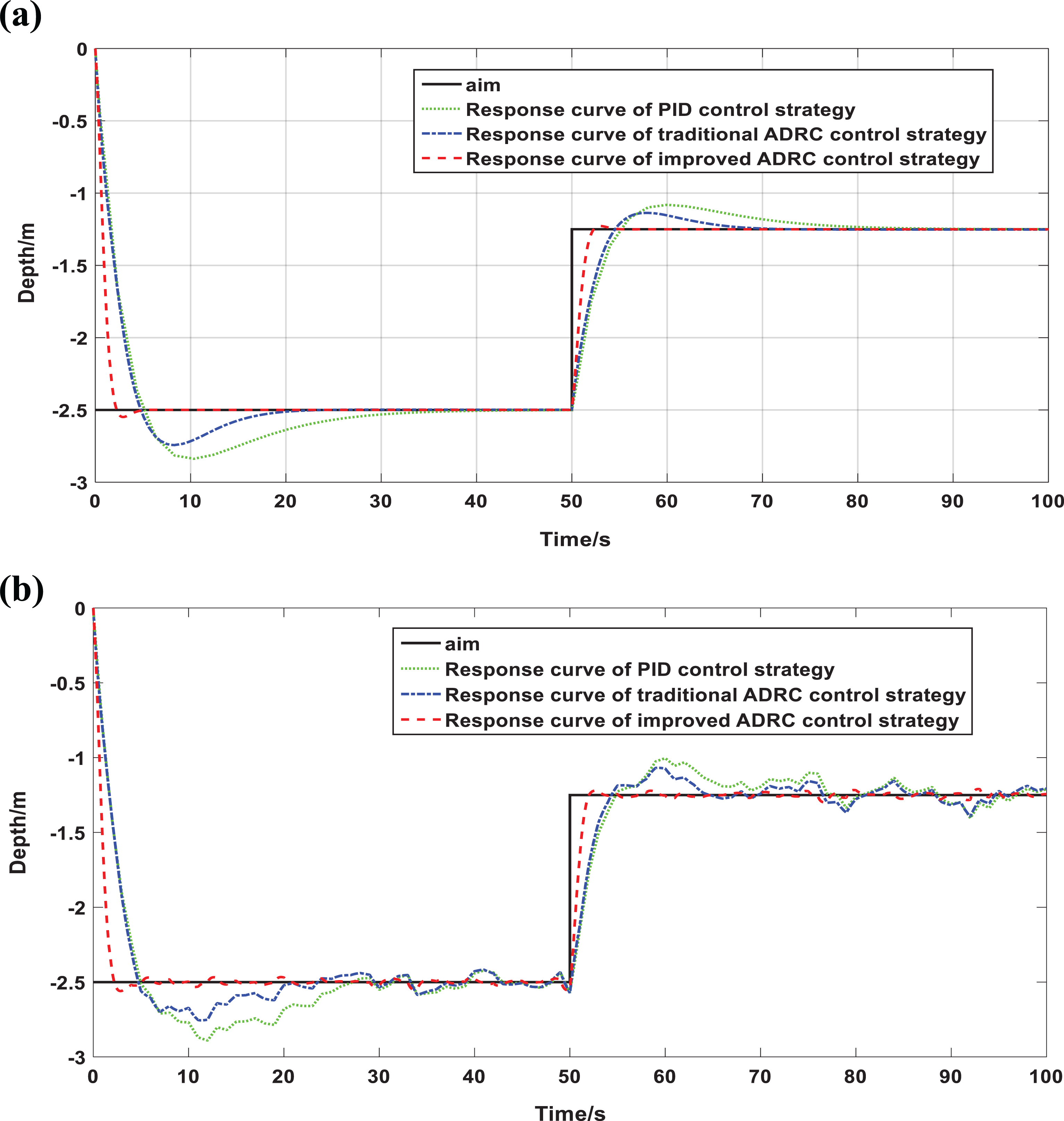
Response curves for variable depth tracking: (a) Response curve of variable depth tracking without wave current interference and (b) response curve of wave current interference in variable depth tracking.
The control performance of the three deepening control methods can be obtained by comparing the response curves of PID, traditional ADRC, and improved ADRC (Table 4). Figure 10(a) shows that the response time of the improved ADRC is 41.0 and 18.6 s shorter than those of PID and traditional ADRC, respectively. The overshoot of the improved ADRC is 7.4% and 3.9% less than those of PID and traditional ADRC, respectively. The results in Figure 10(b) show that the overshoot of the improved ADRC is 13.3% and 7.8% less than those of PID and traditional ADRC, respectively, even with the occurrence of random disturbances, such as waves and currents. The improved ADRC has a higher adjustment speed and smaller overshoot compared with PID and traditional ADRC.
Comparison of depth control performance.

ADRC: active disturbance rejection control; PID: proportional–integral–derivative.
Lastly, a sinusoidal tracking signal is considered. Figure 11(a) and (b) shows the response curve of the system sinusoidal tracking signal without and with disturbances, such as waves and currents, respectively.

Response curves for sinusoidal tracking: (a) Response curve of sinusoidal tracking without wave current interference and (b) response curve of sinusoidal tracking with wave current interference.
The control performance of the three tracking responses is obtained by comparing the sinusoidal tracking response curves of PID, traditional ADRC, and improved ADRC. The results in Figure 11(a) show that the tracking times of PID, ADRC, and improved ADRC to the first trough of wave 18.1, 16.5, and 16.1 s, respectively. The improved ADRC has an enhanced control effect and dynamic characteristics and can complete sinusoidal tracking according to the planned route. Figure 11(b) shows that the improved ADRC has smaller fluctuation and stronger anti-jamming ability than PID and traditional ADRC when the system is disturbed by random environment occurrences, such as sea waves and currents.
Comparison of Figures 10(a), 10(b), 11(a), and 11(b) verifies that the improved ADRC has a fast regulation time and a small overshoot. Figures 10(a) and 11(a) demonstrate that the improved ADRC has the fastest regulation time and the least overshoot time among the compared controllers. When the improved ADRC is subjected to external interference, it manifests strong robustness and high control accuracy. Figures 10(b) and 11(b) indicate that PID has the largest tracking fluctuation among the compared controllers. By contrast, improved ADRC exhibits only a slight fluctuation, and the tracking signal is stable. The simulation results show that the improved ADRC is robust, fast, and accurate.
Experimental result
The brushless DC motor is the AUV driver. A comparative analysis of AUVs controlled by the improved and traditional ADRC is performed to determine the propeller driving effect on the AUVs. Table 5 shows the motor parameters.
AUV driving motor parameters.

AUV: autonomous underwater vehicle.
Figures 12(a), 13(a), and 14(a) show the control curves of PID; Figures 12(b), 13(b), and 14(b) show the traditional ADRC control curves; and Figures 12(c), 13(c), and 14(c) show the improved ADRC control curves.
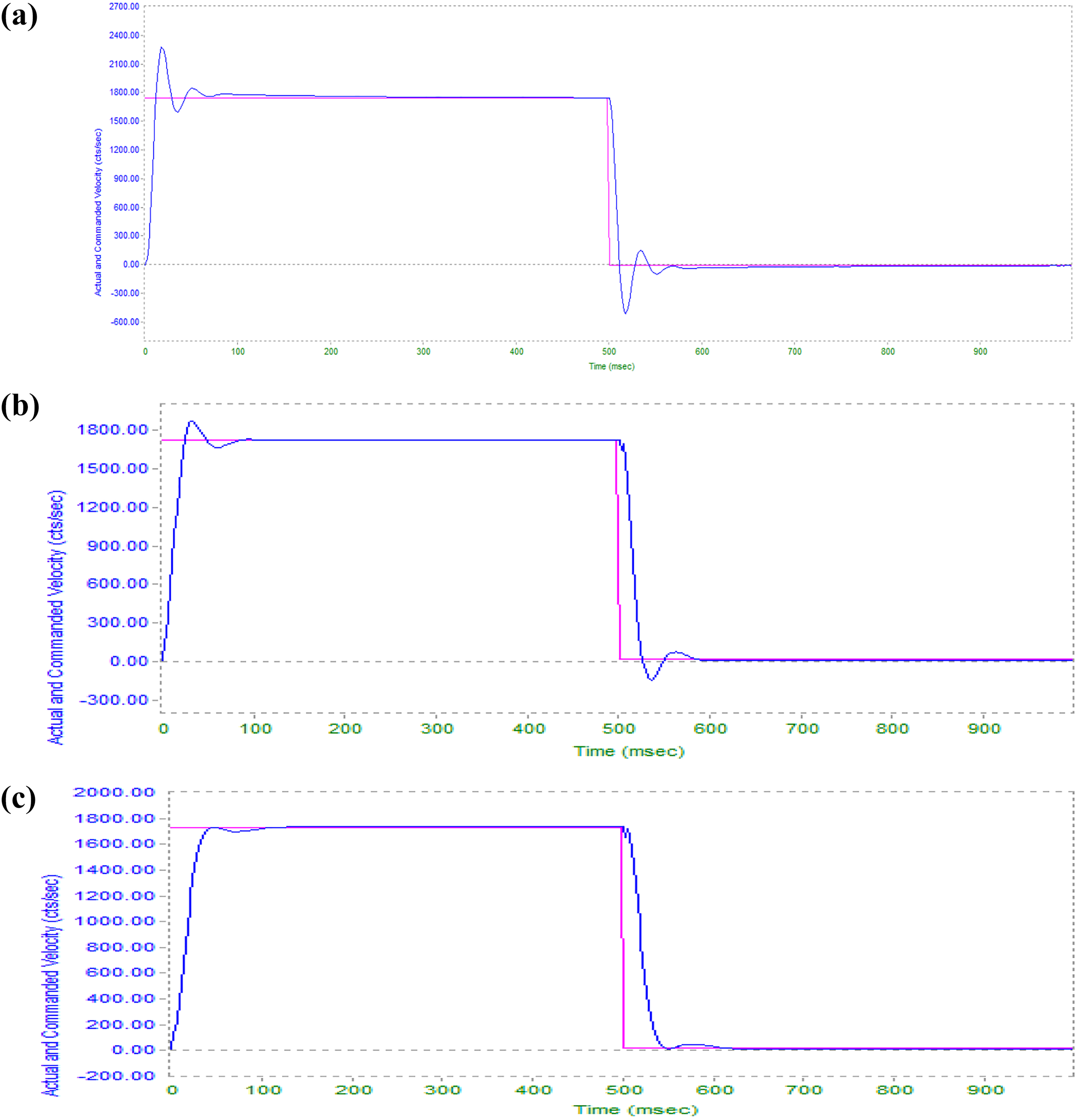
Response curves of 1760 r/min speed input. (a) PID, (b) traditional ADRC, and (c) improved ADRC. PID: proportional–integral–derivative; ADRC: active disturbance rejection control.

Response error curves of 1760 r/min speed input. (a) PID, (b) traditional ADRC, and (c) improved ADRC. PID: proportional–integral–derivative; ADRC: active disturbance rejection control.

Response curves of sine signal speed input with 1000 amplitude and 10 HZ frequency. (a) PID, (b) traditional ADRC, and (c) improved ADRC. PID: proportional–integral–derivative; ADRC: active disturbance rejection control.
Figure 12(a) to (c) presents the step position signals with a given signal position of 1760 r/min and response error curves of Figure 13(a) to (c). The improved ADRC has no overshoot and only needs approximately 0.1 s to stabilize at the target value. The traditional ADRC needs approximately 0.2 s to stabilize from the given signal and has 6% overshoot. By contrast, PID requires approximately 0.3 s to stabilize from the given signal, and the overshoot is 31%. In comparison with traditional ADRC and PID, the improved ADRC has smaller fluctuation and distortion of the tracking curve, better tracking of the input signal curve, and more stable speed control.
Figure 14(a) to (c) demonstrates that the amplitude and phase lag of the traditional ADRC are larger than those of the given ADRC when the input is sinusoidal, and the tracking error is larger. However, the PID response lags behind and cannot track the peak position. The response curve of the improved ADRC is basically the same as the input curve. No phase advance or phase lag and tracking error occur.
The comparison shows that the improved ADRC has better control precision and tracking performance than PID and traditional ADRC. This superiority is attributed to the fact that ESO based on the improved nonlinear function can accurately observe and compensate for the total disturbance of the system. The improved NSEF improves the quality of the input signal, and the added feedforward link effectively improves the trajectory tracking accuracy. Thus, the improved ADRC has enhanced adaptive ability, good tracking performance, and strong robustness and anti-interference ability.
Conclusion
An improved ADRC with high-precision trajectory tracking is proposed to solve the overshoot problem when an AUV is in deep motion. A mathematical model that includes AUV depth determination and a propeller model are established. An improved auto-disturbance rejection controller comprising TD, ESO, NSEF, and acceleration feedforward links is designed. The trajectory tracking accuracy of the system is improved by increasing the acceleration feedforward link. The improved ESO observes and compensates for the total disturbance of the system in real time and enhances the quality of the input signal through the improved NSEF. Therefore, the trajectory tracking accuracy and compensation capability for uncertain disturbances are effectively improved. High-precision trajectory tracking is also realized. The simulation and experimental results prove that the improved auto-disturbance controller has better adaptability and stronger robustness and anti-interference capability than PID and traditional ADRC control. Future research could focus on trajectory planning of the system and optimization of the dynamic performance of the controller. From the perspective of practical engineering application, the simulation and experimental results prove that the improved auto-disturbance controller has better adaptability and stronger robustness and anti-interference than traditional ADRC and PID controllers whether the underwater vehicle moves at a variable depth or is disturbed. However, this work has shortcomings due to the limitations in time and test environment. Future research could focus on the application of the improved ADRC in trajectory planning of AUV systems and improve the control effect and anti-jamming performance of the improved ADRC.
Footnotes
Declaration of conflicting interests
The author(s) declared no potential conflicts of interest with respect to the research, authorship, and/or publication of this article.
Funding
The author(s) disclosed receipt of the following financial support for the research, authorship, and/or publication of this article: This research is supported by the AnHui Natural Science Foundation (no. 1808085MF182). This research is supported by the AnHui Provincial Key Research and Development Plan Project- Special Scientific and Technological Cooperation with Foreign Countries (no. 1804b06020368).This research is supported by Anhui Provincial Natural Science Foundation (no. 1808085QE169).