
Abstract
In the wake of the continuous deepening of the application of new generation information technology in the manufacturing field, digital twin, as a most new active factors for smart manufacturing, has become a new research hot spot. Based on such a background, the article proposes a novel application framework of digital twin-driven product smart manufacturing system and analyzes its operation mechanism. Key enabling technologies such as digital twin mapping technology with manufacturing entity, twinning of cyber and physical manufacturing system, as well as twining data-driven machining parameter optimization are also illustrated in detail. Finally, a case of the aeroengine fan blade manufacturing is given to demonstrate the feasibility and effectiveness of the implementation method mentioned above. Meanwhile, potential industrial applications and limitations are discussed as well to provide valuable insights to aeroengine blade manufacturers.
Introduction
With the integration and expansion of physics, data science, and the new generation of information technology (e.g. Mobile Internet, Big Data, Artificial Intelligence, etc.), digital manufacturing technology dominated on smart manufacturing is brewing. 1,2 Moreover, due to the limitation of environmental and resource, smart manufacturing is the only way to improve the level of manufacturing industry. 3,4 Most of all, information exchange, and data convergence, between physical and information space continuously is the cornerstone. At present, there is a great shortage of real-time data interaction and convergence between virtual models and physical manufacture equipment to generate accurate information for smart product manufacturing system. 5 In this context, as a most potent tool to support future interaction with physical and virtual worlds, digital twin gradually comes into the public view. With the publish of industrial 4.0 and smart manufacturing strategies, digital twin as a new research field has gradually attracted wide and high attention by scholars and major industrial organization. In 2017, Gartner predicted the digital twin would be one of the top 10 strategic science and technologies for three consecutive years long. 6 In November 2017, the Lockheed Martin experts asserted digital twin would be the crucial technique in aerospace and defense industry from now on. Subsequently, the China Association of Science and Technology claimed digital twin is one of the 10 significant advances in science and technology field. Digital twin is the digital description of physical entities, which can monitor and control physical entities in real-time and all-round way. And it is increasingly welcomed as a crucial technology to accomplish the goal of cyber–physical system (CPS) and a core technology of achieving smart manufacturing. 7
According to the motivations discussed above, the rest of this article is organized as follows: first of all, on this basis of the literature review about digital twin in the second section. The third section presents a novel application framework of digital twin-driven product smart manufacturing system (DT-PMS) and key enabling technologies. An application case of the aeroengine fan blade manufacturing is given to verify the proposed implementation methods in the fourth section. The last section is a conclusion of the article, which lists the main contributions and future research work.
Related work
Development of digital twin technology
From the angle of historical time, the development of digital twin is shown in Figure 1. The idea of digital twin can stem back to the Apollo project of NASA in 1969. 8 Professor Grieves firstly put forward the definite definition of digital twin in 2003, which was only a virtual representation of a physical product at that time. 9 Until 2012, a road map called “Modeling, Simulation, Information technology, and Processing” was published by NASA, 10 which provided a series of new perspectives for the concept’s evolution. Meanwhile, digital twin includes mainly the physical models in physical space, the three-dimensional (3-D) virtual models in virtual space and the data that bridges the two spaces, 11 which is widely now accepted.
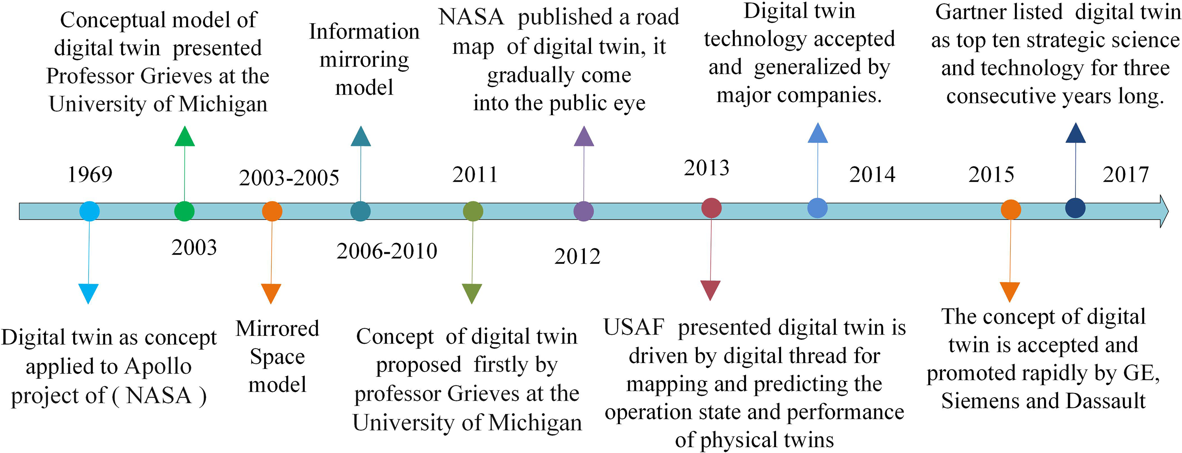
Development of digital twin.
Along with the development of digital twin technology, the US Air Force presented the concept of digital thread in 2013. It is build based on modeling and simulation tools. And it is also data flow and information flow throughout the product life cycle, from product design, process, manufacturing to utilization, and maintenance. 12 Digital twin is an integrated multi-physics, multi-scale, probabilistic simulation model of a complex product and is driven by digital thread for mapping and predicting the operation state and performance of physical twins throughout their life cycle by the aid of the high-precision model, sensor information, and input data. 13 Thus, it can be easily seen that digital twin is object, model, and data, while digital thread is method, interface, and enabling factors. Nowadays, digital twin is integrated into internet of things (IoT), it will be able to provide more specific services to the product life cycle. In the process of product manufacturing, it is quite necessary for decision makers to make a global manufacturing planning by digital twin and digital thread to achieve collaboration between designers and manufacturers. Due to different motives of designers and manufacturers, there is usually insufficient data integration, feedback, and traceable in the product manufacturing system. Therefore, digital thread will also be applied to integrate digital twin models in manufacturing life cycle in the article.
Applications of digital twin for product smart manufacturing
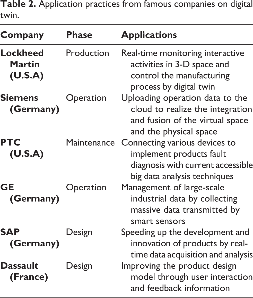
Digital twin technology duplicates product and production system in cyberspace and makes their digital models and physical models interact and dynamic response in real time. 14,15 It provides a powerful guarantee for the product smart manufacturing and further accelerates the integration of production with IoT. From the perspective of product smart manufacturing, digital twin can be divided into unit level (e.g. equipment-level), system level (e.g. manufacturing system), and system of system level (e.g. shop floor-level), 16 which is a systematic point of view about the applications of digital twin. The applications of digital twin for product smart manufacturing from different level are listed in Table 1. As for equipment-level, Zhao et al. 17 established digital twin-driven CPS to study autonomously controlling method of punching machine tool. Tao et al. 18 and Wang et al. 19 focus on fault diagnosis, prognostics, and health management for smart equipment. Luo et al. 20 discussed modeling and autonomous strategy of Computer numerical control (CNC) machine tool digital twin technology. In the aspect of manufacturing system level, Zhang et al. 21 proposed a digital twin-based application framework to provide engineering analysis capabilities and to implement rapid individualized designing and optimization of the glass production line. Karanjkar et al. 22 implemented energy optimization in an Surface Mounted Technology-Printed Circuit Board (SMT-PCB) assembly line using IoT and digital twin technology. Liu et al. 23 presented a digital twin-driven methodology for rapid design of manufacturing systems. Leng et al. 24 presented a digital twin-driven manufacturing system for parallel controlling of smart workshop and addressed proactive decision-making for the organization and operation of manufacturing resource. In the system of system level, Tao and Zhang 5 also proposed concept of digital twin shop floor and summarized its composition, operational mode, and key technologies. To improve the manufacturing efficiency and flexibility, Ding et al. 25 built the interconnection and interoperability of a physical shop floor and corresponding virtual shop floor by means of CPS and digital Twin technology. Zhuang et al. 26 proposed digital twin-based smart production management and control framework in a satellite assembly shop floor. Coronado et al. 27 performed part data integration, production control and optimization in shop floor digital twin. For the factory, Guo et al. 28 focused on the factory design to help the designer to escape design flaws based on flexible digital twin. Also, many famous enterprises, manufacturers, and software manufacturers also have put forward their business application of digital twin in life cycle management. Specifically, the applications practice in the major company on digital twin are listed and described in Table 2.
Application of digital twin for product smart manufacturing.

Application practices from famous companies on digital twin.
According to the research and practice applications presented above, it can be concluded that digital twin is a powerful tool and has extensive application prospect in the production practices. Digital twin also can play a fundamental role in advanced manufacturing environments toward Industry 4.0. Besides, once digital twin is fully integrated, it will be the next level of simulation. 29 However, from what has been discussed above, we may see that their emphasis of the above research is production process optimization and fault diagnosis, prognostics, modeling of smart equipment such as energy optimization, data perception, and improvement of product manufacturing process. There is a few literatures concentrating on the product manufacturing. Therefore this article attempts to propose the application framework and implementation key technologies of DT-PMS, and especially for complex mechanical parts manufacturing.
Application framework of DT-PMS and key enabling technologies
Based on the concept of digital twin and digital twin floor shop, 5,30 this section proposes an innovative application framework of DT-PMS and illustrates in detail key enabling technologies.
Application framework of DT-PMS
The open application framework of DT-PMS is proposed as shown in Figure 2, and the framework mainly consists of the following contents: system layer, information processing layer, physical layer, and model layer, and it mainly includes the following contents.

Application framework of DT-PMS. DT-PMS: digital twin-driven product smart manufacturing system.
Physical layer
The physical layer is a complicated, diversified, and dynamic manufacturing environment in physical space. It refers to physical entities sets existing objectively, which mainly includes manufacturing equipment and data acquisition apparatus. Manufacturing machines cover a series of entities, such as the physical machine tool, cutting tool, workpiece, and testing device. They are responsible for providing physical manufacturing data, receiving manufacturing tasks, and executing production activities to manufacture finished parts. All kinds of devices are isolated and distributed at first and they need to be interconnected, and manufacturing data need to be collected, integrated, and optimized before production. Therefore, it is necessary to build a manufacturing IoT network to realize real-time perception and interconnection of manufacturing resources by network module and perception module, achieving the iterative optimization for the parts manufacturing process by interacting with model layer.
Model layer
The product manufacturing model layer is the real mapping of product manufacturing in cyberspace, including mainly product digital twin model, machine digital twin model, process digital twin model, and so on. All the models are built by an emerging model-based definition (MBD) technology. The important is that the model layer has the attributes of interaction, computing, and control. 31 After adopting 3-D lightweight technology, various digital twin models are interrelated and collaborative, and manufacturing activities in physical space (e.g. product machining, quality testing) can be simulated and analyzed effectively in cyberspace. Furthermore, model layer provides control instructions for physical layer and optimization strategies to manufacturing service platform by machining database and knowledge database of information layer. In this way, digital twin model is predicted, iterated, and optimized continuously and becomes more accurate in manufacturing process, which makes itself more intelligent.
Information processing layer
The information layer is the information management platform for product manufacturing, including mainly digital twin data (DTD), manufacturing service information, and product service information. This layer is the key to realize the integration and interconnection of physical layer and model layer. Manufacturing data of physical layer, the experience of operators (such as operating method of a key process), and all kinds of data, models, knowledge, and rules of the model layer will be transmitted to information layer and stored in the corresponding database, model base, rule base, and knowledge base. In the process of product smart manufacturing, multisource and heterogeneous data mainly involve data from physical layer (e.g. machining operation data and online testing data), data from model layer (e.g. digital twin models data, simulation data predict data, and optimization data), data from system layer (e.g. designing scheme, resource distribution), and the fused data of them by information processing. In the center of this layer, as a bridge between physical resource layer and virtual model layer, DTD is made up of three elements and described as follows

where RPD represents perception data in physical space, VSD refers to virtual simulation data in the model layer, and FD is the fusion data between them. Real-time data and off-line data of product manufacturing are analyzed and mined using data fusion algorithms, converting them into FD, forming DTD. The symbol “⋈” is represented as a natural connection between them, indicating autonomous interaction between them. It is important to note that RPD, VSD, and FD are dynamic and updated constantly.
And DTD can be directly invoked to simulate and optimize production activities after encapsulation, providing the driving force for DT-PMS. It makes the whole manufacturing system aware of their states as well as the overall manufacturing task. For model layer, manufacturing data models are constructed and updated from DTD. For some special requirements, it provides manufacturing service platform of system layer the corresponding data, algorithms, models, and so on. Not only data of DTD make themselves update and expand, but also DT-PMS can be attained evolution and perfection regularly. Meanwhile, data sharing mechanism of information layer can eliminate communication barriers between information systems at all levels of the manufacturing system.
System layer
System layer composed of manufacturing service platform system and digital twin application subsystem. Manufacturing service platform is the set of service system, and it encapsulates the functions of MSS, such as ERP, MES, PDM, and MBD models, into the service platform, offering production services for the parts manufacturing. Digital twin application contains manufacturing service and product service application. Product service is an important component of manufacturing service, which can find and feedback the problems existing in manufacturing process, in turn improving product manufacturing service capability. 16 By virtue of data, models, rules, algorithmic, and knowledge of product and manufacturing service information in the information layer, system layer controls the operation of physical layer and model layer. The specific functions include product demand forecasting, product design, manufacturing precision prediction, machining progress, process optimization, product quality testing, and so on.
To achieve product smart manufacturing, the application framework not only embodies the integration of IoT, Big Data, and Artificial Intelligence, but also full-mapping and iterative optimization of DT-PMS are realized under the driving of DTD in the process of product manufacturing.
Digital twin mapping technology with product manufacturing entity
The idea of “digital thread” can date back to the production application of Lockheed Martin company. In the production process of F-35, they directly input MBD data into CNC machine tools to machining parts, which is named the new manufacturing mode as digital thread. Useful information of MBD can be read directly by CNC machine tools, robots, and testing equipment. At present Teamcenter® software of Siemens company (German) is a modern, adaptable product life cycle management (PLM) system using a digital thread for manufacturing process innovation.
32
It is collaborative software, which creates a digital thread of information for product life cycle.
33,34
In Figure 3, a novel operation mode of the closed-loop digital twin for product manufacturing is introduced by integrating digital twin and digital thread on the software platform throughout the whole life cycle of product manufacturing including design, simulation, manufacturing, and quality testing. The implementation steps of establishing the mapping relationship with manufacturing entity and digital twin model is described as follows: The first step is constructing digital twin model, it consists of building simulation model, design model, process model, and quality inspection model. The production flow of remote control and operation is achieved by digital thread, and all data models of product manufacturing system can share seamlessly and interactively with product manufacturing system and quality inspection system in physical space. The second step is to integrate digital twin model throughout the whole life cycle by digital thread, realizing seamless integration and synchronization with embedded CPS. In this way, we can see the real situation of physical equipment on the remote manufacturing service platform. The last step is to generate digital twin system of product smart manufacturing based on simulation and optimization of digital twin models, forming a smart closed-loop feedback from product design to manufacturing and quality inspection.
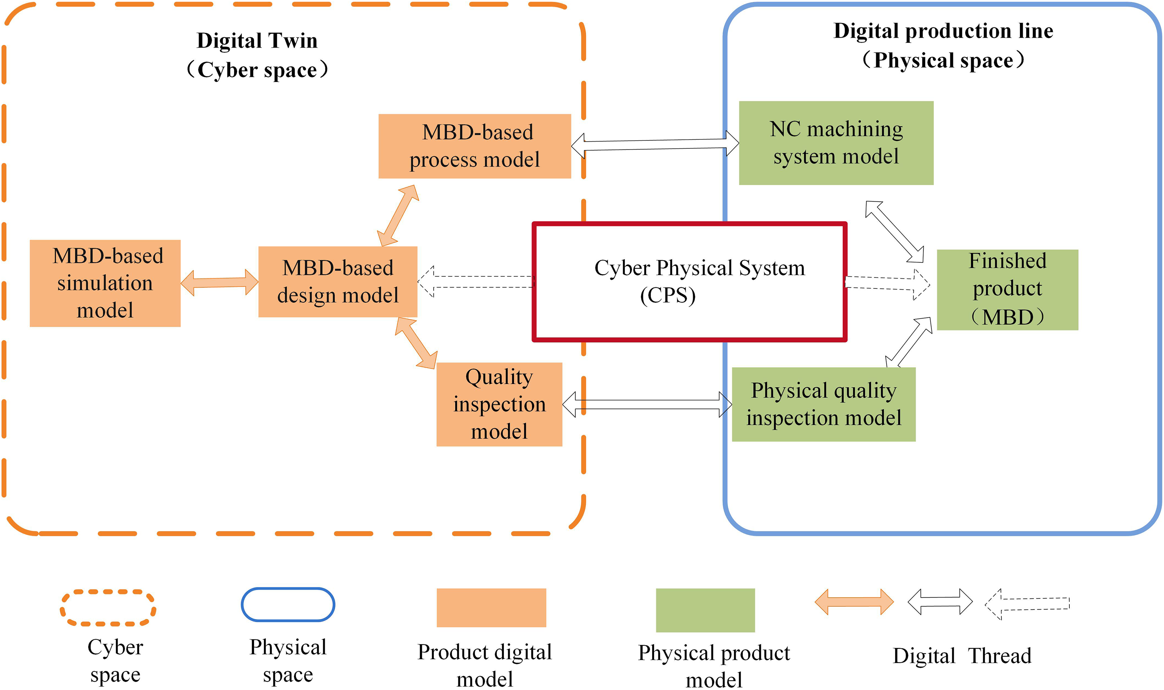
Mapping diagram between digital twin models and manufacturing entity.
The above implementation process will be discussed in detail by application cases in the “A application case of aeroengine fan blade manufacturing” section.
Twining of cyber and physical manufacturing system
The DT-PMS is resulted from the twinning between the physical manufacturing system and a virtual machine tool model, which is the mapping of real machine tools in cyberspace. Before product manufacturing in physical space, performance and parts machining of the real machine tool are not only simulated beforehand but also replaced physical prototypes for tool path simulation, collision interference, overcut check, and so on. With wide application of digital twin technology, CNC system suppliers and machine tool manufacturers have provided smart control software system corresponding to the hardware of numerical control (NC) system, respectively. Virtual NC controller kernel (VNCK) of Siemens integrated simulation and verification of CAM system and CNC system. Real NC code is verified on the cyber model as in real machining environment including prediction of processing quality, and then applied directly on the real machine tool. The virtual twinning of machining tool consists of geometric model, kinematic model, controller model, behavioral model, and human machine interface (HMI), as is shown in Figure 4. In which the HMI connecting with virtual machine controller is the virtual equivalent of real machine control panel, and the basic parameters of machine tool can be set in the HMI (see Figure 5). The virtual machine tool is operated and simulated in the state of mapping operating state of the actual machine and dynamic interaction, 35 forming the twinning of machine tool (on the model level). Because it is applied in practice as same as NC and programmable logic controller (PLC) used in real machine tools, it can simulate the machining process exactly the same as real machine tools, detect collision and interference, finding out programming errors, and optimizing cutting parameters to ensure processing efficiency and quality.
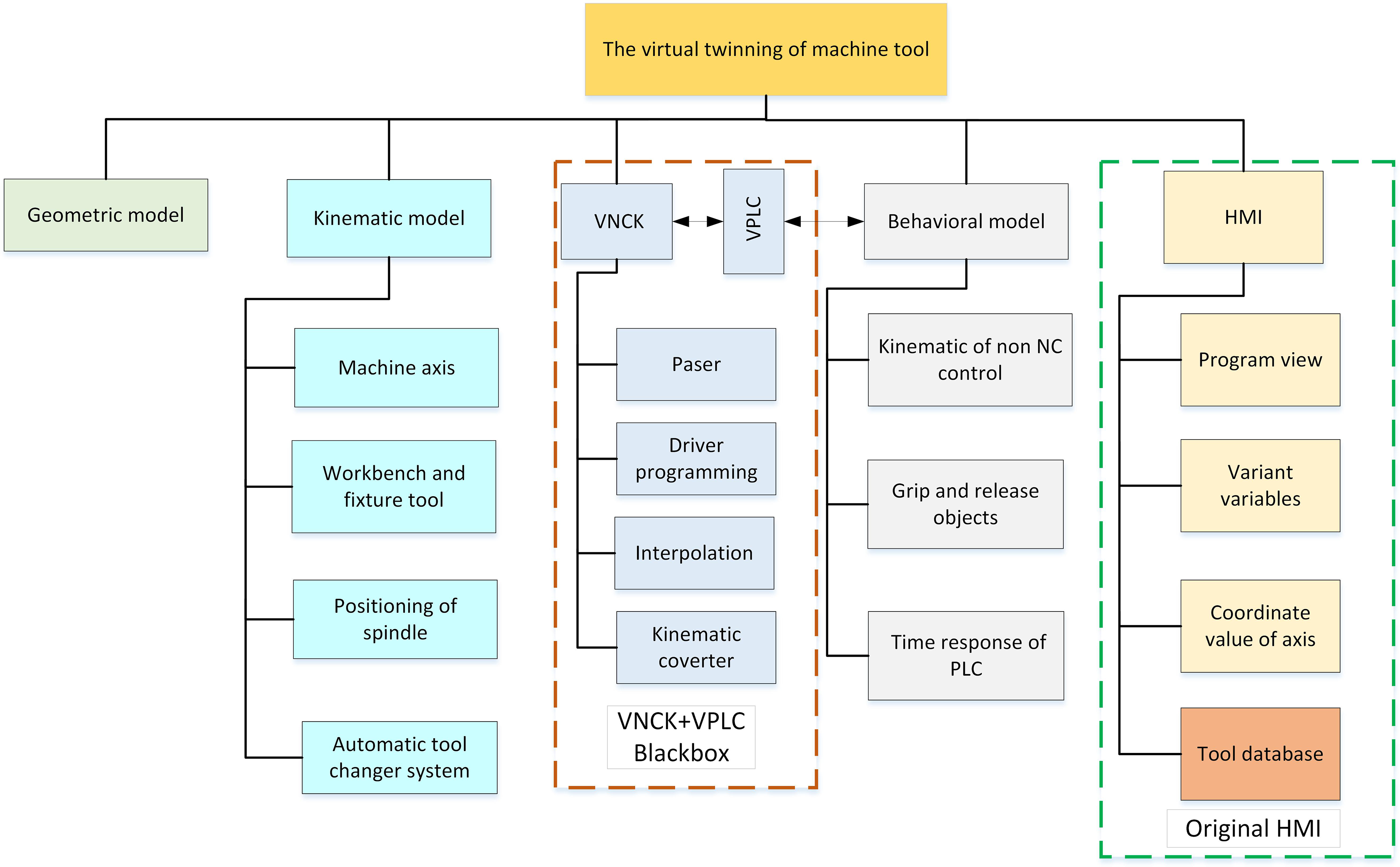
The architecture of machine tool virtual twinning. 35

Basic parameters of virtual machine tool in the HMI. HMI: human machine interface.
From the design of workpiece to manufacturing process, the twinning of manufacturing system can also collect the processing information and feedback these information back to the manufacturing execution system to form a closed-loop manufacturing system by integration of IoT and twinning of machine tool. In this way, any product problems or adjustments can be updated synchronously with production, and the manufacturing system becomes an intelligent, self-optimizing, autonomous production system by integrating intelligent algorithm, which will construct a really smart machining environment. 36
Twinning data-driven machining parameter optimization service
Traditional machining parameters mainly depend on experience data of production, and it is very difficult to optimize cutting parameters and to make full use of CNC machining performance in the process of machining complex parts. It has a great impact on the quality and efficiency of parts processing.
Moreover, with the increasing variety of need for industrial product service system, product manufacturing system cannot be solved by single-objective optimization but is often multi-objective optimization problems (MOP). 37,38 There may be mutually conflicting relations among multiple objectives, one of the solutions is the optimization solution for one objective, but is perhaps inferior solution for another. Therefore, the goal of MOP is to search a set of solutions which can make the multi-objective functions better trade-off with each other, achieving relatively satisfactory solution. Generally speaking, these solutions are called nondominant solutions, or Pareto optimal set. The MOP consist of multiple objective functions with inequality constraints and equality constraints, its mathematical model can be defined as follows:
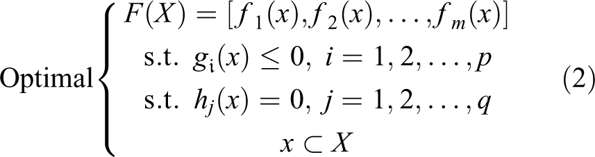
where
The goal of optimizing machining parameter is to improve the machining quality, production efficiency, and so on, realizing a dynamic responding to requirement of product service, which will be verified in the DT-PMS context.
A application case of aeroengine fan blade manufacturing
Project background
The fan blade is an important component of aeroengine, and its manufacturing level will directly affect the performance of the engine in harsh and extreme work environments. 41 The structure of turbine aeroengine and its fan blade is shown in Figure 6. With characteristics of free-form, thin-wall, titanium alloy material and twist of the blade surface, the blade manufacturing is always a serious bottleneck problem in the aeroengine industry field. For aeroengine, the fan blade machining (FBM) can take more than a third of time. 42 It is particularly important and urgent for aeroengine manufacturers to improve the machining quality and processing efficiency by smart manufacturing mode. At present, the blade manufacturing methods mainly include electrolytic machining, milling machining, precision forging, and so on. NC milling is widely used for its high machining accuracy, stable cutting, and high process maturity. However, blade NC machining process is not always in the ideal state even if adopting advanced simulation and NC programming technology. 43 What is more serious is that once choosing unreasonable machining parameters, it would reduce the service life of machine tools and cutting tools severely.

The structure of (a) aeroengine and (b) its fan blade.
With the rapid development of aeroengine industry, some major manufacturers have more and more demands on machining accuracy of fan blade. Therefore, fan blade manufacturing needs dynamic response to meet the personalized manufacturing service demand. But in reality, there are still some insufficiency in process planning and control for the blade manufacturing: (1) deficiency of closed-loop manufacturing data feedback and data convergence between physical space and cyberspace and (2) absence of unified product model for data transmission and sharing throughout manufacture life cycle. To resolve these challenges, this section takes the aeroengine fan blade as a case to validate the effectiveness of the proposed approach. Figure 7 depicts the detail implementation process and information interaction mechanism for digital twin-driven fan blade smart manufacturing, which includes mainly the construction phrase and the manufacturing phrase.

Implementation process of digital twin-driven fan blade smart manufacturing.
Construction phrase
The construction phrase mainly includes two parts: one is the development of a demonstrative prototype machine system in physical space, and another is the construction of fan blade manufacturing system digital twin model.
Construction of prototype machine system in physical space
The experimentation of a demonstrative prototype machine tool is undertaken in our university lab. The four-axis machining center is equipped with Sinumerik840D CNC system of Siemens, it is a top grade and strong openness NC system and can execute turning and milling task of various complex parts. In the integrating CNC system, the hardware is primarily made up of HMI for displaying feedback data programming and operating, numerical control unit and PLC embedded interfaces for communication and data transmission, servo drive unit, and so on. The experimental prototype is shown in Figure 8, and its detailed hardware configuration are listed in Table 3.
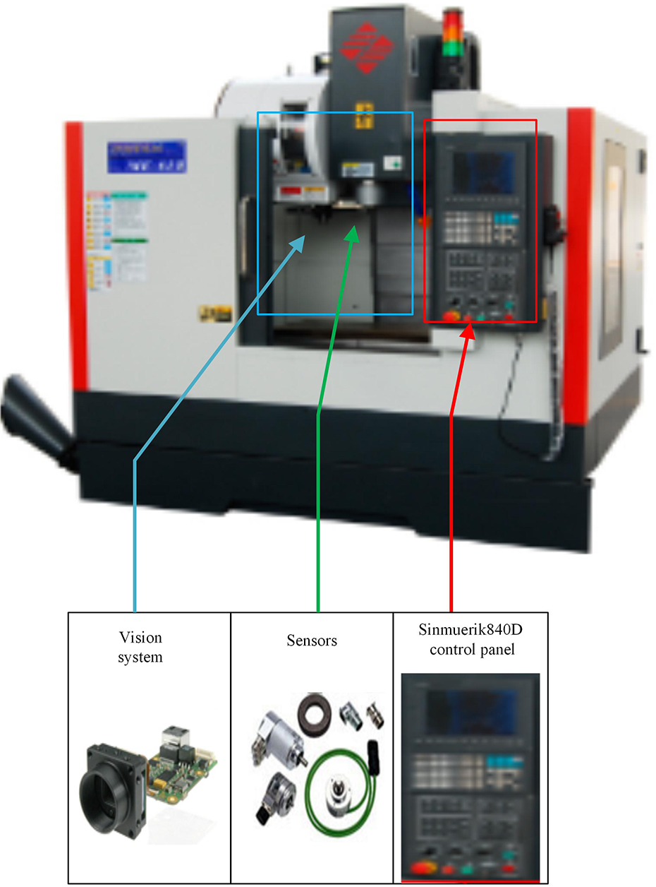
Experimental prototype of Siemens 840D CNC systems.
The hardware configuration of experimental prototype.

TCU: transmission control unit; MCP: machine control panel; NCU: numerical control unit; PLC: programmable logic controller.
To acquire real-time data and parameter of the operation status from the CNC machine tool, the Kistler, (Switzerland) 9017C type of force sensor is selected and mounted under the tool head, 8762A10 type of accelerometer sensor, and piezoceramic acoustic emission sensor 8762A10 (50–400 kHz) are fixed on the tool head. And the auxiliary sensor including13.56 MHz radio-frequency identification (RFID) tags are clung to workpieces and cutting tools. Therefore, a VNCK-driven machining loop is formed by data acquisition devices and controller, as is shown in Figure 9. In this loop manufacturing environment, multisource and heterogeneous manufacturing data generated from physical space is processed effectively and transmitted to the cyberspace via the user interfaces. Synchronously, machining orders can be retransferred from the cyberspace to the physical space. For example, the RFID technology is used to trace and locate the blades with quality problem, analyze the causes of the faults, generate feasible solutions, and the final results are fed back into the fan blade physical manufacturing system. According to the manufacturing networking system, the computing, service platform resources, data resources, and communication protocols are connected to the physical machining devices, realizing the goal of CPS for blade smart manufacturing.
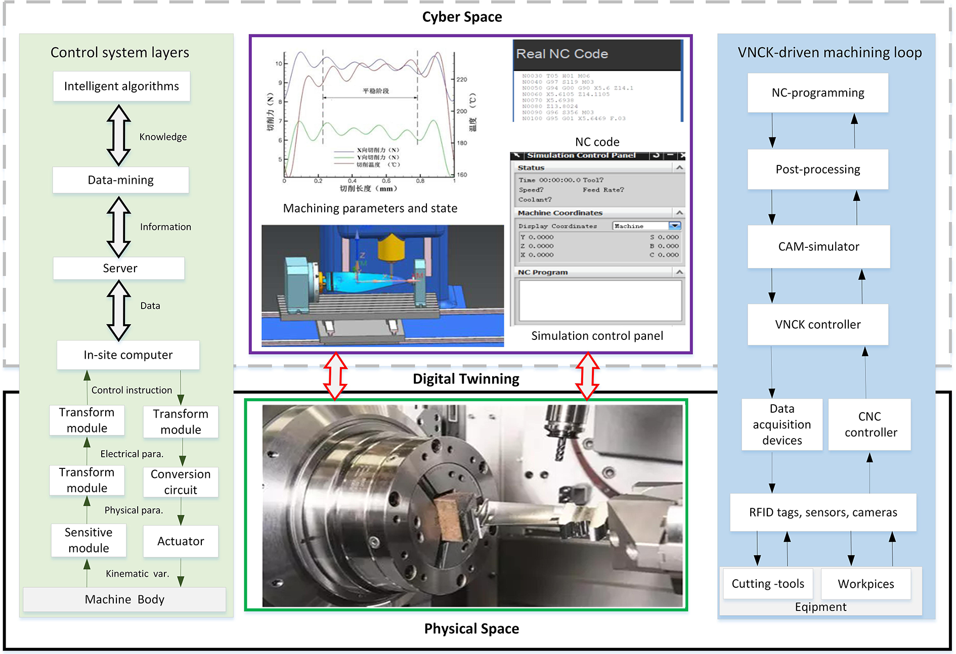
Digital twin-driven fan blade manufacturing in prototype machine system.
Construction of fan blade manufacturing system digital twin model in cyberspace
Likewise, a smart processing environment is also the precondition and guarantee for realizing the blade smart manufacturing in cyberspace, and it includes the creation of machining operation template set, resource library, knowledge library, and many processing files. The machining template set consists of 3-D coordinate systems, program groups, operation types, machine tools, fixtures, and other manufacturing resources. Users can also customize and call them by knowledge reasoning technology, increasing intellectualization of manufacturing. Once fan bade manufacturing plan is released to the design department, the designers can define the 3-D entity model of the fan blade following the modeling standards of aeronautical industry. And they specify the manufacturing information by MBD technology and achieve a virtual 3-D model with NX CAM system in UG software environment, as shown on model Ⅰ in Figure 12. It includes geometric dimensions, tolerances, and the technical requirements, and it is also the foundation of subsequent blade smart manufacturing. Meanwhile, a corresponding 3-D model of the test vertical milling machine has also been built by 3-D lightweight model technology. The four-axis CNC vertical milling machine 3-D model was built as much as simple to speed up to simulate the FBM. By transferring these models into the PTR format and assembling them, virtual manufacturing system with CNC vertical milling machine and the blade clamped on the working table is formed.
Manufacturing phrase
Manufacturing process simulation
In this step, the fan blade parameters of the 3-D design model are transferred to process engineers of the manufacturing department by the digital thread in Teamcenter software (version Teamcenter 9.1) environment. Based on the process template, process engineers create 3-D process sequences by calling manufacturing resources (such as a cutting tool, machine tool, and fixtures) on the design model to generate the blade process model readily, as is shown in the model Ⅱ in Figure 12. It also can simulate the real-time machining status by accessing manufacturing data.
Before the actual blade machining, the created process model is sent to the NC code program department. In the NX software environment, programmers and engineers load process resources (i.e. machines, tools, and fixtures) on the 3-D design model to create the blade process information model for each feature based on FBM technology. 44 Next, MBD-based simulation model of the FBM is as shown in model Ⅶ. Figure 10 illustrates the real-time online simulation of aeroengine FBM on the HMI, showing 3-D material removing process animation. Based on the simulation results, we can revise the machining scheme with the machining parameters optimized, achieving the satisfactory machining objectives.
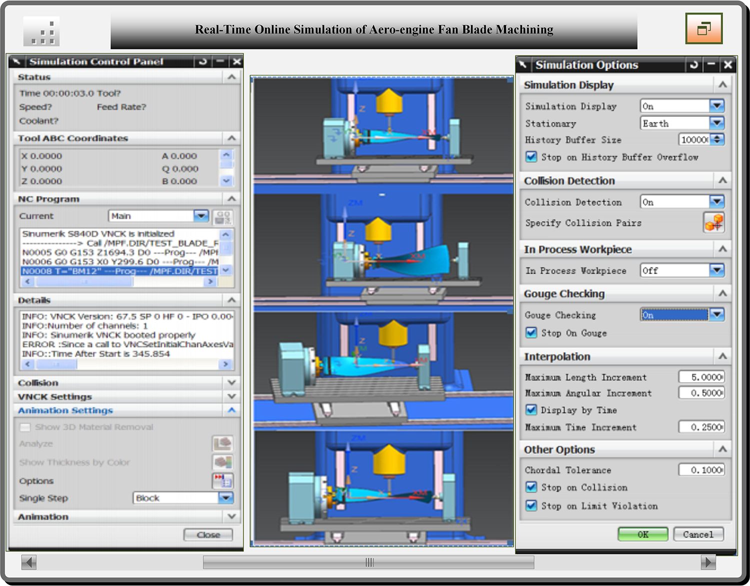
Real-time online simulation of aeroengine fan blade machining.
Quality inspection simulation
The quality inspection task is transmitted to the quality test department, the quality control engineers create the quality inspection model by loading the virtual inspection module, probes, and other resources on the 3-D design model using UG software (version UG8.5). The inspection module of the software can automatically generate the predefined measurement path. The online fan blade inspection simulation is shown in the model Ⅳ in Figure 12. Once meeting the quality requirements, it will be applied in the practical machining process.
Fan blade smart machining in physical space
Raw materials, CNC machine tool, cutting tools, and fixtures are allocated, and machining instructions are released to physical machine tool according to the production plan. And the verified process design model and its NC code are input into CNC machine tool to be used for manufacturing in physical space. The FBM model in the physical vertical milling machine is as shown in the model Ⅲ in Figure 12. During the machining phase, the physical CNC machine has been collecting parts machining information ceaselessly from sensors deployed on itself. And CNC machine and the blade digital twin model also get these data to update their status and generate real-time order to control the machining process or adjust the machining plan to ensure the consistency between the two sides. When the manufacturing process is finalized, the finished fan blade is manufactured, as is shown in the model Ⅳ.
Fan blade quality inspection in physical space
Next, the quality inspection task is transferred to the quality inspection department on site. The coordinate values of fan blades can be measured accurately using RENISHAW MP10 probe, (England), the physical blade quality measuring model is as shown in the model Ⅴ. The inspection results may also feed back into the canonical virtual quality inspection model by the embedded CPS, and at last return to the simulation model for the next simulation verification.
System performance evaluation
Traditionally, fan blade milling is prone to deformation and take a substantial amount of machining time, which affects the machining accuracy and efficiency. Therefore, it is of great significance to control machining deformation and production efficiency in a reasonable range. Maximum machining deformation and machining time are regarded as two main optimization objectives in the article, which is to enable the maximum processing deformation least and amount of machining time minimum, respectively. The optimization variables mainly include milling speed V s, feed amount per tooth z, milling depth C P, and milling width a 1. In addition, constraints mainly include the power of milling machine, workpiece machining quality, cutting tool conditions, and so on. The blade machining parameters optimization is an effective approach to resolve the conflicting between high machining efficiency and machining precision. 45,46 Figure 11 indicates the specific implementation process. The machining parameters optimization integrates the intelligent algorithm and machining database, and the optimization scheme ultimately is applied to the blade manufacturing.

Flowchart of the blade machining parameters optimization.
The comparison between optimized DT-PMS and original prototype machining system is listed in Table 4. It can be seen that the machining time of one blade is reduced by 26.3% and the machining precision is increased by 23.4% by adopting digital twin technology. Although after online measurement, the machining result of them shows precision and machining time accord with the manufacture demand of the blade. Compared to the prototype machining system, the optimized DT-PMS is superior in the production efficiency and machining accuracy remarkably, which are two most key metrics for the blade manufacturing. The improvement originates in practical application of digital twin technology.
Performance comparison of different manufacturing mode.

DT-PMS: digital twin-driven product smart manufacturing system.
Discussion
The above application process of DT-PMS indicates digital twin as a single data resource is of great help to achieve the fan blade smart manufacturing. The application mode of the closed-loop digital twin is then achieved by digital thread, as is shown in Figure 12. On the one hand, it is easy for us to find out the existing problems and know perfectly well how to adjust it by simulation analysis on the digital twin model. On the other hand, all the digital twin models can be updated and optimized in real time according to the manufacturing requirements, 47 improving the blade manufacturing quality and machining efficiency. Moreover, interactions between digital twin models can be available by digital thread, keeping models consistent, reusable, and enriching in product development process. By embracing the closed-loop digital twin mode, aeroengine blade manufacturers would have the opportunity to improve manufacturing capability dramatically. Therefore, the authors would like to argue that the digital twin application mode can be extended to the wider application of other parts manufacturing (e.g. blisks of aeroengine, automobile parts, and sophisticated machine tool parts).

Application mode of closed-loop digital twin for fan blade smart manufacturing.
However, affected by the sampled data limited and accuracy of the algorithm and other aspects of their application, it still have some limitations. Firstly, how to combine the big data analytics with the digital twin has not been discussed in detail in the article. Tao F et al. discussed how to integrate big data and digital twin to promote smart manufacturing in the PLM. 30 When compared the design parameters with actual manufacturing result, the big data analytics are supposed to identify if there is a difference or not, and rapidly find out root causes for the differences and the solutions to ensure the manufacturing can fully operate according to the predefined plan. 48,49 Therefore, it should be perfect if real-time manufacturing data can be collected from the manufacturing equipment by adopting big data technology. Secondly, some of the more intelligent algorithms are gradually introduced to solve the error between the 3-D design model and the reality model, 50,51 which can achieve the more accurate geometry model of the blade by combining with the method of error compensation.
Conclusions and future work
Acting as a most new active factors for smart manufacturing, digital twin has been widely concerned by enterprises, research institutes, and researchers. It is important to apply digital twin to promote the implementation of product smart manufacturing at present. Therefore, the article proposes first an innovative application framework of DT-PMS, which can realize the interaction and interconnection between physical and cyberspace. Then it presents the key enabling technologies of DP-PMS including digital twin mapping technology, twinning of cyberspace and physical manufacturing system, as well as twining data-driven optimization technique. At last, the article put forward a case of aeroengine fan blade manufacturing to verify how to apply the DT-PMS application framework proposed and closed-loop digital twin application mode to production practice.
However, implementations of DT-PMS will face a lot of challenges. Future research work should be focused on as follows: (1) continuously optimize the existing digital twin model by more intelligent algorithms (e.g. Fog computer and Edge computer), (2) make full use of the data mining technology in the DT-PMS to predict the product machining accuracy and supply fault analysis for smart machine tool, and (3) accumulate more design and manufacturing knowledge of digital twin model and reuse and improve it consistently.
Footnotes
Declaration of conflicting interests
The author(s) declared no potential conflicts of interest with respect to the research, authorship, and/or publication of this article.
Funding
The author(s) received no financial support for the research, authorship, and/or publication of this article.