
Abstract
The interest in unmanned systems especially unmanned aerial vehicle is continuously increasing. Unmanned aerial vehicles started to become of great benefit in many different fields. It is anticipated that unmanned aerial vehicles will soon become a main component of the future urban air traffic. The integration of unmanned aerial vehicles within existing air traffic environments has started getting the attention of researchers. Integrating unmanned systems in the real-world urban air traffic requires the development of tools and simulators to enable researchers in their ongoing efforts. In this article, a simulator called UTSim is introduced. The proposed simulator is built using the Unity platform. UTSim is capable of simulating unmanned aerial vehicle physical specification, navigation, control, communication, sensing and avoidance in environments with static and moving objects. The simulator enables studying and exploring several unmanned aerial vehicle air traffic integration issues like sense and avoid, communication protocols, navigation algorithms, and much more. UTSim is designed and developed to be easily used. The user can specify the properties of the environment, the number and types of unmanned aerial vehicles in the environment, and specify the algorithm to be used for path planning and collision avoidance. The simulator outputs a log file with a lot of useful information such as the number of sent and received messages, the number of detected objects and collided unmanned aerial vehicles. Three scenarios have been implemented in this article to present the capabilities of UTSim and to illustrate how it can benefit researchers in the field of integrating unmanned aerial vehicles in urban air traffic.
Keywords
Introduction
An unmanned aerial vehicle (UAV) is an aircraft that does not have a human pilot onboard. UAVs are either manually operated through a remote human pilot or autonomously, where an onboard autopilot has a predefined mission or receives mission commands from a ground station. UAVs can operate in hazardous environments and perform some dangerous missions, where human life can be at risk. Compared to manned systems, UAVs are usually of lightweight, able to fly at lower altitudes, and provide a relatively lower cost alternative. 1 UAVs have been of interest in various fields such as military, policing, firefighting, natural disaster rescue, and even monitoring missions to document wildlife abundance, behavior, and habitat. 2 –5 These different types of UAVs have different characteristics and capabilities, such as size, speed, power, energy source, communication methods and protocols, sensing range, payload, flight duration, maneuvering, and much more. These characteristics are subject to optimization based on the intended application. 6
UAV research is rising in many different areas and in many different directions. One field of UAV research is trajectory motion planning. 7 In the case of UAVs, the typical robotics path planning algorithms get more complicated, as motion becomes a three dimensional (3-D) problem instead of a three dimensional (2-D), which increases the degrees of freedom. However, UAVs do not have the limitations of ground robots, which usually cannot overcome rocks, climb stairs, or get access to ceilings. Nonetheless, UAVs need to exhibit a notable degree of awareness and exactness to accomplish their navigation and obstacle avoidance tasks successfully. 8 Another field of research is the integration of computer vision algorithms, visual localization and mapping, obstacle detection, and target tracking with UAVs. 9 –12
Although governmental entities’ efforts are still undergoing to develop governance and rules to fly small UAVs for various commercial and other purposes, some of the main guidelines and rules started appearing recently. The Federal Aviation Administration (FAA) released in the second half of 2016 the rules (Part 107) for operating small UAVs weighing below 55 lbs (25 kg). 13 Some of the operation rules may be subject to waiver by the administration. However, until recently, other rules such as the “Visual line of sight aircraft operation (§ 107.31)” rule could not have been waived. 14 The rule required the unmanned aircraft to remain within the visual line of sight of a visual observer. A beyond visual line of sight waiver has been recently granted by FAA to a Google’s spin-off drone delivery business (Wing Aviation LLC) to start operating in two rural communities in Virginia. 15
Despite the strict rules of operating UAVs, some commercial delivery companies already started the R&D and testing to deliver via Drones. Amazon.com introduced (Amazon Prime Air) 16 and United Parcel Service of America, Inc. (UPS) recently started residential delivery tests via Drone launched from the top of a truck. 17 In addition, Wing Aviation has started its operations in Australia already within selected suburbs. 18 While these limited licenses are for UAVs operating in rural and less populated areas, soon drone deliveries will come closer to urban areas, and we will start having more dense skies with small size UAV systems. This would require developing air traffic control (ATC) and management algorithms and protocols. And this would, in turn, require proper and easy to use simulators to implement and test the developed algorithms with multiple real-life scenarios before implementing them on hardware prototypes.
The availability of computer simulation resources benefited UAV development and integration in real-life applications as they reduce cost, risks, development and testing time, as well as increase safety levels. 19 Some researchers develop their own simulation environments for their own custom special UAVs and applications. 20 However, using multiple UAV simulation environments makes it difficult to build sustainable research, as it becomes hard to compare different algorithms that were simulated using different simulation platforms. In addition, it is very time-consuming to resimulate an algorithm, which sometimes is not well documented, on a new platform to compare performance.
Therefore, there is a real need to develop a standard and easy to use simulator that can simulate different scenarios and applications using any type of UAV, with different properties. The simulator should allow for implementing different algorithms, such as path planning, obstacle avoidance, communication protocols, and much more.
The proposed simulator is developed using a well known and well-maintained game engine called Unity. 21 This popular, easy to use game engine is used to develop simulators and video games for computers, game consoles, and mobile devices. It supports 2-D and 3-D graphics. The user-friendliness, availability of resources, and the popularity of Unity will make the proposed simulator of interest for a wide variety of researchers. In fact, Unity has been used to develop simulators for other similar applications, like connected vehicles 22,23,68 and remote vehicle piloting. 24 It is also used to simulated intelligent agents, 25 robotics, 26 some medical application, 27,28 and much more. 29 –31
The contribution of the article is easy to use and customizable UAV simulator called UTSim. UTSim is capable of simulating UAV navigation in 3-D space with the ability to produce enough data that would allow for the evaluation of the implemented algorithms. The simulator supports the integration of multiple algorithms like trajectory planning and collision avoidance algorithms, as well as the interaction with active and passive objects. UTSim can be used as a standard simulator for any UAV application that may consist of any number and any type of UAVs. In addition, the fact that UTSim is built on top of an existing well-maintained game engine “Unity,” would allow for utilizing any additional features that get added to the engine.
The rest of the article is organized as follows: The second section overviews related work. The third section presents the simulator design in detail, the platform, and the architecture. Then, in the fourth section, the capabilities of the proposed simulator are discussed. Three different test case scenarios are presented in the fifth section to showcase some of the results that can be achieved by UTSim. Finally, the sixth section concludes the article.
Literature review
Simulation is a very important and cost-effective tool, especially if an actual real-life implementation is costly or associated with hazardous conditions. Moreover, simulators have other advantages like paving the way to the adoption of new technologies, lowering training costs, and, most importantly, enabling researchers to experiment with much fewer resources and time. For example, the research presented in the study by Visser et al. 32 showed the importance of developing a simulator, called “AR.Drone,” with advanced navigation capability using realistic sensor and motion models. Therefore, the literature is rich with simulators that were proposed to simulate machines and environments for training, testing, research and development purposes. 33 –38 Robots behavior and motion are of high importance, thus multiple simulators focused on addressing robots simulation. 39 –42
Another type of simulators is flight simulators, which is a software-based virtual reality system that enables pilots, engineers, and researchers to practice, test, experiment, and research. Such simulators are used in training pilots in a virtual environment which is extremely safer and less expensive. They are also used by engineers to design and test aircraft models and characteristics. Researchers also benefit from such simulators in developing and testing aircraft controls and air traffic management protocols and communication systems.
From the application perspective, flight simulators simulate the behavior of an aircraft considering the aircraft design, the input commands, and the environment. Behavior is predicted through a computation model that is based either on empirical data in forms of lookup tables or based on a live physics engine such as the “blade element theory.” 43,44 Examples of such simulators include X-Plane by Laminar Research, 45 FlightGear an open-source project, 46 and Flight Simulator X (FSX) by Microsoft. 47 Some flight simulators such as X-Plane, FSX, and FlightGear are interfaceable with network and Internet-based flight simulation networks such as the Virtual Air Traffic Simulation Network. 48,49
The authors in Rodriguez-Fernandez et al. 50 presented a low-cost and easily distributable simulator focused on simulating missions carried out by multiple UAVs while allowing for extraction at the same time. The simulator is called Drone Watch and Rescue (DWR) and focuses on the simulation of missions involving multiple UAVs. DWR was developed using modern web development technologies from the field of video games and designed with a 2-level architecture (server–client). The limitations of using modern web technologies for UAV simulations are the high system requirements needed, in which current JavaScript engines have notorious performance troubles when running compute-intensive jobs.
A Real-time Multi-UAV Simulator (RMUS) was presented in the study by Goktogan et al. 51 with implementation to test and validate mechanisms for real demonstration of multiple UAVs data collection and control. In addition to the included mechanisms (off-line complex simulations, Hardware-in-the-Loop (HIL) tests, validation tests, and online mission control system), the article presented a communication framework called CommLibX that allows simulation modules to communicate over virtual channels and can be easily ported onto real hardware.
AirSim 52,53 is a relatively new open-source cross-platform (Linux and Windows) simulator built on top of “Unreal Engine,” which offers physically and visually realistic simulations. It includes a physics engine that can operate at high frequency for real-time HIL simulations with support for popular protocols. It also enables the simulation of a host of physical phenomena, such as gravity, magnetism, atmospheric conditions, and provides sensor models that attempt to mimic real-life. AirSim was proposed to enable designers and developers of robotic systems to generate training data to be used by machine learning algorithms. It is designed to be extensible to accommodate different types of vehicles, hardware platforms, and software protocols. The core components of AirSim include environment model, vehicle model, physics engine, sensor models, rendering interface, public Application Programming Interface (API) layer, and an interface layer for vehicle firmware. Several things can be improved in AirSim, as it currently does not:
Simulate richer collision response nor advanced ground interaction models.
Simulate various oddities in camera sensors except those directly available in “Unreal engine.”
Have advanced noise models and lens models.
Simulate the degradation of GPS signals.
Simulate advanced wind effects and thermal simulations for fixed-wing vehicles.
Gazebo 54 is one of the most popular simulation platforms. It is distinguished by including a physics engine, a host of sensor models, and the ability to create 3-D virtual worlds. Moreover, it can be used to build different types of robots such as manipulator’s arms. However, it has limitations in terms of photorealism and a legacy physics engine.
RotorS 35 is a modular simulation framework intended for the design of micro aerial vehicles (MAVs). It enables developing and simulating control and state estimation algorithms for MAVs. RotorS is based on Gazebo plugins and the Gazebo physics engine. A key advantage is that it created a modular way of assembling MAVs.
A multi-agent simulation system called Ether was designed and developed in the study by Lundell et al. 55 to facilitate the evaluation of mission planning models for teams of UAVs. Ether has been built as an agent-based system, where the drones and the environment are separately developed and interlaced at runtime through a simple pluggable component called Emods. While using Emods provides flexibility, it also introduces overhead for users who are trying to build their Emods to test their algorithms.
Garcia and Barnes presented a framework that would enable researchers to study the distributed control algorithms in a multi-UAV scenario using models of realistic unmanned and manned aerial vehicles in real-world modeled environments. 56
The authors in Meyer et al. 57 presented the Hector system which is integrated with Robot Operating System (ROS) 58 and the Gazebo simulator. This comprehensive approach allows simultaneous simulation of diverse aspects such as flight dynamics, onboard sensors, external imaging sensors, and complex environments. It focuses on quadrotor UAVs and has detailed dynamical models. It also has the same limitations as Gazebo.
The authors in Ganoni and Mukundan 59 proposed a simulation architecture that uses the Unreal Engine 4 for generating both optical and depth sensor outputs from any position and orientation within the environment. As well as providing several key domain-specific simulation capabilities. For example, it allows the simulation of multiple robots and drones in highly realistic models. However, it is focused on implementing and testing computer vision algorithms used by UAVs. Users can test and validate computer vision algorithms involving different drone configurations under many types of environmental effects such as wind gusts.
Other research presented the design of a HIL simulation framework and its actual implementation on a custom constructed UAV helicopter system. 20 Such simulation is important because it enables the verification of the overall control performance and safety of the UAV before conducting test flights. The proposed framework contains four modules: onboard hardware, flight control, ground station, and software. All integrated into a HIL simulation environment. The UAVs in the presented research are utilized for implementing newly developed automatic control techniques and missions such as ground target detection and tracking and multi-UAV cooperation. Simulation results were compared to those obtained from actual test flights and showed that the simulator is capable of efficiently predicting the real flight situations.
Also, many researchers used MATLAB tools 60 –64 to simulate their UAVs and scenarios, with most of the work being very limited to certain types or aspects of UAVs. However, many of these simulators such as X-Plane, FlightGear, and FSX take the aircraft input commands through regular computer input devices such as keyboards, joysticks, or Software APIs. Some APIs such as MathWorks FlightGear to MATLAB Simulink interface 65 enable researchers to develop aircraft control algorithms and ATC protocols and interface the developed algorithms and protocols in the simulation environment.
The Virtual Air Traffic Simulation Network (VATSIM), 48,49 founded in July 2001, is a completely free online platform, which allows virtual pilots, wherever they are in the world, to connect their flight simulators into a single shared virtual world. VATSIM world helps to build and maintain communities across the globe, providing resources, training and a place to share the experience of VATSIM. It provides users with virtual skies and the ability to fly all kinds of aircraft all over the world. Users can be pilots or air traffic controllers, who just need to install a software application that connects the Flight Simulator with the VATSIM servers. Clients are available for FSX, FS9, P3D, and X-Plane. These applications also enable users to communicate with ATC and other aircraft as well.
Lockheed Martin Prepar3D 66 is a commercial visual simulation platform that allows users to create training scenarios across aviation, maritime, and ground domains. It is used by pilots, academic, commercial organizations, and military. Prepar3D can be used for different learning scenarios including vehicle procedures training, cockpit familiarization, flight planning, air traffic controller training, and emergency response preparation. Prepar3D main features include whole earth training environment, customizable atmosphere, easy configuration of hardware, ATC, flight planner, and expandable vehicle library.
Table 1 presents a summary of the main relevant simulators with their highlights and limitations. The UTSim proposed in this article is designed to be a general UAV simulator that can be used to test different UAV aspects such as path planning, communication protocols, object detection and other high-level controls and algorithms related to the mission and environment rather than specific vehicle-related controls. UTSim allows developers and researchers to implement their motion, navigation, and path planning scenarios easily and without any limitations. At the same time, its infrastructure—Unity—is well maintained and developed continuously for more features by the gaming community.
Summary of main relevant simulators and tools.

UAV: unmanned aerial vehicle; VATSIM: Virtual Air Traffic Simulation Network; DWR: Drone Watch and Rescue; RMUS: Real-time Multi-UAV Simulator; MAV: micro aerial vehicles.
Proposed simulator design
The simulator proposed in this article is designed to enable researchers and allow them to easily create automated and flexible UAV-related testing environments. It permits the creation of different UAV simulation scenarios and capable of testing algorithms like sense and avoid (S&A) and collision avoidance algorithms. The proposed simulator gives the user—in each simulation session—full control of the number of UAVs, the type of each UAV, the initial and target locations, and much more. It provides users with the ability to specify the environment attributes such as dimensions of the environment and passive objects number, dimensions, and location.
UAVs can be controlled to move from starting points to target positions with predefined altitudes and speeds. The change of altitude, speed, rotation, or even target position is also allowed after UAV takeoff and start of a mission. The simulator platform, customization, configuration, and architecture are discussed in detail in the following subsections as well as in Appendix 1.
The simulator platform: Unity
The proposed simulator is developed using the Unity game engine. 21 Unity is a platform independent game engine developed by Unity Technologies. 67 It is used to develop simulators and video games for computers, game consoles, and mobile devices. It supports 2-D and 3-D graphics, as shown in Figure 1. In addition, the game engine provides scripting through C#, JavaScript, Unity Script, or BOO coding languages.

Unity main window.
The simulator is implemented on top of the Unity game engine because it is easy to generate simulation environments in this platform. It provides a simple cooperative environment that facilitates controlling the attributes of any desired environment component. Thus, allowing to easily create simple rural areas as well as sophisticated city environments. The dimensions of the simulation area, number of UAVs, passive objects density, dimensions and distribution through the area can all be set and controlled easily through Unity. In Unity, it is also easy to load run files and retrieve simulation sessions parameters and data for further analysis and study. This is enabled through C# scripts. The performance of the simulator can also be monitored visually through Unity’s main screen. In addition, UAVs movement, passive objects and ground stations are all visual on Unity main screen.
Figure 1 shows the default layout of the Unity main window. In the middle lies the scene viewer window, where the items included in the scenario can be visualized by the programmer. Programmers can edit the locations of objects in the scene viewer or programmatically. The hierarchy window on the left contains the names of all the objects in the scene. When an object is selected in the hierarchy window, its properties appear in the inspector window to the right. The properties of the object can be viewed and edited either via the GUI or via a script. Game objects needed for any game or the UTSim, in this case, can be added manually in the main screen or using scripts. Game objects are the core items making up any Unity project. They are 2-D or 3-D geometric forms like a sphere or a square. These objects possess many components, but the most important component of any game objects is the transform component that controls the scale, 3-D position and rotation of the object as will be discussed in detail later.
Unity platform customization and configuration
For any object to be part of the Unity environment, it has to be of type Game-Object. Game-Objects can have many components, some for rendering and others for physics and movement control. Scripts are also considered components of Game-Objects, and that is where most of the customization happens as other components of the project are initialized and controlled in scripts. Game-Objects and their components were utilized in UTSim to implement UAVs and give them proper physical properties.
The main components that were used are the following: Transform: The transform component of any Game-Object keeps track of its position. This is used when implementing basic UAV movements, path planning, and collision avoidance algorithms. Rigid-Body: This component adds Newtonian physics rules to a Game-Object. For example, when implementing UAVs, any UAV can be modeled as a rigid body affected by gravity force. To change the UAV vertical position, a vertical upward force needs to be applied to the UAV. The resulting movement of UAVs during simulation sessions is determined based on the resulting summation of forces affecting the UAV. Colliders: Colliders allow Game-Objects to collide, and not act as a transparent object. This component is of a major benefit for collision detection implementation. Mesh render: This component handles the rendering of Game-Objects. Without Mesh rendering a Game-Object will be invisible during simulation sessions. Scripts: Scripts in the Game-Objects must inherit what is called a mono-behavior class. A typical Unity Script has the following functions:
Start: This function is called when the Game-Object is initialized.
Update: This is called once in every time-frame. This function does not get called at a fixed rate, it depends on the GPU and mostly gets associated with the rendering and animation.
Fixed-Update: The Fixed-Update function is called at a fixed rate, with a default of 0.02 seconds; this is where the physics and control algorithms are implemented.
The game-object components are illustrated in Figure 2. The status of the game objects and the values of their attributes can be saved to XML files, for logging purposes. This enables later study and analysis of the efficiency of certain algorithms under test.

Unity Game-Objects components.
The simulator architecture
When UTSim starts, it reads multiple configuration files, shown in Figure 3. These XML files are responsible for configuring the environment, the UAVs, and the simulation scenario as follows: UAV Config: This XML file contains the configuration of the UAV types that are going to be used. Environment Config: The Environment Config XML file contains all necessary information to initialize the environment and important information to instantiate and control UAVs such as their type, current location, and target location. UAV Tasks: This file describes the details of the simulation scenario in the form of a set of predefined actions that the UAVs are required to perform. Actions are a set of orders UTSim is capable of decoding and performing. The main benefit of using actions is to be able to build a complicated simulation scenario and flight plans involving multiple UAVs out of smaller detailed commands. These actions are decoded in C# into instructions to be performed.

UTSim input configuration and output files.
Once the simulator starts, the GUI starts showing the desired commands in action. However, for performing detailed analysis, the simulated data need to be logged. UTSim provided several types of logs as follows:
Communication log: This log file keeps track of all messages communicated between the different entities in the simulator.
UAVs log: There is one UAV log generated per UAV. The log file documents actions encountered from the perspective of that UAV as well as messages the respective UAV sends or receives.
Active UAVs log: This log file records the number of active UAVs during each time step. Collided UAVs are removed by Unity and are not counted as part of the active UAVs.
Satellite log: The satellite log file documents messages sent/received by the satellite station.
Ground station log: The ground station log file documents messages sent/received by each ground station.
Finally, C# scripts are used to specify how UAVs are controlled and driven towards targets based on the actions UTSim supports and algorithms and protocols being tested or performed by UTSim.
Figure 4 shows the flow of a UTSim simulation session. First, the XML configuration file is read. Objects such as UAVs, ground stations, and passive objects are instantiated based on the XML file data. The XML file contains the necessary information to initialize these objects; data such as UAV types, current position, rotation, and speed are set, and passive objects’ dimensions and locations are initialized as well. Generally, all objects included in any simulation session are instantiated and their attributes are set right after reading the XML file. Then commands are assigned to each UAV, these commands can be viewed as a flight plan for UAVs, just been created and initialized. Execution then begins. Unity enables a simple time management functionality that can be utilized in parallel execution of commands assigned to each UAV, during execution control algorithms are applied based on the scenario being run. Data such as the number of collisions, the number of messages exchanged can be logged during execution for further analysis and evaluation.

Simulator flow diagram.
UTSim supported capabilities
In this section, the proposed UTSim framework and its capabilities are discussed. These supported capabilities relate to several areas like the environment, the UAVs, the communication model and flight planning algorithms. The requirements are set to not restrict the simulator with a certain type of UAV or environment. The capabilities also include reporting and data logging to ease extracting simulated flight data parameters for analysis. UTSim also supports existing cooperative S&A satellite and ground-based technologies such as Traffic Alert and Collision Avoidance System (TCAS) and Automatic Dependent Surveillance-Broadcast (ADS-B) already used in manned ATC. Moreover, it shall support noncooperative objects (passive objects) detected via various sensing methods.
General capabilities
The following is a list of general capabilities of UTSim: Custom environment: UTSim enables researchers to test their algorithms and ideas in various environments. This could be a city landscape or a rural area. Professionally built environments could be acquired from the Unity market store. On the other hand, researchers have the option to build their own custom environments from scratch. The simulator provides options to define the simulation environment’s area, what objects to be added along with their location. The physical properties of each object, and so on. This flexibility allows for creating a wide range of custom environments. Custom scenarios: UTSim allows the creation of unlimited testing scenarios. A scenario is defined using a custom configuration file, which can be used to configure the number of UAVs in each simulation session, initialize certain parameters for each UAV, define the path plan for each UAV via a set of commands that specify what the UAV is tasked to do during the course of the scenario. Details of the commands will be discussed in the following sections. These scenario configuration files are XML-formatted files that are loaded and decoded at the beginning of each simulation session. Custom algorithms: The simulator is designed to allow testing of collision S&A, and path planning algorithms and protocols. This is supported by having the classes of UTSim written and organized in a modular way to ease editing and adding custom code. Flexible navigation: The simulator allows specifying a starting point and a destination target for each UAV. It also supports maneuverability in 3-D and allows UAVs to be able to move at different speeds. Ability to save and retrieve simulation sessions data: UTSim is developed for educational and research purposes. Hence, a researcher or developer is able to repeatedly test the same scenario with different algorithms. The simulator is designed to be able to retrieve data during simulation sessions and save it for later analysis and evaluation of tested algorithms.
UTSim environment elements
To accurately simulate UAV movements, the environment where these UAVs are flying is an essential part of the simulation. The environment needs to be as real as possible. Taking into account both static objects like buildings and trees, as well as moving objects like other flying objects like UAVs and possible birds. The following is a list of the supported environment elements:
UAVs: Any number of UAVs can be included, they could be of various types.
Passive objects: These are objects that are not able to communicate with UAVs but exist in the surrounding environment. Passive objects could be static, like buildings and towers, and they may be moving like birds. These objects are crucial in order to allow for creating scenes with custom built landscapes based on the scenario being simulated.
Stations: These are a subset of passive objects where all UAVs can start their missions from and end it at.
Space communication medium (SCM): This object serves as the medium for exchanging messages between different objects in the environment.
Satellite: This type of object is used to emulate Satellites and can be used to broadcast information to UAVs.
Control ground station (CGS): This object simulates the use of certain ground stations as control hubs for UAV traffic control. These CGSs support two-way communication with UAVs.
Weather conditions: Weather conditions, such as wind and rain, can be added to the UTSim environment. Unity natively takes care of the dynamics resulting from such weather conditions.
The Simulation environment can include any number of the previous objects, except the SCM where there is only one. Details on customizing UTSim are included in Appendix 1.
UAV capabilities
The simulator handles various types of UAVs flying simultaneously at different routes. Each of these UAVs has different physical, electrical properties. The following is a list of the UAV capabilities in UTSim: 1. UAV type configuration: UTSim is capable of simulating many types of UAVs. UTSim has the capability to define a UAV type, where each type shares certain properties like: Aircraft type Dimensions UAV weight Sensing range Max speed Max elevation
Once a UAV type is defined and created these parameters take their default values. Users can create multiple instances of a specific UAV type.
2. UAV Specific Configuration: In addition to the UAV type parameters, there are some parameters that are custom per UAV, these can be configured using the configurable run file before the simulation session starts and subject to change during the simulation. The following is a sample of such properties: Speed Current location Next location Target location UAV ID, a unique ID associated with a UAV during each simulation session. Current battery charge Command list: The set of actions to be performed during a simulation session for each UAV. Sensing range: This attribute defines the capability of each UAV to detect other objects around it. UAVs should be able to detect objects within this defined distance. This attribute depends on the type of sensors on the simulated UAV. It is assumed that working sensors are employed that satisfy such range. Objects within sensing range: Every UAV is able to keep track of all objects within it’s sensing range. This attribute holds a list of all objects detected by the UAV and removes objects from the list when they leave the sensing range.
3. UAV supported actions: Actions, shown in Figure 5, describe the possible basic elements a UAV is capable of doing during a simulation session in a human-readable language. During the simulation, these actions are decoded and transformed into C# code that Unity can handle. Actions are loaded for each UAV from the configurable run XML file. Actions were chosen to ensure flexibility in creating a wide variety of simulation scenarios and in a way that allows their generic usage. The following is a list of actions that UTSim supports: Goto location: This action instructs the UAV to head towards a point in space, defined by the 3-D coordinates (x, y, z). During any simulation session, this command may be used more than once, so the flight plan is set using this command. Power ON: Every UAV needs to be powered ON before it can start operating, this command is used for this purpose. Power OFF: This command is used to turn OFF the UAV during a simulation session. Goto station: This command is used to order UAVs to head to certain stations, making it easy to plan the path without focusing on the location of the target stations. Wait: This command is used to make UAVs wait in their current location for a certain amount of time. Set speed: This command is used to set the speed of a UAV and change it during a simulation session. Land: This command is used to make a UAV land at its current location. Take OFF: When the UAV is on the ground or on top of a building and has to start moving, this command is used to order a UAV to take off to a certain altitude. Recharge: This command is used to recharge the batteries of electrically powered UAVs. Refuel: This command is used to refuel a UAV assuming that some types of UAVs are fuel powered.

UAV actions supported by UTSim. UAV: unmanned aerial vehicle.
Messaging protocol capabilities
UTSim communication model
A basic assumption for the communication of messages is that each message is assumed to be broadcasted to a radius of n meters, where n is a configurable parameter per UAV type. And that each UAV needs to process messages broadcasted within a certain predefined radius (Rsensing). This parameter (Rsensing) should be configurable per UAV type and speed, as faster speeds require processing a larger radius.
In order to implement the aforementioned requirement, the exchange of messages between different objects in the environment happens through a new object called ‘Space Communication Medium’ (SCM), shown in Figure 6. This medium serves as an intermediate broker in serving the messages. It has access to all messages being sent, and it is in charge of delivering the messages to the intended recipient. The role of the SCM is important in modeling two factors: Message fading: In the physical world, as objects become far from each other messages might fade to the extent the recipient might not be able to detect the message. Thus, the SCM checks the distance between every two objects before deciding to deliver or drop a message. A more complicated fading model can be developed by incorporating weather conditions, such as humidity and wind. Message congestion: whenever there is a large number of objects in the same proximity, it becomes likely that there will be congestion and messages could interfere with each other. Thus the simulator could drop messages based on predefined parameters to simulate this effect.
It is also important to mention that UAVs broadcast periodic messages containing their ID, current position, speed, and other route-related information. Any UAV can receive messages from other UAVs in its sensing range, this feature is valuable in implementing collision avoidance scenarios.

The UTSim communication model.
Supported messages
The simulator supports the exchange of various types of messages between UAVs. The following are the supported types of messages: A. Periodic messages: Periodic messages are required to be broadcasted by all certified UAVs. With the period being a system wide configurable parameter. The format is expandable to allow for adding any future fields yet being backward compatible with older versions of the protocol. The proposed version of the broadcast messages include the following fields: Unique UAV ID Current UAV coordinates 3-D Directional vector Current UAV speed Priority level—assigned during certification and licensing stage. The level is set based on the cargo type the UAV is expected to be loading (Urgent Medical Supplies vs. Pizza)
B. Status change messages: Status change messages are meant to broadcast important events triggered by a UAV. They are broadcasted the same way as broadcast messages to every object around. The events that trigger Status Change Messages are: Detecting another UAV in range Changing altitude Changing direction Changing speed
C. Request messages: These messages have not been implemented yet in UTSim. However, request messages are meant to be communicated between UAVs and control ground station or even between UAVs and are triggered when a UAV is asked to perform a certain action. A sample of such actions may include: Change altitude Change speed Change direction
Request messages need to be acknowledged by the target UAV that they have been received and whether they will be able to comply or not.
D. Emergency messages: These are messages broadcasted when a UAV is in an emergency situation. Emergency messages get prioritized in handling by other UAVs and by control stations as well. Initial Emergency cases include: Critical battery levels. Flight equipment malfunction.
These messages are to be supported by UTSim.
Data logging and reporting capabilities
The simulator has extensive data logging capabilities. The logs provided by the simulator can be used for further analysis and evaluation of used algorithms. Details of output logs have been covered in ‘The simulator architecture’ section.
Simulation scenarios
To demonstrate the capabilities of the simulator, three simulation scenarios are presented. The three scenarios are meant to demonstrate some important features of the proposed simulator, but not all of its capabilities.
First scenario: Basic operation
In the first scenario, the basic functionality and operation of the UTSim are demonstrated. The scenario introduces the different types of active and passive objects, as well as the sensing range for UAVs. As illustrated in Figure 7, three UAVs (1, 2, and 3) are commanded to fly to three different target points. The scene also includes two passive objects, a tall building, and a house. The scenario is set up such that there will be no collision. While each UAV records events individually from its own perspective, focus will be on the journey of UAV 1. Figure 8 shows the timeline of the messages logged by UAV 1. Initially, at the time (t = 0.5), an object is detected to be within the sensing range of UAV 1, which is the tall building. However, at (t = 4.5) and object out of range message is logged to denote that the UAV has lost sight of the tall building. It can also be seen that there are messages, denoted in blue, sent by UAV 1 at (t = 5, 10, 15, 20). These are the periodic messages a UAV periodically broadcasts based on a preconfigured time interval. At (t = 7.3), UAV 1 detected an object (which is UAV 2) and almost immediately received a message from UAV 2, indicating where it is heading. Note that since for the purpose of this simulation all UAVs created are of the same type, and consequently have the same sensing range. Thus each of the UAVs detected each other at the same time. The same repeats at (t = 9.2) when UAV 1 detects UAV 3. At (t = 12), UAV 2 goes out of range of UAV 1, thus the object out of range event is logged. Afterward, UAV 1 detects the house in the lower right corner of Figure 8 at (t = 13.48). Finally, out of range messages are logged for UAV 3 and for the house at (t = 14.5) and (t = 17.3), respectively.

First Scenario: Three UAVs with multiple passive objects. UAV: unmanned aerial vehicle.

Message log for UAV 1 in the first Scenario. UAV: unmanned aerial vehicle.
It is clear that the existence of these logs allows for detailed checking of what is happening during flight simulation and figure out while studying collisions what exactly went wrong.
Second scenario: Periodic messages
In this scenario, the concept of periodic update messages is demonstrated. The scenario is focused on showing the volume of periodic messages as UAVs take off and land. In the scenario, 10 UAVs are launched from a single point, but at different times. They take off in an outward direction, as shown in Figure 9. They all travel at the same speed. Because each of the 10 UAVs flies into different directions, they will never crash. Each of these UAVs has a predefined Target. The aim of this scenario is to inspect the communication log which records messages seen by the medium from all UAVs. The UAVs in this scenario have been configured to broadcast periodic messages every 10 s.
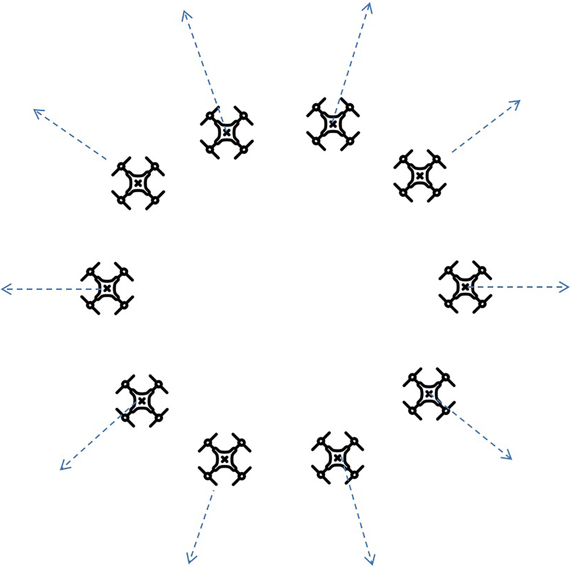
Second Scenario: 10 UAVs. UAV: unmanned aerial vehicle.
Figure 10 shows the number of update messages between simulation time (t = 0) and (t = 1100). The figure aggregates the number of periodic messages broadcasted every 10 s. It can be seen that the number of periodic messages increases steadily between (t = 0 and t = 130) as UAVs are taking off. Then during the period where all 10 UAVs are in flight, the number of periodic messages settles at 10. Finally (at t = 560), and as UAVs start reaching their destinations the number of periodic messages starts declining. The Communication log is an excellent, high-level source to know what has been going on during the simulation.

An aggregate of the number of periodic update message during 10 s interval.
Third scenario: Scalability and collisions
In this scenario, as shown in Figure 11, the scalability of the UTSim is demonstrated by attempting to simulate as many as 1500 UAVs to fly simultaneously. In addition, the previous two scenarios have been orchestrated carefully to avoid collision between UAVs. However, in this scenario, each UAV is given a target and if two UAVs were too close to each other, they were allowed to crash and collide. This scenario was repeated multiple times, each time with a different number of UAVs. Indeed the scenario was run for these number of UAVs: {20, 40, 60, 80, 100, 150, 200, 300, 400, 500, 750, 1000, 1500}. The area where this scenario has been conducted was fixed to be 1 Km × 1 Km. The starting and ending points of the UAVs were completely random.

Third Scenario: Colliding UAVs. UAV: unmanned aerial vehicle.
Figure 12 shows the absolute number of collisions recorded for each run with a different number of UAVs. For example, when there were 750 UAVs, slightly less than 600 UAVs have collided with each other. The figure shows that the number of collisions is linear and directly proportional to the number of UAVs.

Number of collided UAVs versus number of total starting UAVs. UAV: unmanned aerial vehicle.
Figure 13, illustrates the percentage of the UAVs that have ended up colliding out of the initial starting UAVs. It can be seen that the percentage rises exponentially as the number of UAVs increases, and afterward, this percentage saturates. For example, if there are 200 UAVs, half of this is expected to collide. Of course, it is worth noting that in this scenario all UAVs travel at the same altitude and all have no collision avoidance techniques.

Percentage of collided UAVs versus total number of UAVs. UAV: unmanned aerial vehicle.
Finally, in the same scenario, Figure 14 shows the number of messages exchanged between UAVs as the number of UAVs increases. It can be seen that the number of Update Messages does not increase much as it is tied to the number of UAVs. However, the Total Number of messages drastically increases as the number of UAVs increases. This is due to the interaction between different UAVs as they come in and out of each others’ sensing range. The total number of messages is expected to be in the order of n2, while the number of update messages is in the order of n, where n is the number of UAVs.

Number of periodic update and total messages versus the number of UAVs. UAV: unmanned aerial vehicle.
Conclusion
As unmanned aerial systems are continuously increasing and becoming part of more applications, the embedding of UAVs in the national aerospace has become a must. Researchers have started working on the integration of UAVs in current air traffic. This kind of research is quite expensive if it is physically performed. The need for simulators that are easy to use and provide researchers with tools an capabilities to evaluate their proposed algorithms and retrieve useful information to assist in this task, the need for such simulators is vital. In this work, a simulator called UTSim is proposed. The simulator enables researchers to simulate air traffic integration scenarios and empowers them with the tools to design, develop and test air traffic integration and navigation algorithms. UTSim enables researchers to specify properties of the environment, the number, and the type of UAVs, in addition to protocols and algorithms to manage air traffic integration issues like communication, path planning, collision avoidance and more. The proposed simulator has been explained in detail and several simulation scenarios have been presented to illustrate the capabilities of the simulator.
Footnotes
Declaration of conflicting interests
The author(s) declared no potential conflicts of interest with respect to the research, authorship, and/or publication of this article.
Funding
The author(s) received no financial support for the research, authorship, and/or publication of this article.