
Abstract
In this article, a method for two-dimensional scanning path planning based on robot is proposed. In this method, a section division algorithm based on neighborhood search method for scanning orientation determination is firstly produced. The scanning paths which meet constraints of the system are then generated. Finally, the experiment is carried out on robot-based scanning platform. The two-dimensional data from scanner and the robot position are combined to form three-dimensional surface data of measured workpiece. The experiment results verify the effectiveness of proposed method.
Introduction
Three-dimensional (3-D) information of workpiece can be automatically collected by laser scanning which has been widely used in surface detection, reverse engineering, data visualization, computer-aided design, virtual reality environment, digital cultural relics, and so on. 1,2 Laser scanning is an active and noncontact measurement technology. It has many advantages, such as no damage, high accuracy, fast speed, and easy realization of automatic measurement. 3 Laser scanning sensors based on laser triangulation principle have been widely installed in coordinate measuring machines, manipulators, high precision mobile platforms and other devices, and have been combined with stereovision technology to build a simple, fast, flexible, and effective measurement system. 4 Scanning path planning is one of the key technologies to realize automatic scanning. The results of planning directly determine quality, efficiency, and security of scanning.
Many researchers have studied the model-based scanning path planning algorithms combined with different 3-D measurement technologies, which ensure that the measurement of workpiece can be carried out efficiently and completely. 5,6 EIMaraghy and Yang 7 introduced a clustering algorithm for laser scanning. The view cone is introduced to analyze visibility, and feature recognition technology based on ray tracing algorithm is used to improve accuracy, and finally the simulation experiment is carried out on the freeform surface. Lee and Park 8 sampled measured surface along isoparametric line. The workpiece was scanned automatically using a three-axis rotating platform in global scanning direction. Son et al. 9 –11 first sampled the workpiece surface, then proposed an optimal scanning path algorithm for various scanning constraints, and carried out the registration of scanning data, as well as the comparative analysis of measurement data and design data. Some researchers used vision-based system to detect the workpiece surface. 12 Based on computer vision, defect detection technology used industrial camera to obtain the image information of the object surface and used the corresponding image processing method to process the image and complete the detection. 13,14 Chen and Li 15 proposed a shortest scanning path planning method based on hierarchical genetic algorithm for the constraints of visibility, field of view, depth of field, imaging parameters, and kinematic accessibility in the scanning process of digital cameras. Firstly, genetic algorithm is used to calculate the poses of the minimum viewpoints that can scan measured workpiece completely, and then Christofides algorithm is used to obtain the shortest scanning path through these viewpoints. The vision-based detection method has the outstanding advantages of noncontact, high accuracy, and automation, but the system often requires complicated image processing. Fernandez et al. 16 installed line laser on Coordinate measuring machine (CMM) to form an automatic scanning system, analyzed the constraints of scanning system and CMM, and proposed a nonocclusion and collision-free scanning trajectory planning algorithm. Martinez et al. 17 proposed a viewpoint planning scanning algorithm for defect detection of automobile headlamp glass. The view sequence is found by clustering, and genetic algorithm is used to optimize the number of views and their positions and postures in space. Wang 18 studied pose planning algorithm of laser scanner based on clustering algorithm. The minimum required poses and the set of measurement points under each viewpoint are calculated. Li 19 proposed a viewpoint planning algorithm based on minimum bounding box and the scanning cone. Raffaeli et al. 20 proposed a combined viewpoint planning method. Different clustering methods of sampling points are selected according to different detection processes, and the optimal scanning view sequence is obtained by iterative method.
Most of scanning path planning algorithms mentioned above are for area scanning system. In the process of area scanning, it is difficult to satisfy the constraint of field depth for measured surface with large curvature change which is in the same grating pattern projection region. In addition, the viewpoint and path generation method in surface scanning algorithm is not suitable for line scanning system. Especially, scanning path based on two-dimensional (2-D) laser profile scanner has its own characteristics. In the process of laser contour scanning, it is necessary to combine the contour data acquired by scanner with position information of actuator to generate 3-D data of workpiece surface. Path planning algorithm based on laser contour scanning studied in this article has important practical and theoretical significance.
The motivation of this work is to develop a path planning algorithm for 2-D laser profile scanning system in which scanning constraints are satisfied and workpiece surface can be scanned efficiently and automatically. The method first calibrates the relationship between the measured surface and the scanned data. In order to achieve high-precision measurement, the scanned surface is divided into sections with meeting several scan constraints. During the process of surface partition, the algorithm based on region growing is proposed. In the divided scanning area, the orientation of scanner is unchanged and the scanning path length is approached by minimizing repetitive scanning area for the high-efficiency measurement.
The rest of this article is organized as follows: system description is presented in the second section; the scanning path planning algorithm is illustrated in the third section; the fourth section describes simulation results of the given method; the experiment results are provided in the fifth section; and finally, the sixth section concludes main points of the research.
System description
The surface of workpiece may not be consistent with CAD model due to errors in production or wear and tear, so it is necessary to scan workpiece to obtain actual data. In this article, a 2-D laser scanning system based on robot is designed to measure the part surface with given CAD model.
Principle of laser scanning
The principle of laser scanning is depicted in Figure 1. The 2-D laser profile scanner uses triangulation principle. It can easily get the location of the laser line which is described as X-axis and the distance between laser scanner and the surface of workpiece which is called Z-axis in the scanner coordinate system. By moving the measured workpiece or scanner, a set of 3-D measurement points are obtained.

Principle of laser scanning.
During the scanning process, the characteristics of scanner and the relative distance between scanner and measured workpiece determine the quality of measured data. Therefore, the constraints shown in Figure 1 are needed to be considered.
Direction angle
θ
T is the angle between scanner orientation

Depth of field
The scanner could only measure the surface data which is in the depth of field at one scanning time. Supposing that a point in the scanner coordinate system is (x
s, 0, z
s), the equation (2) needs to be satisfied

The best distance (H)
The distance H is from laser source to the scanning reference plane which located in the half depth of field. It can enable laser beam to be focused on reference plane.
Width of scanning (w)
Width of scanning is the width of laser beam which locates in the half depth of field of view, which is also the length of scanning line.
Field of view (FOV)
Area is defined by scanning angle δ and scanning width, within which the scanner can scan points.
Angle of field of view (δ)
Angle of laser beam plane.
Collisionless constraints
During scanning process, ensure that the scanner does not collide with robot or workpiece.
Composition of laser scanning system
The laser scanning system is mainly composed of a 2-D laser scanner and a six-degree of freedom industrial robot. The scanner is mounted at the end of the industrial robot. As shown in Figure 2, OBXBYBZB is base coordinate system of robot, the OEXEYEZE is end coordinate system of robot, the OSXSYSZS is scanner coordinate system, and the OOXOYOZO is coordinate system of measured workpiece. The line laser profile scanner can only measure the key point information of one scanning line on workpiece surface at a time, so in order to obtain the whole surface information, the scanner is moved by robot. Firstly, the position information of measured workpiece surface on X-axis and Z-axis is obtained, and then, the Y-axis is gained by moving along the planned path driven by robot. The complete 3-D data of measured workpiece surface can be achieved.

Laser scanning.
Goal analysis of scanning path planning
The goal of scanning path planning is to generate a robot path along which the robot drives laser sensor to scan workpiece surface at different viewpoints to obtain surface data. After scanning has been completed, the scanning data obtained from different viewpoints are joined together to form workpiece surface.
Based on CAD model of workpiece, the pose of viewpoint in scanning process is firstly calculated in workpiece coordinate system and then transformed into base coordinate system of robot to carry out scanning process. The relationship between coordinate systems is shown in Figure 3, and coordinate transformation is shown in equation (3).

Transformation of coordinate systems.
As shown in Figure 3, BTE is the rotation transformation matrix from OEXEYEZE to OBXBYBZB , ETS is from OSXSYSZS to OEXEYEZE , BTO is from OOXOYOZO to OBXBYBZB , OTS is from OSXSYSZS to OOXOYOZO

In equation (3), BTE is used to control the motion of robot, which is the goal of scanning path planning and obtained by BTO , OTS , and ETS ; BTO can be obtained by locating measured workpiece; OTS can be obtained by calculating viewpoint in workpiece coordinate system; and ETS is related to the pose of scanner installed at the end of robot, which could be obtained by calibration. Therefore, in order to obtain path of the end-effector of robot in scanning process, the unknown parameters in equation (3) need to be calculated.
Neighborhood search method
The scanned workpiece is based on triangular mesh model which is commonly described by stereolithography (STL) file format. STL file format uses triangular facets to represent 3-D entity model. Half-edge data structure is used in the topology reconstruction of triangular meshes. 21 After reconstructing the above patches, a patch neighborhood search algorithm is proposed, which can search n-order neighborhood of patches. As shown in Figure 4, f 0 be a facet in mesh model, and IF 0 be the index of facet f 0. IFfi is a set of adjacent facets of the corresponding facet fi . The algorithm for obtaining n-order neighborhood of facet f 0 is as follows:
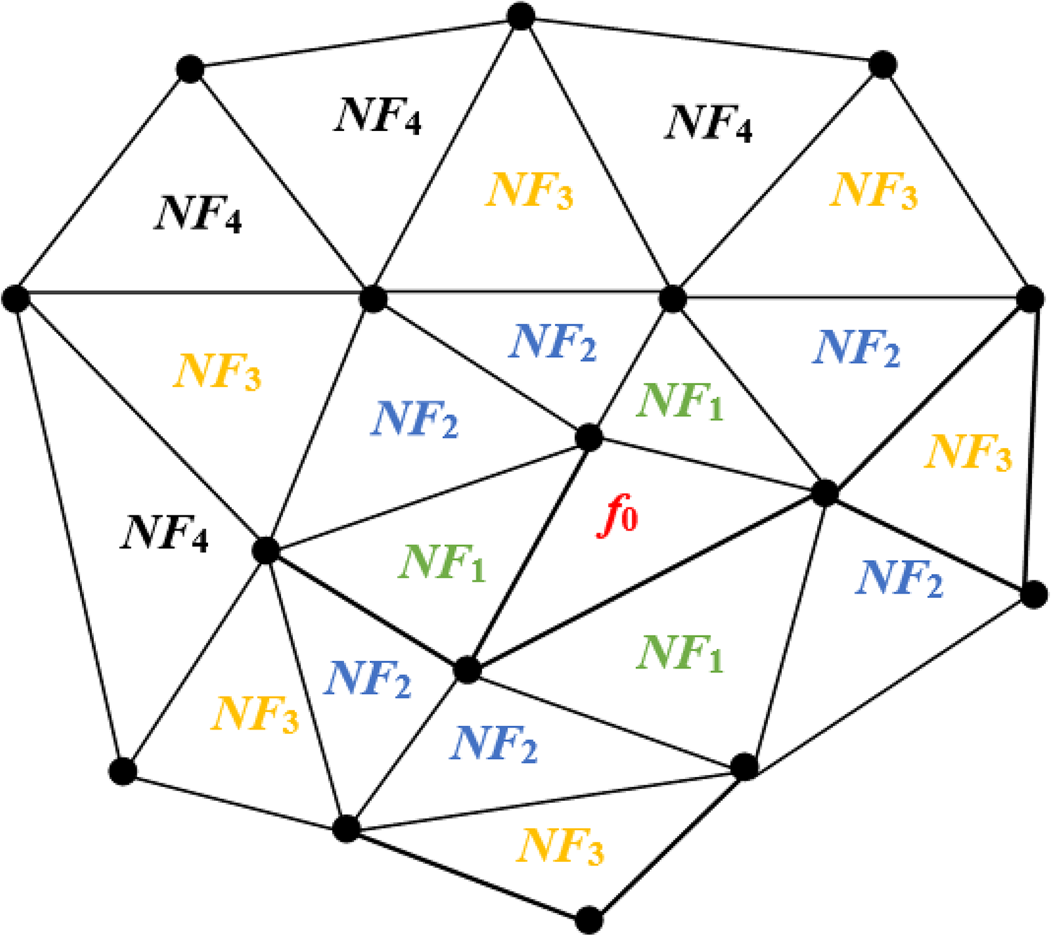
Triangular neighborhood search.
Step 1: Find the first-order neighborhood NH 1 of the facet f 0. Firstly, three half edges contained in f 0 are found. Then, the corresponding neighborhood half edge is found. The neighborhood facet set of f 0 is found, which is called first-order neighborhood face set

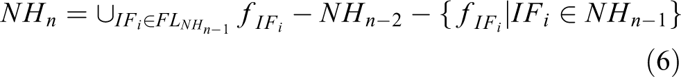
Step 2: Find the second-order neighborhood NH 2 of the facet f 0. NH 2 is obtained by searching facets in the first-order neighborhood

Step 3: Find the n-order neighborhood NHn of the facet f 0. NHn is obtained by searching the facets in the N − 1 order neighborhood
Calibration of system hand–eye parameters
The rotation transformation matrix ETS in equation (3) needs to be calibrated in order to realize the goal of path planning. It is also called hand–eye parameters of scanning system. The calibration is to obtain relationship between scanner and the end of industrial robot

According to the definition of transformation matrix in equation (7), the vectors [nx , ny , nz ]T, [ox , oy , oz ]T, and [ax , ay , az ]T are unit orthogonal vectors.
For a fixed point in the world coordinate system, such as point p in Figure 5, the position information in the scanner coordinate system varies at each scanning time. Taking base coordinate system of robot as world coordinate system, when laser sensor scans the point in different poses, equation (8) is obtained


Diagram of calibration.
In equation (8), SPp (i) is coordinate of space point p in scanner coordinate system at the ith scanning time
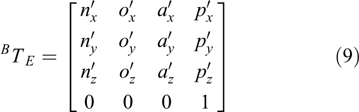

BTE , which is in equation (9), can be obtained from robot controller. ETS , which is in equation (10), is the matrix which needs to be computed. SPp is the coordinate of the point achieved from scanner. Equation (11) could be obtained from equation (8)

Since the scanner can only get 2-D coordinates X and Z of the points, equation (12) can be obtained from equation (11)

Because of unit orthogonal relation, two equations are generated
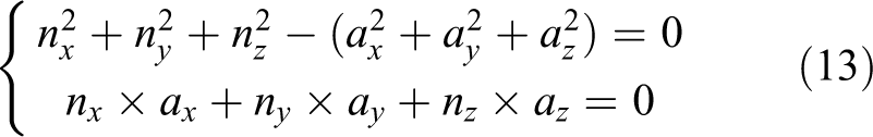
For a fixed point in world coordinate system, equations (12) and (13) can be obtained when scanned with two different poses. Three points at least in space are needed to obtain calibration parameters. In order to improve the accuracy of calculation, five points which are not in the same plane are selected for scanning calibration. Each point is scanned three times. At the same time, the pose parameters of robot end relative to the base coordinate system are recorded.
Scanning path planning algorithm
In this article, a laser sensor is fixed at the end of robot. The robot drives laser sensor to scan measured workpiece. In process of scanning, the constraints must be satisfied. In order to ensure the surface information of workpiece to be collected, it is necessary to plan the pose of scanner in advance. In addition, because the scanner can only detect the length of a scanning line at a time, it is necessary to plan scanning path to ensure that the whole workpiece surface can be completely detected.
Regional division of workpiece surface
When the orientation of scanner (Sz ) is parallel to the normal vector of workpiece surface, the effect of obtaining point cloud is the best. However, in order to reduce additional operation time caused by frequent changes in the orientation of scanner, the surface of measured workpiece is divided to ensure that the scanner orientation is constant in each section. That is to say, the angle between the orientation of scanner (Sz ) and the normal vector of all facets in the section is within the threshold of direction angle.
Steps of regional division are as follows:
Step 1: Traverse all unmarked faces and find out two facets with the largest normal vector angle, as shown in Figure 6, the green and blue facets have the largest normal vector angle θ. If the angle between the two faces satisfies θ < 2θ T, all faces can be scanned in a viewpoint. If the angle does not satisfy this condition, then go to the next step.

Selection of seed patch.
Step 2: Two patches with the largest angle between normal vectors are regarded as seed triangle patches fi and fj , where i ≠ 0 and j ≠ 0. By using patch neighborhood search method, a scanning area Φ i is composed of patches, and the angles between these patches and the patch fi is less than 2θ T. The scanning area Φ j is similarly achieved. The planned patches are marked.
Step 3: Calculate the average normal vectors of initial scanning area, then detect direction angle for each face in the area, and cancel the marking of the face that does not satisfy the angle of view constraint, and determine scanning area. If all the patches are marked, the division is end, otherwise go to step 1.
Determination of scanner orientation
The direction of scanner is Z-axis of scanner coordinate system. In the region that satisfies direction angle constraint, the direction of scanner Sz is defined as opposite direction of the mean of normal vectors of all facets in the region, as shown in Figure 7. The orientation of scanner is calculated according to equation (14)
where m is the number of triangular patches in the scanning area,
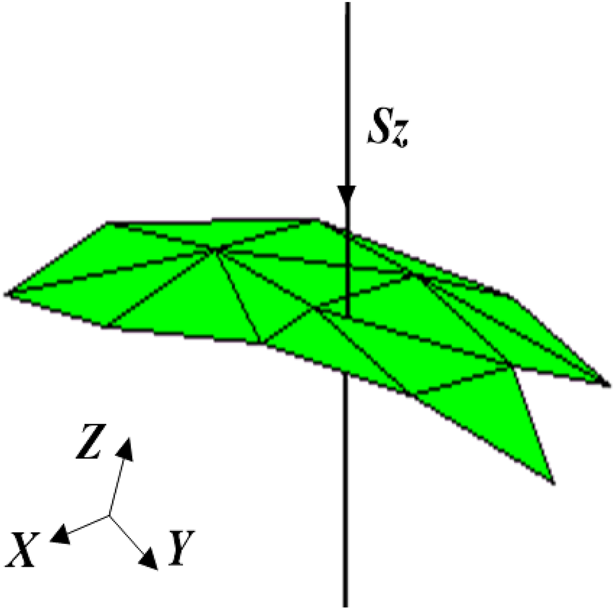
Mean normal vector.
Generation of scanning viewpoint
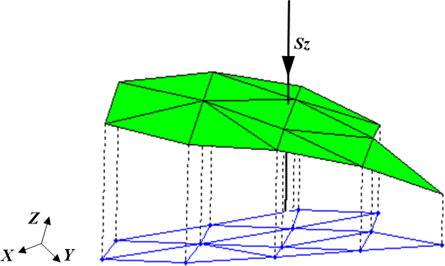
The vertices of all facets in the region are projected onto Sz , as shown in Figure 8. The coordinates of projection points are calculated according to equation (15). Then the maximum distance between projection points is determined

where vi is the vertex coordinate of the facet.

Projection of vertices in faces to Sz direction.
Calculation of the maximum distance among projection points in Sz direction is shown in Figure 9. The red points represent projection points from vertices of all facets in the area, and the blue circles represent the highest and lowest points in this direction. ΔH is the maximum distance of all projection points in the direction of Sz , which is calculated according to equation (16), and pH and pL are the highest projection point and the lowest projection point in the −Sz direction


Distance of projection points in Sz direction.
In Figure 9, if ΔH ≤ h, all facets belong to the same depth range and can be scanned in the same optimal distance plane; if ΔH > h, facets in the same Sz direction need to be classified according to the depth range. The classified data are calculated by equation (17), in which ⌊ ⌋ represents downward rounding
Generation of scanning paths
The facet which contains point Oj and is vertical to Sz is labeled Π j , and the point is calculated by equation (18). Firstly, the patches satisfying depth constraints in the scanning area are projected onto the plane Π j . The projection is calculated by equation (19), and the projection effect is shown in Figure 10. After projection, the polygon formed by the facets in the plane Π j is shown in Figure 11


where pij is coordinate of projection point and vi represents vertex coordinates of facet.
Projection of regional patches to plane Π j .

Polygons on projection plane Π j .
In order to obtain scanning path, the convex hull of polygon on the projection plane Π j is calculated according to the Graham scanning algorithm, and then the minimum outer rectangle 22 of convex hull is obtained by rotation method. As shown in Figure 12, the green dotted line represents the minimum convex hull of projected polygon and the red dotted line is the minimum outer rectangle, which is the area to be scanned.

Minimum enclosing rectangle.
In order to reduce turning times of scanning path, the long direction of outer rectangle is taken as the direction of scanner movement, which is Y-axis direction of scanner coordinate system, and the width direction of rectangle is taken as X-axis. As shown in Figure 12, supposing that four points that make up the smallest outer rectangle are OPr 1, OPr 2, OPr 3, and OPr 4 in the workpiece coordinate system. If | OPr 1 OPr 2| > | OPr 1 OPr 4|, the posture of scanner in this area is shown in equation (20)
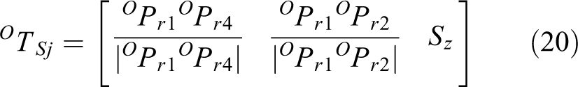
If | OPr 1 OPr 4| ≤ w, the area can be scanned according to one scanning line segment. Otherwise, the width of the smallest rectangle is divided, and the number N of scanning lines in this area is expressed by equation (21), in which ⌈ ⌉ represents upward rounding. The scanning lines in this area are shown in Figure 13. The black line with arrow in the figure is scanning line segment, and each scanning line segment is divided by scanning step, and the scanning viewpoints in projection plane are obtained. Then these points are offset according to the constraints of the best distance, as depicted in equation (22). The global scanning viewpoint OPS in workpiece coordinate system is obtained. The blue line is composed of global scanning viewpoint, and the arrow represents the direction of scanner’s movement and the posture of scanner is constant during the whole scanning process. Finally, different scanning lines are connected to form scanning path of the region


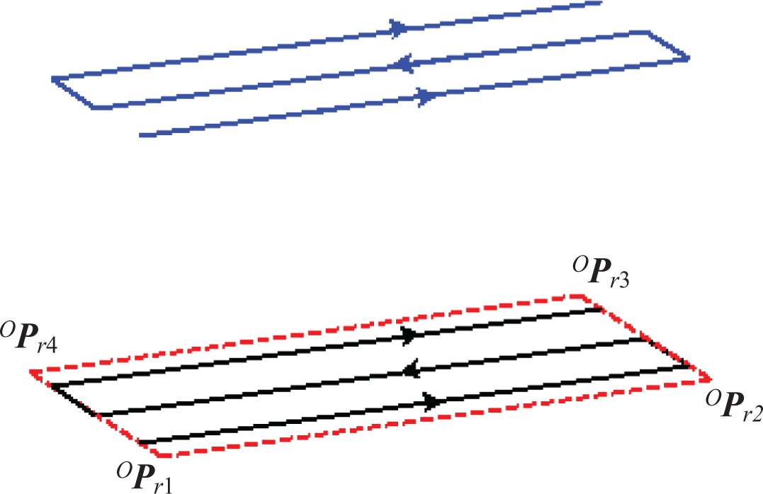
Scanning path in one scanned area.
In the scanning process, collision often occurs between scanner and workpiece, so this article mainly detects whether there is collision between the end tool and scanned workpiece. The path is updated when collision occurs. In order to detect collision, the poses of scanner and workpiece need to transform to the same coordinate system which is the base coordinate system of robot. The box-based algorithm 23 is adopted for collision detection.
Simulation results
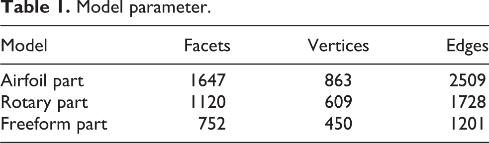
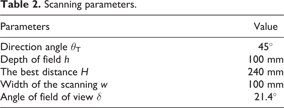
The above algorithm is based on facets and requires the edge length of the facets to be less than the width of scanning line, the triangular mesh model of workpiece is refined by dichotomy, 24 and then path planning is carried out. The refined model parameters are shown in Table 1, and the scanning constraints are stated in Table 2.
Model parameter.
Scanning parameters.
Airfoil part model and scanning path
The model of airfoil part is shown in Figure 14. Firstly, the maximum angle between the normal vectors of triangular surface of airfoil model is traversed, θ max = 53.4° and θ max < 2θ T. It is found that all the facets in the model satisfy the constraints of view angle. Therefore, during the scanning process of airfoil model, the same scanner can be used to scan the whole workpiece surface, which is calculated according to equation (14). Then △H = 124 mm is calculated by equations (15) and (16), and k = 2 is calculated by equation (17). The model is divided into two regions, pink and green, as shown in Figure 15. Finally, the final scan path is generated according to the method in the third section.

Airfoil part model.

Scanning paths for airfoil part.
When calculating the scanning path, the facets of pink and green areas in Figure 15 are projected to different projection planes to calculate the minimum enclosing rectangle in different areas, such as the red dotted rectangle. The pose of scanning viewpoint is obtained from equation (20). Then the scanning line segments are calculated according to scanning width. The blue and black lines in the red dotted frame are calculated. Finally, the scanning path composed of scanning viewpoints in the workpiece coordinate system is calculated according to equation (22) as path_a and path_b in Figure 15.
Through the calculation of scanning path, it is obtained that the facets of airfoil part are located in the same direction during scanning, but the scanning paths path_a and path_b are located in two different depth of field areas.
Rotary part model and scanning path
The model of rotary workpiece is shown in Figure 16. The maximum angle between normal vectors of triangular patches in the model is found, and θ max = 100.3°. For θ max > 2θ T, it is necessary to change the orientation of scanner in order to achieve complete scanning of workpiece surface.

Rotary part model.
Firstly, all unmarked facets of workpiece are traversed, two facets fi = 1 and fj = 1049 which are with the largest angle are selected as seed triangle facets, and the neighborhood of seed facets are searched, respectively. The scanning areas Φ i is constituted by the facets, and the angles between these facets and fi are smaller than 2θ T. Φ j is the same. The facets in the scanning area are marked. Then, the view angle is detected in regions Φ i and Φ j , and the facets which do not satisfy the view angle constraints are cancelled. The process of generating scanning paths needs to continue until all facets are marked. Finally, six different scanning areas are generated. Then, the Sz is computed according to equation (14). By equations (15) and (16), the patches in each region satisfy ΔH < h. The final scan path is then generated for each region according to the method in the third section, as shown in Figure 17.

Scanning paths for rotary part.
Freeform part model and scanning path
The model of freeform workpiece is shown in Figure 18. The maximum angle between normal vectors of triangular patches in the model is found, and θ max = 95.7°. For θ max > 2θ T, it is necessary to change the orientation of scanner in order to achieve complete scanning of workpiece surface.
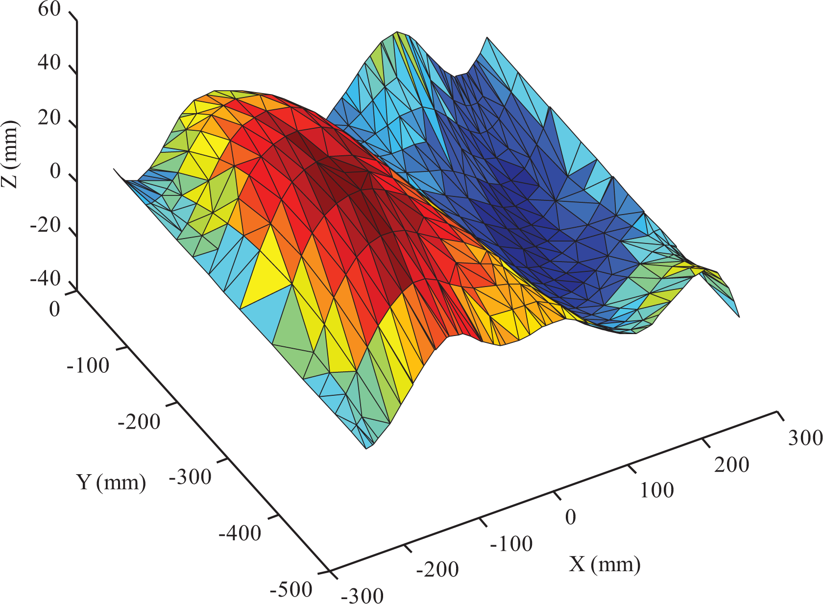
Freeform part model.
Firstly, all unmarked facets of workpiece are traversed, two facets (fi = 8 and fj = 710) which have the largest angle are selected as seed triangle facets, and the neighborhood of seed facets are searched, respectively. The scanning areas Φ i is constituted by the facets, and the angles between these facets and fi are smaller than 2θ T. Φ j is the same. The facets in the scanning area are marked. Then, the view angle is detected in regions Φ i and Φ j , and the facets which do not satisfy the view angle constraints are unmarked. Then, the Sz is computed according to equation (14). By equations (15) and (16), the patches in each region satisfy ΔH < h. The process of generating scanning paths needs to continue until all facets are marked. Finally, three different scanning areas are generated, and the final scan path is then generated for each region which is shown in Figure 19.

Scanning paths for freeform part.
Algorithm comparison
The algorithm proposed in the study by Wu et al. 24 is used to divide workpiece surface and generate scanning path. The path planning results for rotary part and freeform part are shown in Figures 20 and 21.

Scanning paths for rotary part by Wu et al. 24

Scanning paths for freeform part by Wu et al. 24
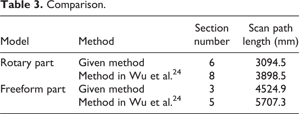
The algorithm proposed in this article is compared with that in the study by Wu et al. 24 The results are shown in Table 3. By comparing two algorithms, the section number obtained by this algorithm is less than that calculated by Wu et al., 24 and the total path lengths computed are shorter than that produced by Wu et al. 24 by 804 mm (for rotary part) and 1182.4 mm (for freeform part), respectively. It can be concluded that the proposed algorithm can reduce the number of sections and the total length of scanning paths.
Comparison.
Scanning experiment
In equation (3), the hand–eye parameters of scanning system need to be computed firstly. The data obtained during calibration process are shown in Table 4. The rotation matrix from the robot end to the robot base coordinate system is expressed by quaternions (q 1, q 2, q 3, q 4) and the translate vector is expressed by (x B, y B, z B), and they are all obtained from robot controller. The coordinates of the fixed point in the scanner coordinate system are labeled as (x S, 0, z S), which are achieved from the scanner. Using data in Table 4 and the above calibration method, the transformation matrix ETS is calculated by the iterative least squares algorithm 25

Calibration data.

The method of locating workpiece refers to the method in the study by Wu. 26 The scanner installed at the end of robot scans several corners of airfoil part and reads the pose of robot end from robot controller. The coordinates of workpiece corners in the base coordinate system of robot can be obtained by equation (24). The coordinate values of corners in the workpiece coordinate system are known, so that the pose of workpiece in the robot coordinate system can be obtained, and the workpiece can be positioned

Experiment of airfoil model and analysis
The scanning system is mainly composed of ABB IRB6640 industrial robot and 2-D laser sensor scanCONTROL 2600-100. The test platform is shown in Figure 22. When the scanner receives trigger command from robot controller, the laser projects a linear laser beam onto the surface profile of workpiece. There are a series of sampling points with approximately equal spacing distribution on the formed scanning line. Then the sensor returns data of sampling points relative to X-axis and Z-axis of scanner coordinate system. Every time the scanner collects data, the robot controller saves pose information of the robot end. In scanning process, the spacing of two continuous laser fringes along the direction of Y-axis in the measuring coordinate system should be set according to requirement of system accuracy.

Scanning experimental platform.
Scanning path planning based on airfoil model includes six steps: hand–eye parameter calibration of scanning system, triangular mesh model processing, scanning path planning, airfoil workpiece positioning, point cloud collection on workpiece surface, and point clouds registration. The main parameters of experiment are as follows: the length of linear laser beam is about 100 mm, the distance between scanner and scanning plane is 240 mm, the depth of field is 100 mm, and the depth resolution is 12 µm. Each scanning line can collect 640 measuring points at a time, and the scanning frequency is 200 Hz, and the measuring speed is 128,000 points/s. During scanning process, the robot acts as the execution of mechanical movement. Laser sensor installed at robot end is driven to scan, and the repetitive positioning accuracy of the robot is 0.5 mm. The scanning step is 1.0 mm.
When the pose of workpiece is known and the hand–eye relationship matrix has been calibrated, the scanning path points at robot end can be obtained by using equation (3). Scanning paths which are shown in Figure 23 are constituted by connecting path points. Scanners collect point clouds of different sections of workpiece surface at different scanning time. When scanning is completed, the data must be transformed into the same coordinate system in order to achieve point clouds registration. According to equation (25), the scanned data can be unified into the base coordinate system of robot. The scanning results are shown in Figure 24(a)

where SPp is the position of scanned point in the scanner coordinate system and BPp is the position of scanned point in the robot base coordinate system.

Scanning paths.

Airfoil model. (a) Scanned model and (b) designed model.
Due to influence of scanning environment, object surface, illumination, and other factors, point clouds obtained by laser scanner often contain noise and outliers. Firstly, scanned data should be pre-processed by removing noise and outliers. After obtaining the surface data of airfoil part, the scanned model is aligned with CAD model, and then the difference threshold is used to judge whether there are defects.
Geomagic Qualify software, as a computer-aided test software, has the characteristics of simplicity and powerful detection function. First, the scanned point cloud model is imported as testing object, and then CAD model is imported as reference object. According to the minimum deviation, the best fitting and alignment function of the software is used to adjust the matching between point cloud and design model continuously. Then using comparative analysis function of the software, the deviation can be generated by 3-D comparison.
The standard deviation between scanned point cloud model and CAD model is 3.0 mm, and the mean deviation is 2.5 mm. Large deviation occurs at the edge of workpiece which is made of pine wood material. The pine material is easy to crack and deform which is the main reason for deviation. When the airfoil workpiece is used as the placement model in the robotic fiber placement, 27 it is necessary to modify the design model according to scanned model to ensure that the subsequent operation of workpiece is based on the actual model. The experimental results show that laser scanner can acquire complete data of workpiece surface according to designed planning path and meet the requirement of surface detection for workpiece.
Conclusions
In this article, a path planning algorithm for 2-D laser scanning system based on robot is produced. Firstly, composition and constraints of scanning system are introduced, and the hand–eye parameters of system are calibrated. Then, based on triangular mesh model, a path planning algorithm for scanning is proposed. In the given method, surface area of workpiece is divided into several regions, and scanning orientations and scanning viewpoints are determined in each region. Then scanning paths are obtained according to minimum enclosing rectangle. During scanning, the scanner will not collide with measured workpiece. Finally, the scanning of airfoil part is carried out on the experiment platform, and scanned model is obtained. Compared with design model, the comparison result shows that the scanning path algorithm is effective.
In the future work, there is a need to consider the relationship between the constantly changing scanning direction and scanning path length, which can make full use of the flexibility of the robot. Additionally, the proposed method assumes that the CAD model of the part is given. Another work is expanding our system to unknown part.
Footnotes
Declaration of conflicting interests
The author(s) declared no potential conflicts of interest with respect to the research, authorship, and/or publication of this article.
Funding
The author(s) disclosed receipt of the following financial support for the research, authorship, and/or publication of this article: This work is partly supported by The National Natural Science Foundation of China (grant no. 51405486) and Shanxi Key Laboratory of Advanced Manufacturing Technology Foundation (grant no. XJZZ201703).