
Abstract
Collision may occur during the grinding of a workpiece by a robot sand belt. To solve this problem, a collision-free planning algorithm for the robot motion path is developed based on the collision layer method. Collision-free planning of the robot motion path is studied, and a means to adjust the machining frame on the belt is determined (i.e. moving along the axis of the belt and rotating around the tangent line). The planning curve is rapidly found on the collision layer using neighborhood search and recursive methods, and the amount of collision detection is significantly reduced. The planning curve is transformed into the robot motion path. Simulation and experimentation show that the amount of collision detection required by the proposed algorithm is 3.86% less than that required by a method using a complete collision layer. Moreover, the robot grinds the workpiece without collision. The proposed method is simple, stable, and easy to implement and possesses a good engineering application value.
Keywords
Introduction
Robot belt grinding can overcome the shortcomings of manual belt grinding because of its high efficiency and precision. Therefore, it has been widely used in industrial production. With the shape of the workpiece becoming increasingly complex, the robot in the belt grinding process is prone to different types of collision, such as workpiece–tool and robot–tool collision. Therefore, studying the collision-free planning of the robot motion path is necessary.
The collision-free path planning problem in robot belt grinding is similar to that in non-interference tool path planning in numerical controlled (NC) belt grinding. The NC system involves local and global interference. 1 Local interference means that the tool interferes with the workpiece during machining. Local interference is divided into local and rear gouging. Local gouging refers to the interference between the cutter and workpiece near the cutter contact, and rear gouging refers to the interference between the other parts of the tool and the workpiece. Global interference refers to the interference between the workpiece and machine or between the tool and machine during machining. Global interference is more harmful than local interference because it can damage machines. A common solution to the interference problem is to adjust the tool orientation. Sturz method, 2 –6 visibility and accessibility method, 7 –9 principal-axis method (PAM), 10,11 and Arc-intersect method (AIM) 12,13 are commonly adopted methods. Sturz method involves less calculation and is widely used in commercial software. But the tool path generated by this method is inefficient. Visibility and accessibility method generates the smooth and collision-free tool path, but it has higher requirements for computing resources. The tool path generated by PAM has wider tool path interval and uniform scallops. But the tool path becomes more complicated with the increase of the tool path interval. AIM is an area-based method that generates gouge-free tool positions without the use of iterative gouge-check and correction algorithms. Xu et al. 14 presented a tool orientation smoothing method based on the non-uniform rational basis spline (NURBS) envelope. In this method, tool orientation is adjusted by evaluating the intersection of the NURBS envelope so that no collision occurs during machining. This method has been successfully applied to the formation of a collision-free tool path in blade processing. Li and Jerard 15 proposed a tool path collision avoidance method based on angle adjustment. The method transforms a parametric surface into a mesh surface and then determines the corresponding cutter location for each triangular piece. Subsequently, the position and angle of the tool are adjusted through interference detection to generate a tool path without gouging. Wang et al. 16 proposed a tool orientation collision-free planning method based on the graphics-assisted approach. In this method, the visibility and accessibility cones of the cutter contact (CC) points where collisions occur are calculated through graphics-assisted cubic mapping. Afterward, the tool orientation of a CC point is selected from its visibility and accessibility cones. Li and Feng 17 developed a method to avoid rear and side gouging by adopting binary and bisection search methods. However, this method is only applicable to the processing of curved surfaces with small curvature. Robot Master, 18 a plug-in of Master CAM, achieves collision-free robot path planning through the collision layer. The adjustment of the robot end cutter is converted into a planning curve to avoid passing the collision area on the collision layer, and collision-free path planning for the robot is realized. However, this method is usually applied to the robot end clamping tool and is inapplicable to the robot end clamping workpiece. Furthermore, the method requires adjusting the planning curve manually, so its operation is highly complicated.
After applying the collision layer method, the problem of three-dimensional (3-D) robot motion path planning is transformed into a 2-D path planning problem. This transformation simplifies the problem and is intuitively effective. This method has been widely used in actual collision-free robot motion path planning. Path planning methods in 2-D space include C space 19 –21 and artificial potential field. 22 –25 However, these methods need to generate a complete collision layer. That is, extensive collision detection, which is time consuming, is needed. Searching for the optimal curve without a complete collision layer must therefore be studied, and a collision-free planning algorithm must be established for the robot motion path.
To address the problem of collision-free planning of the robot motion path in robotic belt grinding systems, the principle of such planning is analyzed in this study in “Principle of collision-free planning of robot motion path” section. A method to adjust the machining frame on the belt is determined and a corresponding model is established in “Principle of machining frame translation along the axis” section. A collision-free path planning method based on the collision layer method is also developed in “Principle of machining frame rotation around the tangent” section. The optimal curve on the collision layer is determined with neighborhood search and recursive methods. As a result, the amount of collision detection is reduced. Subsequently, “Collision-free planning algorithm for robot motion path” section creates a program to achieve a collision-free robot path planning algorithm. Simulation of collision-free planning of robot motion path and robot grinding experiments verify the feasibility of the algorithm in “Simulation and grinding experiment on the collision-free planning algorithm for the robot motion path” section.
The algorithm proposed in this article can automatically and quickly carry out collision free planning for the robot motion path. Compared to the generation of the complete collision layer, the algorithm can greatly reduce the number of collision detection and improve the planning speed of the algorithm.
Principle of collision-free planning of robot motion path
Robot belt grinding is realized as follows: (1) the grinding path of the workpiece is generated according to the workpiece model through automatic path planning techniques, (2) the workpiece grinding path is transformed into the robot motion path, and (3) the robot grinds the workpiece according to the motion path.
As shown in Figure 1, converting the grinding path of the workpiece into the robot motion path involves mapping the CC points on the grinding path to the corresponding path points on the robot motion path. A frame is added to each CC point on the workpiece grinding path with the same
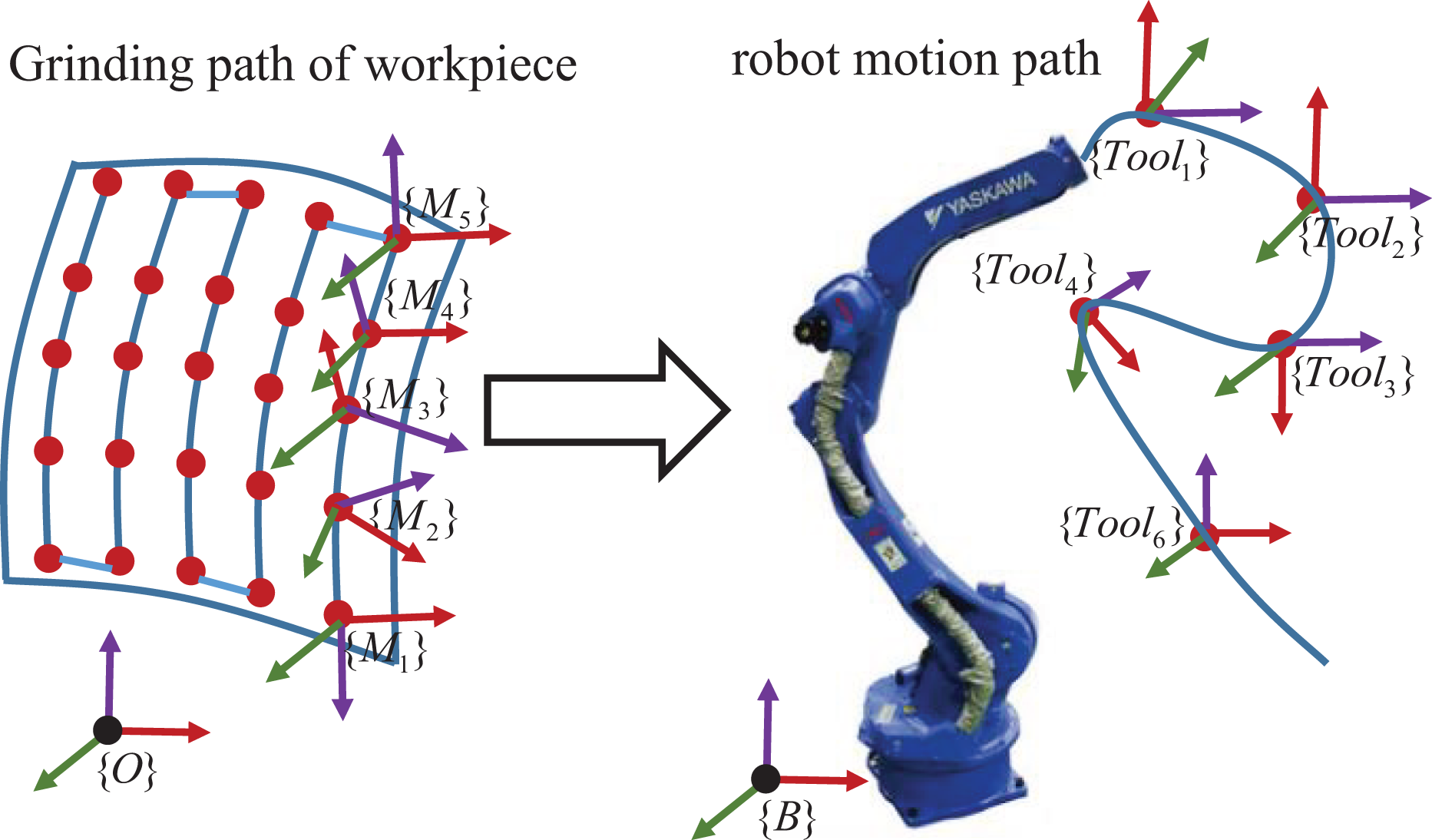
Workpiece grinding path transformed into the robot motion path.
As shown in Figure 2, machining frame {M′} is defined at a point on the belt, and its position and orientation are denoted by

Robot holds the workpiece for grinding.
After generating the workpiece grinding path and adding a frame to each CC point

Then

in which

The Cartesian space position and orientation of each point in the robot motion path are obtained. According to the robot inverse kinematics solution algorithm in the literature
26,27
and
The precondition of robot collision-free path planning is to ensure that the machining quality meets established requirements. According to equation (2), when the workpiece grinding path is generated,
The adjustment of

Machining frame {M′} and initial machining frame
Principle of machining frame translation along the axis
As shown in Figure 4(a), the workpiece collides with the tool when the robot is grinding a CC point (yellow spot in Figure 4) on the workpiece. If machining frame {M′} translates along the axis of the contact wheel (direction of

Collision between the workpiece and tool and {M′} translating along the axis.
Figure 5 illustrates the principle which the machining frame translates along the axis of the contact wheel. The blue frame is the initial machining frame

Diagram of machining frame axial translation.
In Figure 5, the parameter a is the distance of machining frame translation. When the radius of the contact wheel is R and the width of the belt is W, the range of a is

where

Principle of machining frame rotation around the tangent line
As shown in Figure 6(a), a CC point of the grinding path is machined when the machining frame translates axially to the edge of the sand belt. The workpiece collides with the tool because of the workpiece shape. When {M′} rotates at angle α around

Collision between the workpiece and tool and {M′} rotating around the tangent line.
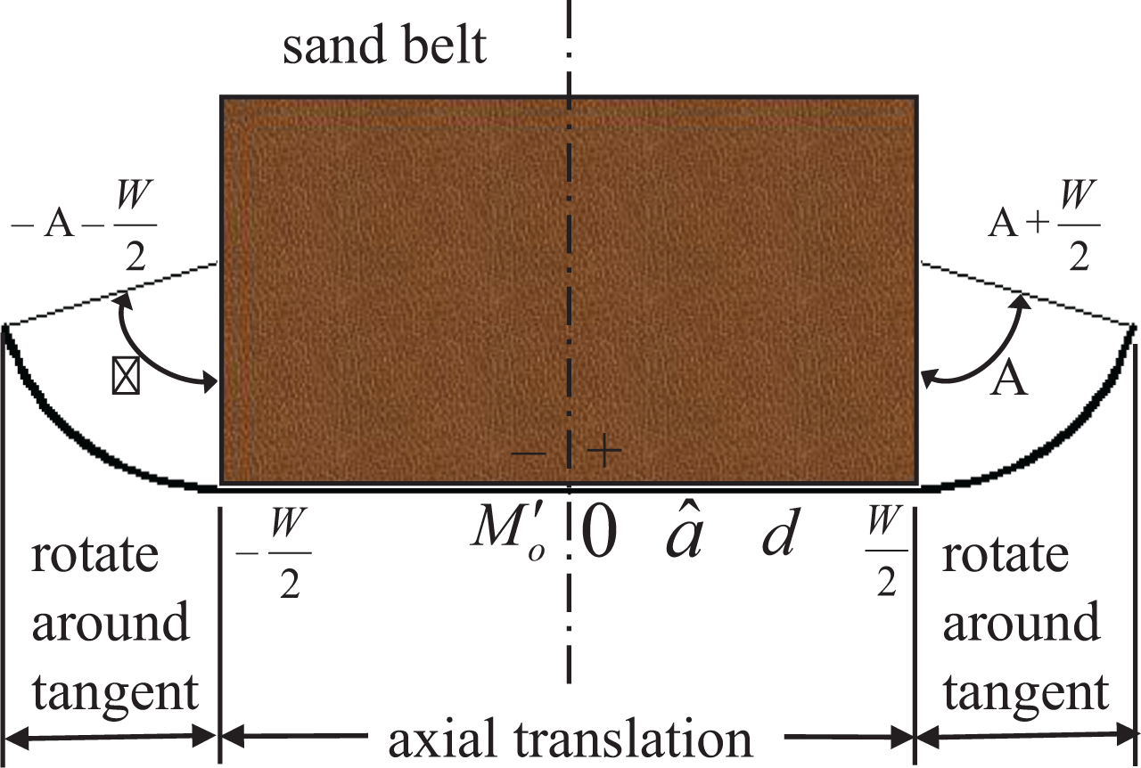
Figure 7 shows a schematic of the rotation of machining frame {M′} around the tangent line, and the arrow on the tangent line represents the forward direction. This rotation adjustment is performed only when {M′} is axially shifted to the edge of the sand belt; otherwise, the workpiece will definitely collide with the tool.

Machining frame rotates around the tangent line.
In Figure 7, when the maximum angle of rotation of the coordinate system around the tangent is Α, the minimum rotation angle is 0.

Integration of two adjustment methods for the machining frame
To facilitate the calculation and realization of the two adjustment methods of the machining coordinate system, the two methods are integrated.
As shown in Figure 8, in establishing coordinate axis

Machining frame {M′} on the coordinate axis
When
Collision-free planning algorithm for robot motion path
Collision-free planning for robot motion path is equivalent to specifying position d on coordinate axis
Based on the robot belt grinding simulation, the collision layer is established for the collision-free robot motion path planning, as shown in Figure 9(a). The abscissa is the index of CC points on the grinding path, and the ordinate is position d of the machining frame on coordinate axis
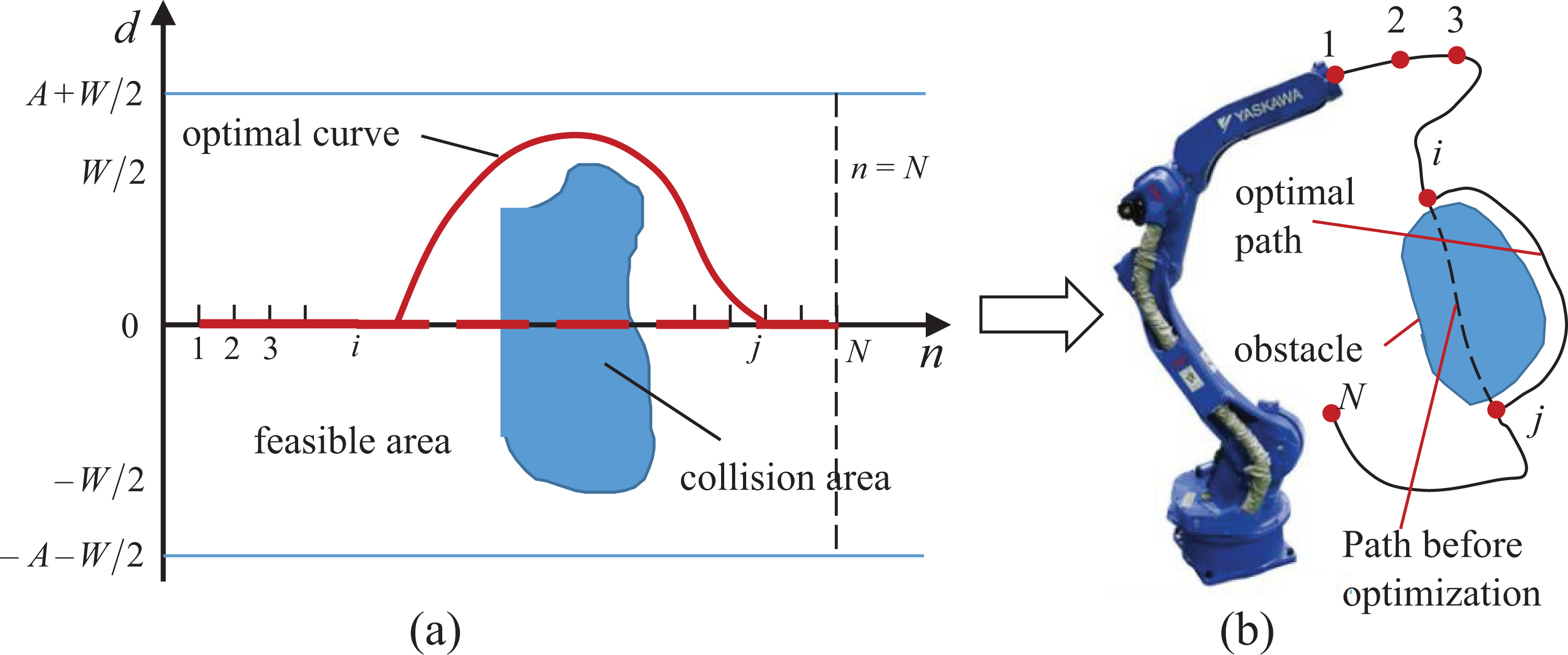
Collision-free planning of robot motion path based on the collision layer.
The robot collision-free path planning is transformed into a model like this: as shown in Figure 9(a), there are N CC points, finding a planning curve starting from n = 1 and ending at n = N in the feasible region in the collision layer. Using the optimized curve to calculate the position of each point on the robot’s motion path, collision-free planning of the robot motion path is realized, as shown in Figure 9(b).
On the collision layer, the set CA represents the collision area, and collision detection can be used to determine whether
If collision occurs when the robot grinds the ith CC point in the simulation, the optimal curve should be found on the collision layer. The most direct method is to generate the collision layer of the ith CC point and its neighboring layers completely and then find the optimal curve on the layer. However, this method is very time-consuming because the entire layer points run through, and collision detection is carried out when the collision layer is generated. Therefore, a planning algorithm is proposed. In the absence of a complete collision layer, the planning curve is quickly found through neighborhood search and recursive methods to realize collision-free planning of the motion path during robot grinding.
The algorithm of collision-free planning of the robot motion path consists of three parts: determination of the midpoint of the collision range, one-way planning curve search algorithm based on the neighborhood search method, and bidirectional planning curve search algorithm based on the recursive method.
Determination of the midpoint of the collision-free range
As shown in Figure 10, the initial curve is a straight line from point (1, 0) to point (N, 0), indicating that the position of {M′} corresponding to all the CC points is d = 0 on

Midpoint of the collision-free interval of machining frame {M′}.
The robot initializes the grinding simulation from the first CC point. When the ith CC point
Assume that, i is the index of current CC point, d is the position of corresponding machining frame Step 1: Step 2: idx represents the index of Step 3: If the first element of Step 4: If the last element of Step 5: idx represents the index of

And put the
Searching algorithm of the one-way planning curve based on neighborhood search method
As shown in Figure 11, when the midpoint of collision-free interval of the ith CC point is found, one of the midpoint m
1 is selected as the starting point. An optimal curve (the red dotted curve) is searched from m
1 point, in the range of

Searching for the one-way planning curve.
In the search for optimal curve, the distance between two machining frames’ corresponding adjacent CC points can’t be too large, because once the distance is too large, the magnitude of robot movement will increase suddenly when robot machines these CC point, so that the quality of grinding is affected. So the neighborhood search method is used to make the optimal curve more flat. As shown in Figure 12, the optimal curve reaches the ith point

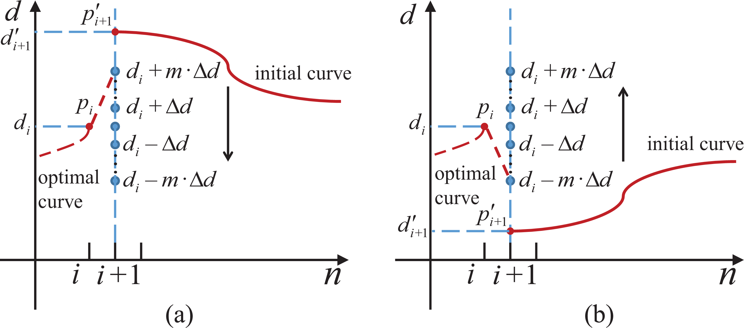
Searching planning curve based on neighborhood search method.
So that the distance between {M′} corresponding to the two adjacent CC points on
In order to improve the efficiency of the search, the value of

where
As shown in Figure 13,

The method of searching the one-way planning curve based on neighborhood search method is as follows. Step 1: input the midpoint of collision-free interval mid as the beginning of optimal curve, the search range Step 2: Δi is the step of the CC point list’s index. Δi is calculated by formula: Step 3: if Step4: if Step 5: when list is gone throughout from beginning to end and collision detection is carried out, determine whether
As shown in Figure 11, the algorithm looks forward the optimal curve for the CC points with the index greater than i. Let
Bidirectional planning curve searching algorithm based on the recursive method
As shown in Figure 14, when the workpiece or robot collides with the tool when machining to the ith CC point, it is necessary to start from the midpoint of a collision-free zone at n = i, as shown in m 1 in Figure 14, respectively, forward and backward to find the planning curves which connect to initial curve, so that the whole curve to avoid the collision area, to achieve the motion path without collision.

Search for bidirectional optimal curves.
The process of basic algorithm of searching a bidirectional optimal curve is calculating the list
As shown in Figure 15, in the bidirectional planning curve finding algorithm, if the collision area is encountered when the planning curve is searched from the point m
1. For example, the curve c in Figure 15 enters the collision area 1 at

Bidirectional optimal curve search algorithm to avoid the collision area.
The bidirectional optimal curve search algorithm based on recursive method is as follows. Step 1: input the index iF
of CC point where collision occurs and calculate the list list of collision-free interval midpoint of the iF
th CC point; Step 2: if list is null, return Step 3: the algorithm jumps to step 4 if search of optimal curve is successful. Otherwise let the index n of CC point where collision occur is equal to Step 4: let Step 5: if planning is successful, the algorithm jumps to step 6, otherwise lets Step 6: return
Collision-free planning algorithm for robot motion path
Integrating the three algorithms discussed above, the robot collision-free path planning algorithm is obtained and it is as follows. Step 1: input the initial machining frame Step 2: calculate all the joint space positions of robot based on Step 3: curve is the list of points of initial curve. Every point of curve represents the position of corresponding machining frame {M′} on the axis Step 4: if Step 5: if there is no collision, let Step 6: if
The list Joints of optimal joint space positions is generated if the collision-free planning of robot motion path is successful. Robot grinds workpiece without collision only if robot carries out those joint positions in Joints in order.
Simulation and grinding experiment on the collision-free planning algorithm for the robot motion path
Simulation of the collision-free planning algorithm
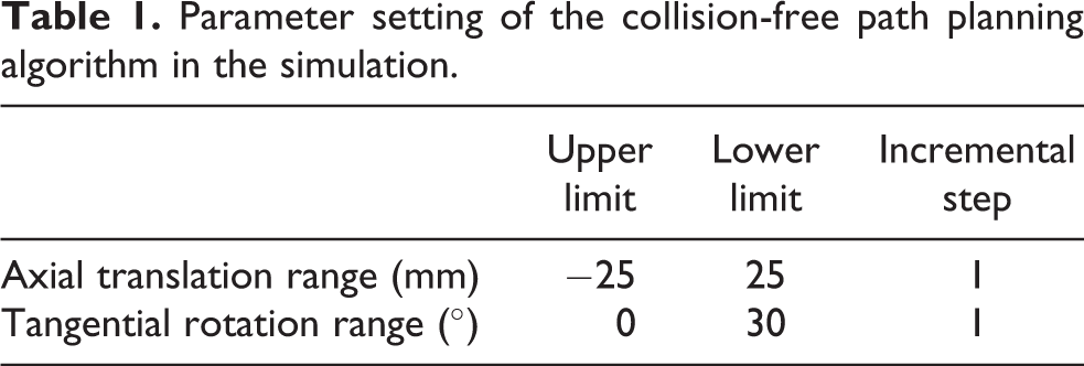
Collision-free planning for the robot motion path is achieved with the V-Rep platform. The simulation scene is shown in Figure 2. The workpiece model is added for grinding in the scene, as shown in Figure 16. Collision detection is performed between the workpiece and other objects in the scene. The parameter settings of the algorithm are shown in Table 1.

Workpiece in the simulation.
Parameter setting of the collision-free path planning algorithm in the simulation.
In the simulation of experimental conditions, as shown in Figure 17, the position and orientation of machining frame {M′} are relative to robot base frame {B}.
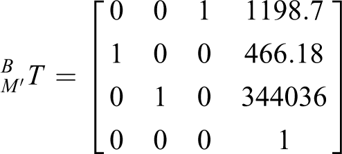

Machining frame {M′} in the simulation.
The axis of the sand belt contact wheel is parallel to
The collision layer generated by the algorithm during the simulation process is shown in Figure 18. In the figure, the blue and green regions are the collision area, and the red curve is the planning curve found by the algorithm in “Collision-free planning algorithm for robot motion path” section. The blue area is the collision area obtained by collision detection in the process of finding the optimal curve. The blue area is 4.73% of the collision area. This result proves that the robot motion path collision-free planning algorithm finds the optimal curve on the collision layer through neighborhood search and recursive methods with only a small amount of collision detection and without knowing the complete collision layer. It realizes robot motion path collision-free planning.

Collision layer during the robot machining the workpiece in the simulation.
Table 2 lists the number of collision detection times for generating a complete collision layer and the number of collision detection times required to find the planning curve with the algorithm in “Collision-free planning algorithm for robot motion path” section. According to data in the table, the latter’s number of collision detection is 3.86% of the former’s, which proves that the algorithm in greatly reduces the number of collision detection compared to the method of generating the entire collision layer.
Comparison of the amount of collision detection instances.

The point of the workpiece surface is sampled to form a point cloud of the workpiece. In Figure 19, distance d from all points in the point cloud to the contact wheel axis is calculated and plotted, and abscissa y is the y-coordinate of the point in {B}. The simulation experimental conditions show that the two sides of the contact wheel are

Analysis of the distance between points and the contact wheel axis.
Grinding experiment on the collision-free planning algorithm for robot motion path
The workpiece is grinded in the robot grinding platform. The material of the workpiece is 45# steel. The type of the sand belt is Little Sun TJ538. The particle size of the sand belt is 100, its width is 50 mm, its perimeter is 2100 mm, and its material is zircon corundum. The robot is Yaskawa MH-24 Robot. When the workpiece is machined, the line speed of the belt is 8 m/s, the robot’s speed of MovL (robot linear movement) is 25 mm/s, and the speed of MovJ (robot joint movement) is 70%. The setting of those speeds is based on the processing requirement, which includes the processing materials and technology. The process of machining is shown in Figure 20. No collision occurs between the workpiece and tool during workpiece machining. The grinded workpiece is shown in Figure 21.

Process of the robot grinding the workpiece.

Comparison of the workpiece before and after grinding. (a) Workpiece before machining; (b) machined workpiece.
Surface roughness is measured after workpiece processing. The measurement equipment is Time Group’s TR200 hand-held roughness meter, and the measurement results are shown in Table 3 according to the division of the area in Figure 22. The average roughness is
Surface roughness of the workpiece after robot grinding.


Roughness of the machined workpiece.
The surface of workpiece after grinding is measured with the trilinear coordinates measuring instrument. The error profile is shown in Figure 23. The error interval of all data points is −0.209 mm to 0.244 mm, the range length is 0.453 mm, the mean error value is 0.057 mm, and the standard deviation is 0.112 mm. Data analysis indicates that, the size accuracy of the workpiece after robot sand belt machining would meet the requirements if the robot motion path has been collision-free optimized.

Shape error distribution of the machined workpiece.
Conclusion
A collision-free algorithm for robot motion path based on the collision layer method is proposed to solve the problem of collision occurring in the process of grinding a workpiece. According to the characteristics of belt grinding, a method to adjust the machining frame on the belt is proposed; axial translation along the belt and tangent rotation are implemented. A method based on neighborhood search and recursive methods is also proposed. Based on the local search method, without searching through every point in the collision layer, a planning curve can be quickly searched in the collision layer, which determines the corresponding joint poses of robot, achieving collision-free planning of the robot’s motion path finally.
The simulation results show that the proposed algorithm can generate a collision-free robot motion path, and collision detection is greatly reduced to 3.86% of the method of generating a complete collision layer. The robot belt grinding experiment shows that the robot grinds the workpiece without collision based on the motion path generated by the algorithm. The quality of the machined workpiece meets the requirements.
Footnotes
Declaration of conflicting interests
The authors declared no potential conflicts of interest with respect to the research, authorship, and/or publication of this article.
Funding
The authors disclosed receipt of following financial support for the research, authorship, and/or publication of this article: This project is sponsored by the National Science and Technology Major Project of China (No. 20152X04005006), Science and Technology Planning Project of Guangdong Province, China (Nos. 2014B090921004, 2014B090920002, and 2015B010918002), and Science and Technology Major Project of Zhongshan, China (No. 2016F2FC0006).