
Abstract
In this article, high precision alignment and efficient dispensing approaches for millimeter objects are proposed. Firstly, a thin component and a cylindrical component are assembled together based on microscopic vision and laser range sensor. If the normal vector of upper surface of thin component is not perpendicular to the optical axis of side camera, the region around the lower edge line will be blurred easily in image. In order to measure the orientation of the thin component with high precision, a novel method based on laser range sensor is proposed. The two components are assembled after orientation and position alignment. In order to bond the two components, the glue is dispensed into all the 16 holes on the components. For keeping the two components firm after being dispensed, the volume of glue dispensed into the 16 holes should be controlled precisely. A laser range sensor is employed to measure the volume of fluid glue. The dispensing process should be finished in a limited time for the characteristics of fluid glue that will change with time. The fluid glue should be dispensed into the hole for some times to reach the expected volume. However, it is necessary to wait a little time in order to obtain stable level of glue after the glue is dispensed into the hole. Therefore, a dual dispensing strategy with higher efficiency is developed which fully utilizes the waiting time. Experimental results validate the effectiveness of the proposed system and methods.
Keywords
Introduction
Precision assembly and manipulation are widely used in biotechnology, medical science, and microelectromechanism system, which address the manipulation problems of objects with size ranging from tens of microns to several millimeters. 1 –4 Usually, after being assembled, the components will be bonded by binders in order to keep stable and the precision and efficiency of dispensing are both highly required.
Alignment of two or more components is a key problem in precision assembly tasks where the orientation measurement is always the first step in the whole process. 5 –8 Vision, as an effective tool, is widely used in orientation measurement. 9 –13 In the study by Liu et al., 6 the orientation of thin annular component is measured by two side microscopic cameras. The lower edge line of component is detected to indicate its orientation in image space. Similarly, the side edge lines of cylindrical component are also detected to indicate its orientation. A coarse-to-fine relative orientation measurement method is proposed in the study by Liu et al. 5 where the relative orientation errors between two long cylindrical components are estimated by side view cameras. The invisible feature information of component is fully utilized for improving measurement accuracy. A method combined with Perspective-n-Point (PnP) and orthogonal iteration (OI) algorithms for orientation measurement is given by Chen et al., 14 which considered the real time, accuracy, and robustness, simultaneously. The aforementioned methods are all based on the geometrical features of components. Color information is also a feasible choice, based on which a three-dimensional orientation estimation method was proposed by Kyriakoulis and Gasteratos. 15 Several colored markers are arranged in a known geometry for helping orientation vector estimation. Besides vision information, laser sensor is another powerful tool which has been used in orientation measurement. A novel six-degree-of-freedom (DOF) orientation and position measurement system based on laser one-dimensional sensors and a camera has been designed which can measure the orientation of an object away from a long distance in the study by Kim et al. 16 A laser interferometry-based sensing and measurement method has been developed for high precision orientation measurement in the study by Clark et al. 17 As for orientation measurement of thin object, vision-based methods do not work in some cases for two reasons. One is the side edge lines occupy few pixels and the other is the region around lower edge line will be blurred easily when the normal vector of object is not perpendicular to the optical axis of camera. Therefore, laser-based orientation measurement methodology is needed.
Usually, after being alignment, the two or more components will be assembled together and one of the typical tasks is peg-in-hole assembly. 18,19 There are many approaches to bond the assembled components and one of which utilizes the friction between components. For example, in the study by Liu et al., 6 the external diameter of cylindrical component is larger than the internal diameter of thin component. After inserting the cylindrical component into the thin component, two components can be bonded tightly by friction. The object can be grasped by dedicated mechanism where the tip of compliant arms is pushed into the slot. 11 The binder, another available choice, is utilized to bond the microgripper to the end of probe of the micro-assembly robot. 20 The fluid glue will solidify under the curing light. However, in some applications, especially in an extreme environment, the volume of fluid glue should be controlled with high precision in order to bond the components stably. And the volume measurement with high precision is the vital step. Laser range sensor is quite suitable to measure the volume of fluid glue in a hole with known size. 8 It is a challenge that how to align the laser range sensor with the center of fluid glue precisely. If the laser aligns with a noncentral point, the laser beam may be reflexed away rather into the sensor, which will cause measurement fail. Therefore, it is necessary to improve the alignment precision with novel strategy.
In industry, the binders are always dedicated which are light sensitive, ultraviolet sensitive, 21 and so on. Therefore, the glue dispensing process should be accomplished in a limited time. Generally, it is necessary to wait for a little time for the glue to become stable after being ejected from pipe or other ejectors. The reason is that the fluid glue will spread from the center to the edge owing to gravity. There will be two cases: the height of edge region will increase slowly but the height of central region will decrease instead. It means that the height measured during this time is invalid. Usually, if the viscosity of fluid glue is high, the waiting time can’t be neglected. For example, the dispensing strategy which dispenses each hole serially can’t meet the requirement of efficiency when using high viscosity binders. 8 Therefore, a dispensing strategy with high efficiency is highly needed.
The motivation of this article is to develop high precision alignment and efficient dispensing strategies for millimeter objects based on microscopic vision and laser range sensor. Two millimeter-level components are assembled and bonded with binder. First, in order to achieve precision orientation alignment, a novel orientation measurement method is proposed based on laser range sensor. Then, the two components are assembled under the guidance of microscopic vision and force sensor. Second, for aligning the laser range sensor with target hole of component, a new alignment strategy is presented. Finally, considering the property of the binder, especially high viscosity, a dual dispensing strategy with high efficiency is developed which fully utilizes the waiting time of the fluid glue.
The rest of this article is organized as follows. The second section introduces the system configuration and tasks specification. Automatic assembly methods including features extraction, orientation and position alignment control methods, and insertion strategies are detailed in the third section. Fluid glue dispensing including laser range sensor alignment strategy and efficient dispensing strategy is described in the fourth section. The fifth section presents the experiments and results. Finally, this article is concluded in the sixth section.
System configuration and tasks specification
System configuration
The automated precision assembly system is designed as shown in Figure 1. It consists of a four-DOF adjusting platform, a three-DOF manipulator, a five-DOF manipulator, three microscopic cameras, a laser range sensor, a dispenser, a high precision force sensor, corresponding lighting system, and a host computer.

System configuration and its coordinates.
The optical axes of three microscopic cameras are approximately orthogonal to each other and the three microscopic cameras can move along their moving platform to adjust the distance between objective lens and objects for capturing clear images. Manipulator A can move along with
The world coordinate {W} is established on the adjusting platform. The manipulator coordinates {MA} and {MB} are established on manipulator A and B, respectively. The camera coordinates {C1}, {C2}, and {C3} are established on the three cameras, respectively. The laser coordinate {M3} is established on the moving platform of camera 1. The force sensor coordinate {F} is established on the force sensor.
Tasks specification
The two components to be assembled are shown in Figure 2. Component A is a thin annular object, whose external diameter and thickness are 11 and 0.5 mm, respectively. Component B is a cylindrical object, whose external diameter and height are both 6 mm. The external diameter of component B is 20 µm larger than which of component A. Therefore, the assembly of components A and B is interference fit. There is an inclined surface on the top edge of component B, whose height is 60 µm and inclined angle is 30°. The internal diameter of component A can be merely stretched about 40 µm. There are 16 holes distributed evenly on components A and B.

Components: (a) component A and (b) component B.
Components A and B are mounted on manipulator A and adjusting platform, respectively. By using microscopic vision and force sensor, the first task is to insert component B into component A with the requirement that the surfaces of two components are parallel to each other and all the 16 holes are aligned with high precision. The next task is to dispense glue into the 16 holes with a micro pipe which is mounted on manipulator B. Laser range sensor is employed to measure the height of glue in each hole.
Automation assembly
Calibration
The calibration items include image Jacobian matrices, the displacement vector
Feature extraction
Images features are mainly lines and points extracted from components A and B in three microscopic cameras which are used to modify the orientation and position of components A and B. The image features of components A and B in camera 1 are shown in Figure 3. The methods of image feature extraction are detailed in the study by Liu et al. 6

Image features of components A and B, (a) component A in camera 1, (b) component B in camera 1, and (c) line features of component B in cameras 2 and 3.
In order to compute the orientation of component A, line features are extracted in two side cameras detailed in the study by Liu et al. 6 There exist two problems to be solved. First, the region around the lower edge line will be blurred easily if the normal vector of upper surface is not perpendicular to the optical axis of side camera. The lower edge line can’t accurately represent the orientation of component A in the case, as shown in Figure 4. Second, the lengths of left and right edge lines are quite short in image because the thickness of component A is quite small. The side lines are not credible enough to indicate the orientation of component A. Therefore, lines’ features in cameras 2 and 3 are not used in orientation measurement.

Components A and B in side view. d is the thickness of component A.
In order to solve the problems aforementioned, a novel method for orientation measurement by using laser range sensor is proposed, as shown in Figure 5. The normal vector of the upper surface of component A is measured by laser range sensor which is then converted to cameras 2 and 3 by using image Jacobian matrixes.

Sketch of orientation measurement based on laser range sensor.
A plane can be determined by three noncollinear points and the coordinates of points can be measured by using laser range sensor, as shown in Figure 5.

where a, b, and c are parameters of plane.
The plane parameters a, b, and c can be computed with at least three points via least square method. Then the normal vector


where
Alignment control and insertion strategies
Orientation and position alignment between components A and B are achieved sequentially under the guidance of vision and laser range sensor. The proportional–integral (PI) control law is employed to realize alignment, as given in the study by Liu et al. 6
During insertion procedure, the force direction of force sensor should be calibrated elaborately. Transformation matrix
The insertion process is guided by force sensor, and its procedure is shown in Figure 6. In order to protect the components from damage, the radial force should be reduced to a safe range. Component B is moved up along with

The flowchart of insertion process.
The force

where λ is a constant which is within the range from 0 to 1. Fx and Fy represent the expected force along Xf and Yf axes, respectively.
In fact, the threshold

The block diagram of insertion control system.
Fluid glue dispensing
After being assembled, the two components A and B should be bonded by binder in order to keep the relative orientation and position unchanged when being used in practice. The fluid glue will be dispensed into the 16 holes. The dispensing precision and efficiency are quite important which will determine whether the components can work stably in extreme environment. In this section, a time–pressure dispensing model is first described. In order to align the laser range sensor with target hole with high precision, a searching-based method is proposed. Besides, a dual dispensing strategy with high efficiency is presented.
Time–pressure dispensing model
The time–pressure-based dispensing model is described in Figure 8 which is developed by Liu et al. 8 for nanoliter dispensing with high precision. Here, we provide a brief overview for the dispensing model. As shown in Figure 8(a), the fluid glue is ejected into the target hole from the pipe by putting the pressurized air into the pipe with specified pressure and time range. The altitude of the fluid glue in the hole is measured by laser range sensor.

where Q represents the flow rate of the fluid glue; ρ represents the density of fluid glue; µ represents the viscosity of fluid glue; g represents gravitational acceleration;

The time–pressure-based dispensing model. (a) Dispensing sketch map. (b) Force status of the flow with radius of r.
In equation (7), the total dispensing volume can be computed by integrating dispensing time

where T represents the dispensing time.
Then, the pressure difference can be computed as

Dispensing control strategies
After components A and B are assembled, fluid glue should be dispensed into 16 holes with expected volume. As the radius of each hole is known, the dispensing volume can be computed according to the fluid glue height measured by laser range sensor, as shown in Figure 8(a). The procedures of dispensing process are given in Figure 9. The initialization includes injecting the fluid glue into the pipe, adjusting angle of pipe, and so on. Then, the pipe is moved into the view of camera 1 and aligns with the target hole. Next the laser range sensor aligns with the target hole for measuring the altitude of fluid glue in the hole. Finally, the fluid glue dispensing is completed with the dispensing strategies detailed as follows.

The flowchart of dispensing process.
Laser range sensor alignment
In order to measure the fluid glue altitude by the laser range sensor, the laser range sensor should align with the target hole guided by microscopic camera 1. Because the viscosity of fluid glue is high, the higher precision of laser range sensor alignment is acquired. The shape of the fluid glue surface in the hole is cambered. If the laser range sensor does not align with the central region of fluid glue, the laser beam may be reflexed away rather than into the sensor, which will cause measurement fail. The alignment method employed in the study by Liu et al.
8
can’t meet the requirement of high precision. A new alignment method is proposed, as shown in Figure 10. lp
is the optical axis of laser range sensor.
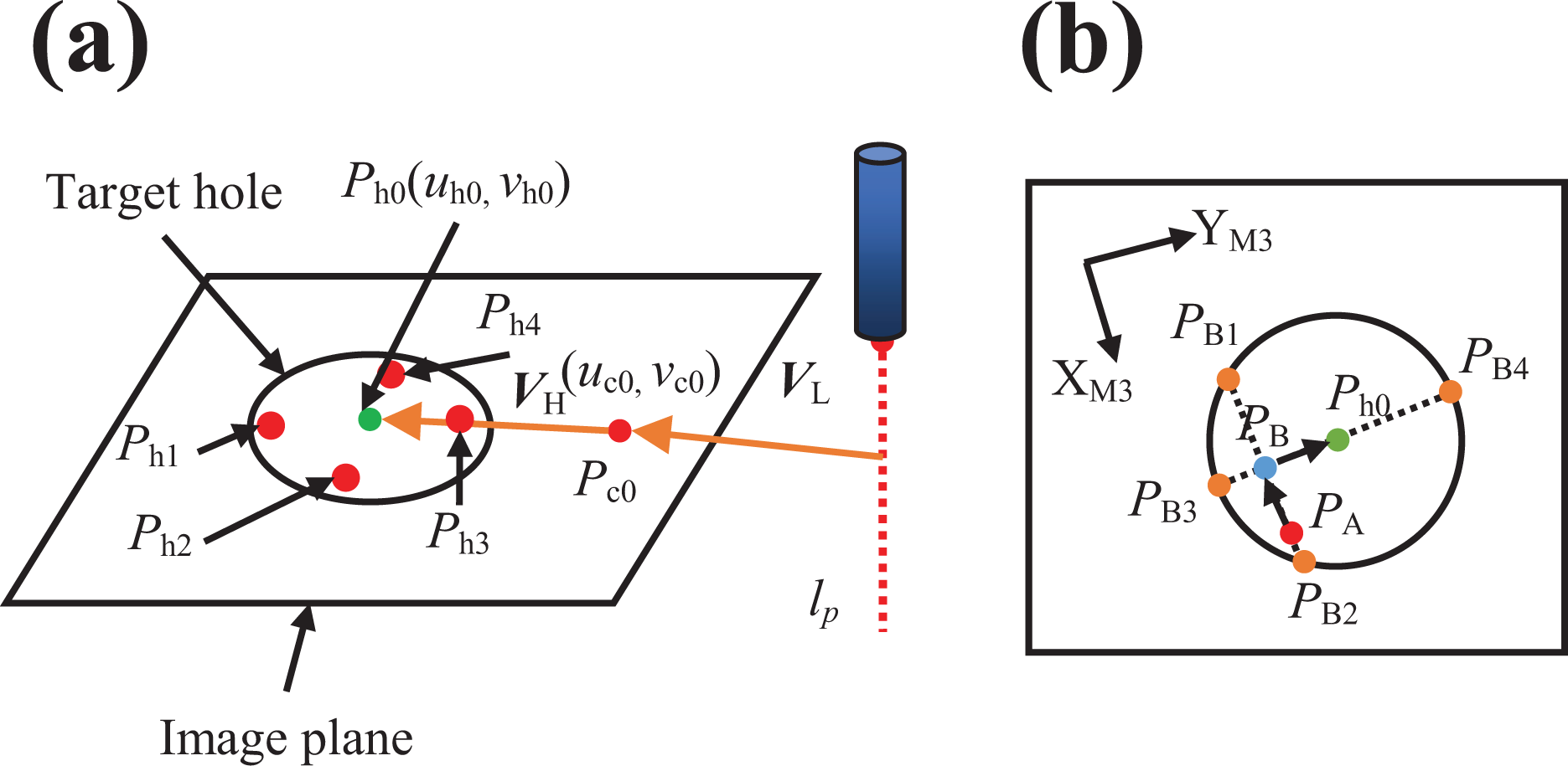
Sketch of laser range sensor alignment, (a) coarse alignment and (b) fine alignment.
Laser range sensor alignment includes coarse and fine alignment. In coarse alignment stage, the camera is firstly moved for making
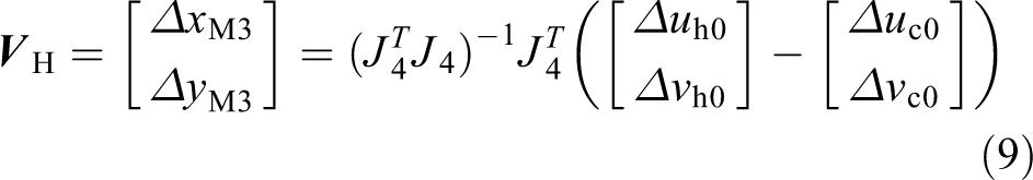
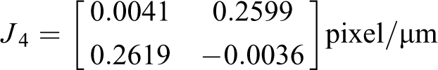
where J
4 represents the transformation from incremental translation of feature points along with
The altitudes at
Dispensing control
The dispensing control system is shown in Figure 11, which is based on the time–pressure model described in the fourth section. A PI controller is used for the dispensing control.

where

The diagram of dispensing control.
The fluid glue altitude increment
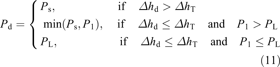

where
If the altitude difference
Dual dispensing strategy
Generally, the fluid glue should wait a little time to become stable after being dispensed into the target hole from the pipe. The fluid glue will spread from the central region to the edge region owing to gravity.
Figure 12(a) shows the pipe aligns with the target hole. In rapid dispensing stage, the pipe is moved along

Sketch of pipe movement strategies in one-time dispensing procedure. (a) The pipe aligns with the target hole, (b) the pipe movement in one hole, and (c) and (d) the movement of pipe and laser range sensor in the dual dispensing strategy.
A dual dispensing strategy with high efficiency is proposed. The fluid glue is dispensed into two holes simultaneously. Firstly, fluid glue is dispensed into two holes sequentially by using the rapid dispensing method. Then dual dispensing strategy works. As shown in Figure 12(c), the laser range sensor measures the altitude of the fluid glue in target holes 1 and 2 sequentially. The corresponding positions are saved for fast movement from one hole to the other hole. Then, the pipe is moved to align with target hole 1. According to the aforementioned dispensing control strategies, fluid glue is dispensed into target hole 1. Then, the pipe is moved to align with target hole 2 and laser range sensor is moved to align with target hole 1, as shown in Figure 12(d). The pipe and laser range sensor obey this moving strategy until the fluid glue altitude of any one hole reaches expected altitude. The pipe movement in one hole is shown in Figure 12(b). The pipe is moved along
Experiments and results
Experiment system
An experiment system was established according to the scheme given in the second section, as shown in Figure 13. In this experiment system, there are three microscopic cameras with Baumer TXG50. All the three cameras are equipped with a Navitar zoom lens with magnification 0.7–4.5×, which capture images 15 f/s with an image size of 2448 × 2050 in pixel. The adjusting platform is composed of KOHZU PK544PMB for rotation around

Experimental system.
The image Jacobian matrices J
1, J
2, J
3, and J
4 and the force transformation matrix


Automatic assembly experiments
The features were extracted as described in the third section. The parameters of PI controllers were set as follows:
The automatic assembly process includes orientation alignment, position alignment, and insertion process with the methods discussed in the third section. The component A was aligned with the component B in orientation and position with high precision. The alignment errors in one assembly experiment are shown in Figure 14. Figure 15 shows the images captured by three cameras before alignment, after alignment, and after insertion. The final orientation errors around
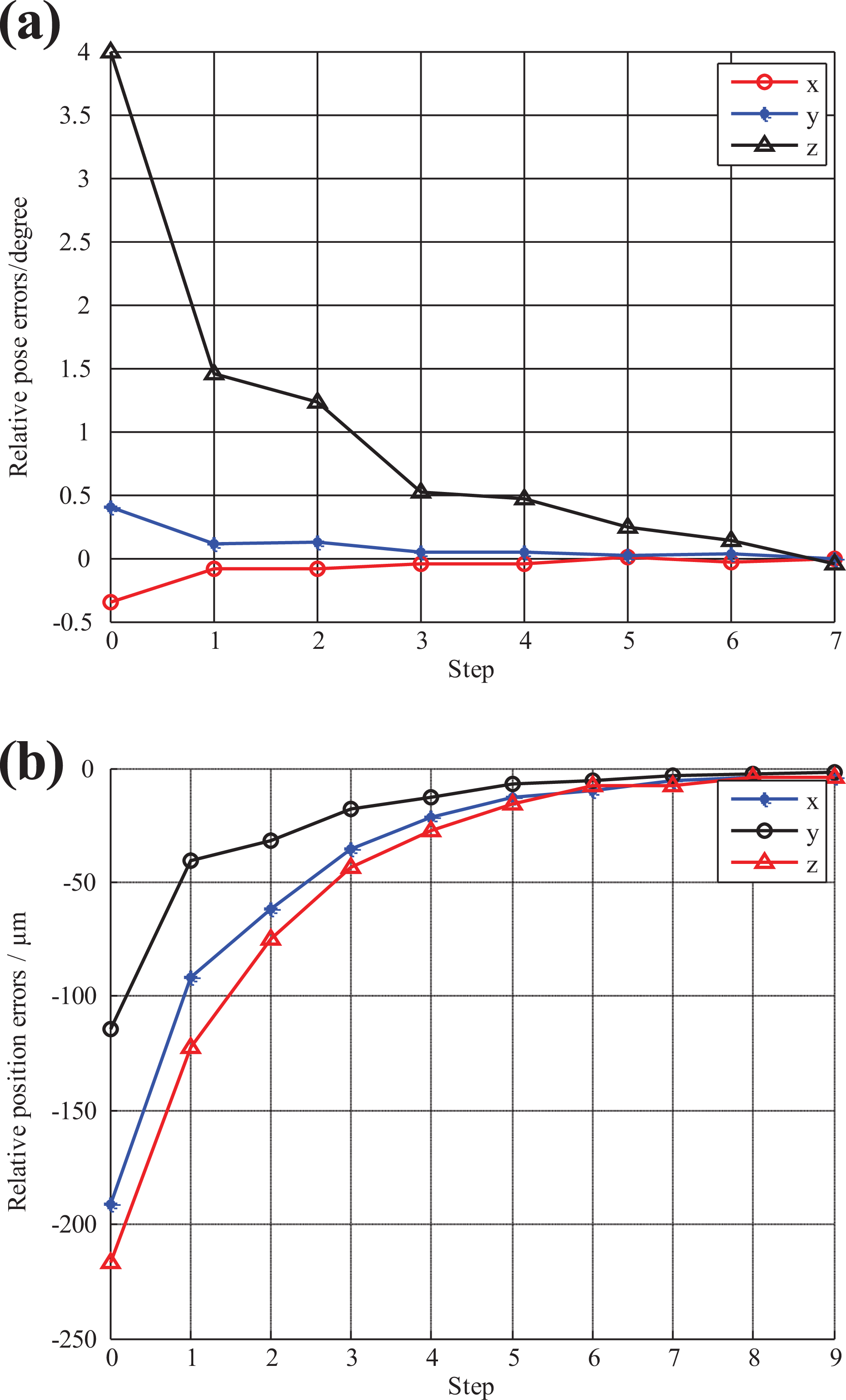
The errors in (a) orientation alignment and (b) position alignment.

Images captured by (a1) microscopic camera 1, (b1) microscopic camera 2, (c1) microscopic camera 3 before alignment, (a2) microscopic camera 1, (b2) microscopic camera 2, (c2) microscopic camera 3 after alignment, (a3) microscopic camera 1, (b3) microscopic camera 2, and (c3) microscopic camera 3 after insertion.
Dispensing experiments
The fluid glue should be dispensed into all 16 holes and the results in one dispensing experiment are given as follows. According to the fast dispensing strategy described in the fourth section, two holes are dispensed in one dispensing batch.
The parameters of dispensing control are given as follows:
After the rapid dispensing stage, the relative altitude error of fluid glue in the two holes became 33.5 and 37.8 µm, respectively. The relative altitude errors during precision dispensing stage are given in Figure 16. The parameters

Relative altitude errors in precision dispensing stage.

Final relative altitude errors of 16 holes.

Comparative experiments
The orientation measurement method in the study by Liu et al.
6
is selected as the comparative method. In the method by Liu et al.,
6
the orientation of component A is measured by extracting the lower surface edge in images. When the component A is rotated around

where
The method in this article can directly measure the normal vector of component A in

where

The edge lines detected results by using the method by Liu et al. 6 (a) The result in camera 2, (b) the amplified image of (a), (c) the result in camera 3, and (d) the amplified image of (c).
Comparative experiment results (in degrees).

The average angle errors around
Conclusion
The main contribution of this work is the high precision alignment and efficient dispensing approaches for millimeter objects based on microscopic vision and laser range sensor. An orientation measurement method based on laser range sensor is developed to measure the norm vector of upper surface. Then, it is converted to the increments on the images captured by the two side cameras via image Jacobian matrixes. The measure accuracy is satisfactory even if the normal vector of upper surface of thin component is not perpendicular to the optical axis of side camera. Two components are aligned in orientation and position with high precision according to the measurement results. After assembling the two components, fluid glue dispensing is used to bond them. For keeping the two components stable, the volume of fluid glue dispensed into the 16 holes should be controlled precisely. Primarily, a high precision searching-based method is proposed to align the laser range sensor and target hole. Furthermore, in order to keep the fluid glue reliability, the dispensing process of 16 holes should be finished in a limited time which means the efficiency is quite important. A dual dispensing strategy with high efficiency is developed, which utilizes the waiting time for the fluid glue spreading in a hole to dispense in another hole. The efficiency can be improved about 37%. Experimental results demonstrate the effectiveness of the proposed methods.
In the future, we will focus on intelligent control methods in assembly and dispensing process.
Footnotes
Declaration of conflicting interests
The author(s) declared no potential conflicts of interest with respect to the research, authorship, and/or publication of this article.
Funding
The author(s) disclosed receipt of the following financial support for the research, authorship, and/or publication of this article: This work was supported by Science Challenge Project, NO.TZ2018006-0204, National Natural Science Foundation of China (61733004, 61673383, 61873266) and National Key R&D Program of China, NO.2018YFD0400902.