
Abstract
Walking machines have proved to be an important invention as they do not require any prepared surface, making them ideal for applications involving unexplored environments. They are equipped with a large number of actuators and sensors to achieve a robust locomotion; thus, a systematic approach to designing their control system is required. This article presents a functional control structure based on the logic-labelled finite state automaton approach developed for walking machines. A general control structure is presented and a hexapod robot is used to verify the practicability of the design.
Introduction
One of the most important outcomes of biological evolution is the ability to walk since it does not require any prepared surface. Traditional mobile robots mostly use wheels which work well with only flat surfaces. For robots to be able to navigate in unknown environments, it is imperative for them to imitate the walking behaviour of biological species. Consequently, robotics has evolved to address this issue by coming up with the walking machines. The multi-legged walking machines do not require all appendages to be touching the ground making them more suitable for utilisation in uneven environments.
Many types of walking machines have been developed. Bipedal robots imitate human beings, however, for a legged robot to be statically stable, it should comprise three or more legs. For this reason, quadrupeds and hexapods are the most common walking machines. These robots have a large number of actuators and many sensors for their locomotion. It is evident due to their complex nature that a systematic approach for designing the control system of such machines is crucial for its closed-loop performance.
Mechanical design and motion generation for the multi-legged walking machines have been the main focus of researchers. 1 –4 Although these are important aspects for the development of robots, it should be noted that the control system realisation problems have been a hurdle in their successful practical implementations.
By studying insect locomotion, it can be seen that they have different gaits and switch between them based on feedback coming from sensory neurons. Similar behaviour can be associated with walking machines. The robot should be able to alter its gait based on sensory feedback, adapting to the changing terrain. The gaits can be interpreted as different states of the robot locomotion, making it ideal for representation as a finite state machine (FSM).
The purpose of this research is to elaborate and test the functional structure of a control system using the logic-labelled finite state machines (LLFSMs) approach. The functional structure under consideration is being designed for a walking machine performing exploration tasks. The main focus is on using a systematic approach to create a system having real-time capabilities.
This article is structured as follows: the state of the art related to control system design is presented first with focus on walking machines, followed by motivation of the work done and its context. The overall developed control structure is discussed next. The next sections describe the various FSMs developed, namely the global navigation and the local navigation FSMs along with the data repositories illustrating the whiteboard concept. Next, we demonstrate the utility of the concept through a real-time implementation using dedicated simulation tools. We illustrate the essential cases and explain the corresponding actions of the designed controller. The final section emphasizes key findings with concluding remarks.
State of the art
The control system of any robot is a crucial component for its success. It dictates how the robot behaves. Usually robots exhibit reactive behaviour. Thus, sensors play an important role for optimal closed-loop control.
Typically, there are many sensors present in the system, acting as the input for the control system. A global positioning system (GPS) allows the evaluation of the starting position of the walking machine, whereas a compass gives the heading direction (yaw angle) towards the goal. For detection of terrain conditions, the walking machine is equipped with inclinometers which calculate the roll-and-pitch angles. Proximity sensors allow detection of obstacles, digital encoders give feedback on the position of the leg joints, while the leg ends are equipped with contact or force sensors as well. The terrain properties govern the gait of the walking machine. The control system must be capable of handling all the gaits and the sequence of the leg transfer motion from one periodic gait to another.
One of the most essential principles in designing a modern software architecture is modularity. The main system is divided into several smaller modules, each responsible for a specific task, thus, allowing for a system developed for one robot to be used for another simply by replacing a module. The arrangement of these modules along with how they interact determines the control structure of the robot. Although there are many methods to arrange these modules such as the subsumption architecture, 5,6 the hierarchical approach 7 –14 remains the most popular for walking machines.
Real-time systems need to react to external events within specific time constraints. Thus, the correctness of such systems depends not only on producing the adequate response but also on temporal factors, that is, when the response is produced. The real-time operating system (RTOS) 15 is usually incorporated into the embedded system with regard to robotic applications. Over the years, many RTOS have been developed such as RTAI, 16 QNX, 17 and VxWorks. 16 QNX is considered the best RTOS for complex walking machines’ control systems as it offers fast and predictable performance and has an excellent architecture for implementing a robust distributed system.
Although many robotic control systems 18 –21 have been developed with real-time capabilities for walking machines, the systematic FSM methods are not yet applied. FSM, a tool in model-driven engineering, is a computational model based on a system a finite number of states. An FSM is represented as a directed arc with nodes representing the system states and the arrows representing the state transitions. At any given time, only one state can be active. The machine can transition to another state based on logical statements that need to be proved by an inference engine. The LLFSM approach offers a reliable, robust and quicker design solution. It is a promising recent tool that has demonstrated to be an effective technology for modelling robotic control systems as demonstrated by Estivill-Castro et al. 22 and Figat et al. 23
Motivation
The presented work is motivated by studies done by Estivill-Castro and Hexel for designing fast reactive systems 24 in which the FSM approach was successfully applied to timing-critical systems and by Zielinska and Heng on the development of real-time control systems for quadrupeds and a team of autonomous hexapods. 14,19
In the latter example, the authors utilized the concept of multi-processing, using semaphores for synchronisation, and the QNX RTOS (C language) ‘send’, ‘receive’ and ‘reply’ commands. When sending the message (‘send’ command), a response was always required, resulting in a synchronous, sequential realisation of process actions (reflected in the sequence of the program commands), that is, after dispatching the ‘send’ command, the sending process is suspended. The associated message data reach the receiving process (through its ‘receive’ command), which then responds with a ‘reply’ command (potentially containing response data resulting from the receiver’s processing between ‘receive’ and ‘reply’). Only once the ‘reply’ command is received, will the sender process continue. Analogically, the receiving process will be suspended on the ‘receive’ command until message/data are provided by the sender through its ‘send’ command. This combination of blocking ‘send’ and ‘receive’ operations is often referred to as a rendezvous and ensures tight synchronisation between sender and receiver.
With this mechanism, timely data transfer without suspending the global navigation and local navigation processes was possible but with an intermediary process acting as a data deposit box. However, this approach does not scale to complex systems, and even for simple architectures, the applied communication concept needs careful data handling and messaging 19 with clear indication which process is the receiver and which one is the sender. Of course, the senders to some processes can be receivers from another ones. The tested system worked well allowing to implement complex behaviours – it was easy to add or replace the walking gaits or to modify the navigation strategy, however, the communication channels (send, receive, and reply) between processes limit the possibility of global rearrangement of process communication. To overcome the limits and complexities of such data-driven coordination of processes, we decided to adapt the FSM-based approach that does not have this limitation and has successfully been tested in the software systems in the first example.
Acknowledging the system-level impact of communication bounds, 19 we apply the whiteboard concept that defines the semantics of communication only in terms of data. With this approach, ‘everybody’ can access any data in the whiteboard repository and (theoretically) at any time. However, to avoid any complexity resulting from explicit synchronisation, we need implicit synchronisation for the proper coordination of system actions which is provided by the deterministic timing of a scheduled arrangement of FSMs. 24 The system actions previously implemented and tested using the data-driven approach were transferred to FSM structures and implemented using the MiEditLLFSM modelling tool.
Our main contribution is the walking machines’ scalable control system design concept using a deterministically scheduled FSM concept (equivalent in structural composability to a multi-threaded architecture, but akin in complexity to a single-threaded system) with whiteboard communicated data repositories. The concept is free of communication bounds, however, all the state realisations must be carefully designed. The present article delivers the general concept of control system development focusing on walking machines. For the demonstration of the system work, the navigation task with obstacle avoidance was implemented. That choice allows us to compare the system behaviour with previously developed control and navigation system for the team of walking machines.
Control system structure
The general decomposition of the control system and the tasks assignment was proposed considering our previous experience with the design of QNX-based motion-control system for a team of autonomous walking machines. The concept was proved as being universal and efficient in the tested complex real-time scenarios. 19,20 For implementing the system functions in this work, we decided to use the FSM approach instead of event-driven design applied previously. The main advantage of using FSM is seen in its universality (application is not limited to RTOS) and efficiency in system prototyping as it is illustrated.
The developed control structure divides the overall system into smaller subsystems which are arranged in a hierarchical (top-down) structure. Such a hierarchical control scheme that was chosen as the developed control structure is not for a specific walking machine but can be used with any walking machine, regardless of the number of actuators and sensors attached to it. A subsystem can be replaced by another one as suited for the walking machine. This incorporates modularity into the system. The modular flexibility of the control structure allows it to be easily distributed over a network of microprocessors.
The general communication method is such: the highest level process sends the task demand to the level below (middle level), which in turn sends its demand to the level below it. All processes are self-reliant and equipped with tools to meet the demand. However, only when the demand cannot be met, the upper subsystem (the level directly above the level which is not able to fulfil the demand) is informed and a new demand is requested. Figure 1 illustrates the detailed breakdown of the control system processes. The main tasks associated with each process are also mentioned. Each process in the control structure is treated as a separate finite state automaton.

Detailed overview of the subsystems.
Since the activities of the sensory and user interface subsystems are simple in comparison with the global and local navigation subsystems, for brevity only the latter is discussed here. Inverse kinematics of walking machines is a widely researched area, however, it is specific to each walking machine. Therefore, the actuation control subsystem responsible for the inverse kinematics is also not discussed here.
Global navigation FSM
The global navigation automaton is the highest level subsystem in the control structure and is responsible for route generation. It interacts with the user interface automaton, receiving target waypoints and requesting further instructions in case of a locked path. Moreover, the global navigation process monitors the mission, calculating the heading error and evaluating the position errors. This information is deposited on the status repository which is subsequently used by the local navigation subsystem. Figure 2 shows the activities carried out by the global navigation subsystem as described by an LLFSM.

Activities of the global navigation subsystem represented by an FSM. The circles are marking the states, the branches are marking the events, and the green boxes are marking the accessed/deposited data in the whiteboard. The state transitions are triggered by data taken from the whiteboard. For whiteboard connection, the arrows are indicating the data flow (one way or two ways). FSM: finite state machine.
Each state of the global navigation automaton is described below:
Local navigation FSM
The local navigation subsystem is the middle-level functional process in the hierarchy. It is responsible for detailed path navigation and gait selection. It uses information from the proximity sensors to produce a collision free path for the robot, fulfilling the route demand received from the global navigation subsystem. The information from the inclinometers is used to define the type of gait motion.
The navigation algorithm defines the body trajectory. This demand is sent to the lowest level in the hierarchy, that is, actuation control subsystem which generates the motor commands. Based on the body trajectory, the control system should also be able to evaluate the new position of the robot on its own since the GPS data are unreliable. Figure 3 shows the activities carried out by the local navigation subsystem as described by an LLFSM.

Activities of the local navigation subsystem represented by an FSM. The state transitions triggered by sensed conditions are adequately labelled, for example,
The states of the local navigation automaton are:
The walking machine’s locomotion is characterized by a series of leg displacements known as a gait. There are many possible gaits, however, for the purpose of experimentation, only two periodic gaits are incorporated in the control system, namely the tripod gait and the wave gait. The local navigation subsystem is also responsible for the selection of these gaits. A two-tier definition of the behaviours is used. The upper level (the local navigation FSM as shown in Figure 3) is an FSM which switches between one and more of these behaviours. The lower layer governs which type of gait to use. This two-tier description follows the concept of hierarchical FSMs. The generic template of the sub-behavioural FSM modelling the behaviours of the local navigation subsystem is demonstrated in Figure 4. This arrangement of hierarchical FSMs is used with the

Activities of the motion behaviours represented by an FSM. FSM: finite state machine.
The various states of the sub-behavioural FSM for each motion state of the local navigation subsystem are described below:
State activities
The state activities represent two levels of abstraction: The states providing and serving the walking machine motion. The machine representing the overall system states.
The states denoted with
The detailed realisation of actions serving the system depends on the physical system, for example, on the processor architecture, available indicators of hardware components status, on the level and availability of fault information and the like. Hardware and software dependent examples are shown by Zielinska and Heng 19 for another concept of control system development. In simulations, the system serving actions are naturally much simpler. Suffice it that here we summarized the global and local navigation FSM state activities.
OnEntry and OnExit conditions (denoted by
Data repositories
The interprocess communication is done through a central database holding all shared data. There are several data repositories represented in this central database, namely the sensor repository (
Description of data contained in the sensor repository (

Description of data contained in the waypoint repository (

Description of data contained in the demand repository (

Description of data contained in the status repository (

Implementation
The FSMs described above were implemented using the MiEditLLFSM modelling tool. 24 This tool was developed for the IT industry. Therefore, it can be used for modelling the activities of a robotic control system. The actions of the individual states were defined using C++ code. When all the activities of the individual FSMs were specified, the executable C++ code was automatically generated by the tool. The execution of the FSMs was determined by a scheduler. Concurrency is maintained through a static schedule that guarantees atomicity by ensuring that only one step of the FSMs is executed in each time slot.
Selection of FSM implementation method
Event-driven approaches in which the transitions are labelled by events are more popular for modelling the actions of an FSM. Over the years, many frameworks 27 –29 have been developed for the implementation of such models. However, the event-driven-based models require implementation as a set of concurrent threads which communicate with each other. This multi-threaded approach increases the load on the system as a supplementary process must manage the synchronisation of the threads and make sure there is no deadlock or thread starvation. Moreover, the idealised model of physical chance events, ordered on an infinitely dense time line can only be approximated in software, resulting in nondeterministic memory usage and timing, unsuitable for the requirements of reactive real-time systems. 30 A further drawback of the event-driven models is that the verification process may result in a combinational explosion as all combinations of the FSM states need to be correct. This considerably compromises the formal verification of the models both in the time domain and the value domain.
To resolve these issues, alternative approaches 24,31 have been proposed. Such approaches support single-threaded execution of multiple FSMs. MiEditLLFSM tool is one of the frameworks that use this approach. It follows the approach of Harel’s statecharts 32 and defines the behaviours as a mathematical model. 33 In contrast to the asynchronous event-driven frameworks, this tool ensures synchronous FSMs. The MiEditLLFSM tool will be used to model the behaviour of the walking machines as it provides all the necessary tools for modelling.
MiEditLLFSM modelling tool
The MiEditLLFSM tool has been developed by MiPal. It represents an FSM as a graph, the states as nodes and transitions as arcs. The nodes are connected to each other by directed arcs. The arcs are labelled by Boolean expressions. This is in contrast to the event-driven approach where the arcs are labelled by events. The generality is not compromised as the Boolean expressions can also represent an event occurrence.
Each state of an FSM is attributed with three sections
34
which are described below: An OnEntry section contains the action that needs to be carried out when the system enters that state. An OnExit section contains the action that is executed when the system leaves the state and transition to another state. An Internal section contains the actions that are carried out when no transition is triggered. Unlike the other two sections which are executed only once, these actions are executed repeatedly until a transition condition becomes true.
Whenever a transition is enabled, the FSM switches to the next state and executes the OnEntry section of the new state. Each section only executes a single action. Multiple FSMs need to be executed simultaneously to ensure real-time capability in the system. The MiEditLLFSM scheduler ensures that at each time slice, one step of the FSM is executed satisfying concurrency in the system.
Communication via whiteboard
The whiteboard 35 is a structured global database which mimics the blackboard architecture. 36 It stores all the variables contained in the FSMs (data represented in the data repositories described previously) and allows access to all FSMs running on the system as represented in Figure 5. However, at any time only one FSM should have access to the whiteboard to provide lock-free atomicity. The FSM scheduler ensures this.

Communication between FSMs using the whiteboard. FSM: finite state machine.
There can be three types of variables in the system: Local variables are available only within an FSM. Internal variables are shared among the various FSMs in the system. External variables are outside the system such as the data from the sensors.
Whenever a section of the current state executes, it first reads the whiteboard and makes local copies of the whiteboard variables. This is required so that all data being used by the action or transition function are recent.
Real-time implementation of concurrent FSMs
During the implementation, all three sections of the state were used. The OnEntry section associated with each state was used to setup the state variables. The OnExit section was used for the clean-up code. All the cyclic actions were implemented in the Internal section. Figure 6 shows a section of the implementation of the local navigation FSM described earlier. Only a particular section of the FSM (the section pertaining to

Implementation of local navigation FSM showing the OnEntry, OnExit and Internal sections of the states. Only the state transitions and code relating to state
All FSMs described previously are executed simultaneously using a parallel programming structure. Each FSM is executed as a single-threaded process. The concurrent FSMs are arranged in a round-robin structure following the guidelines provided in the study by Estivill-Castro and Hexel. 24 This implies that each FSM gets the processor’s resources for a ringlet (a pass over the cycle) execution. Once a ringlet completes its execution, the next FSM in the arrangement gets the processor’s resources. This execution is governed by an execution token. When an FSM enters a suspended state, the execution token is passed to the next FSM in the arrangement.
During a ringlet, a local copy of the variables is made before execution of any section of the state. This ensures that the data within an FSM are current and that no other concurrent FSM modifies the data during the state action execution, barring the need for semaphores and mutexes. This avoids concurrency issues and results in predictable timing required for real-time operation.
Simulation experiments
To verify the functionality of the proposed robot control system, the logic-labelled finite-state automaton-based control system was simulated using the Virtual Robot Experimentation Platform (V-REP) simulator. 37 V-REP is a cross-platform simulator allowing the creation of scalable, portable and easy to maintain models and scenes. Four different physics simulators (Bullet, Newton, ODE and Vortex) allow the simulation of soft and rigid body dynamics along with collision detection. Diverse selection of powerful and realistic sensors such as proximity and vision sensors is also available within the simulator. The ability to run scripts using a remote application programming interface is beneficial as it allows a convenient mechanism to control the simulation using the MiEditLLFSM tool.
The simulator is responsible not only for modelling the geometry of the environment and its dynamics but also responsible for modelling the activities of the robotic subsystems, that is, providing the data to the sensory modules, for example, the presence of obstacles in the robot’s trajectory; reacting to commands received from the actuation control subsystem, for example, movement of leg-ends based on the trajectory received.
The simulation environment consisted of a set of obstacles of varying sizes randomly placed in an open space as represented in Figure 7. Inclined surfaces were also placed in the robot’s path. It should be noted that the big walls seen on either side of the robot are not physical objects but rather define the corridor in which the robot must limit its motion. The corridor is determined by the start and goal positions and changes with each waypoint. A 3-m corridor width was chosen for the simulation experiments.

Simulation of the robot navigating in the unknown environment.
A built-in model of the ant hexapod robot was used. The ant has a rectangular body architecture and each leg has three degrees of freedom. GPS, compass and inclinometers were attached to the robot model to provide robot pose as feedback to the control system. Six proximity sensors were also attached to the hexapod with properly selected field of views as represented in Figure 8. Since the inverse kinematics of the leg trajectories is not the focus of this research, the IK mode provided with the built-in model was utilized for simplicity. Interested readers can visit the V-REP website 37 for details on the IK mode.

Arrangement and field of view of the proximity sensors.
Various scenarios were simulated for the robot. The robot was made to navigate between a set of user-defined waypoints. The robot searches for a path between each waypoints. Ideally, the robot tries to follow the shortest path between the start and the goal positions, that is, straight line trajectory. When an obstacle blocks the desired path, the robot tries to navigate around the object. If a path exists around the obstacle, the robot continues its motion towards the target waypoint. However, in case no path exists within the robot workspace constraints, then a signal is generated and the situation is communicated to the user, while the robot awaits further instructions. This limited knowledge path search followed by the robot is similar to that of a bug algorithm. 38 Figure 9 represents examples of trajectories taken by the robot during the simulation experiments. The experiments were designed referring to the real-world scenarios that were tested previously using a different control system but based on the same navigation principles. 20

Robot trajectories in various tested scenarios. (a) Robot demonstrating obstacle avoidance. (b) Robot trajectory over multiple user-defined waypoints. (c) Path blocked behaviour. (d) Gait switch behaviour based on surface inclination
Figure 9(a) shows the robot’s obstacle avoidance behaviour. From the start position to point 1, the robot walks using the forward gait, being in state
A typical mission for the walking machine involves a set of target waypoints. Figure 9(b) illustrates one such mission. Three waypoints are sent by the remote user to the robot. The robot moves towards the first waypoint avoiding the obstacle present in its path. The state transitions are similar to the ones explained for Figure 9(a). Once the first waypoint is reached,
Similarly, Figure 9(c) shows the robot behaviour upon encountering a blocked path. The second waypoint in the mission is not reachable since it is blocked by an obstacle. At the point when the robot cannot find a path around the obstacle from either the left or right side,
Figure 9(d) illustrates the transition from tripod to wave gait when the surface is at an inclination. The inclined surface is marked by the orange rectangle. The robot transfers the gait to wave gait when entering the inclination according to the state transition diagram in Figure 4. Small discrepancies between the desired and realised trajectory can be noticed but they are corrected before reaching the target point (see state
In ideal cases, a smooth trajectory is usually preferred. In contrast, the robot can be seen exhibiting a slightly erratic trajectory. This is due to the fact that a small tolerance of ±5° has been included in the robot heading direction error. Increasing the tolerance results in a smoother robot trajectory. However, increasing the tolerance too much causes a more erratic behaviour near the goal position. Thus, a compromise needs to be made.
A position error of ±5 cm was observed for each waypoint during the simulation experiments. This error is due to the fact that the hexapod can only move at discrete distances corresponding to its stride length.
Comparative study
Zielinski et al. 39 offer deep insight to the methodology of control systems design with broad literature review. The authors claim ‘Usually, architectures are presented by informal text descriptions supplemented by block diagrams, with varying level of details’; this makes the comparisons impossible. Very few publications 40 –42 are tackling the problem of effective control systems for multi-legged walking machines; moreover, the descriptions are in general hardware and case oriented. On the other hand, due to the omnidirectionality, availability of many gaits and the need of locomotion adaptation to the terrain conditions, the control and navigation is rather complex.
When developing the architecture and working principles of the control system, several aspects are crucial. To this belongs: the robustness of the system to faults; scalability and composability; the system openness to modifications and additions; establishing correctness and efficiency; global accessibility of the most recent system data.
As already mentioned, the whiteboard concept allows to access a snapshot of the most recent data. The lack of communication bounds makes the system open to enhancements and modifications; moreover, even the previously neglected reactions to the system faults can be easily modelled and added. The correctness of the system must be guaranteed through an error-free implementation of subsystem states and interactions. The FSM-based approach has one more crucial advantage here; individual submachines as well as system actions can be easily tested by simulations and the same action structures can be used for developing the real system. This is a natural consequence of the independence of actions and data. The data can be delivered (and deposited) either by a simulator or by a real hardware. From the point of view of the system actions, this makes no difference, enabling testing of subsystems in isolation as well as in collaboration.
The disadvantage of the approach is the need for careful description of the activities (examples in Figures 2 and 3) without any mistakes in the definition of the accessed data and the state transitions. However, the danger of logic errors is rather the general drawback of developing complex control systems. As already mentioned, the simulation test is the remedy here. The tested part of the system can be directly moved to the real robot, and only the required hardware interfaces need to be added along with testing of system reaction to hardware faults.
Conclusion
A logic-labelled finite state automaton approach was presented to design a functional structure of a walking machine’s control system. The control system was decomposed into three distinct functional subsystems arranged in a hierarchical structure, where each subsystem’s activities were defined by an LLFSM.
The MiEditLLFSM tool, 24 an editor for LLFSMs, was used to model the behaviour of the FSMs. The tool allowed executable high-level behaviour models to be created facilitating both the modelling of the activities of the control system and the automatic code generation. The tool also manages the task scheduling for all the FSMs using a single sequential scheduler. Communication between the various FSMs was done using the whiteboard.
Generally, FSM-based approaches use an asynchronous event-driven multi-threaded model. However, such systems require a supplementary process to manage the synchronisation of the threads which increases the load on the processor. More importantly, multi-threaded, event-based models cannot guarantee predictability and are harder to verify. This makes them unsuitable for real-time robotic control systems. Thus, a single-threaded FSM execution approach was used to implement the FSMs.
The developed control system makes use of shared variables/memory. A problem with such an approach is that when one process is reading the shared memory, another process may alter the contents of that variable. This generally requires the use of mutexes and semaphores to protect the data. In contrast, a single sequential scheduler is used in the MiEditLLFSM tool which ensures that in a single time slice, only one FSM accesses the whiteboard/shared memory. Thus, there is no contention among the FSM processes during their execution.
The proposed control system allows for a remote operator to set waypoints for the walking machine. The path cannot be pre-planned and is generated in real time based on sensory information. The navigation algorithm implemented is a limited knowledge path planner.
The FSM-based approach was tested on a V-REP simulation which used a hexapod robot as an example. Various sensors needed for the control system to function correctly were incorporated in the physical structure of the hexapod. The robot was made to navigate in different environments. Obstacles were placed in the robots path to verify the obstacle avoidance algorithm.
As it was illustrated, the LLFSMs allowed to derive the architecture of complex control system in a clear and systematic way. Moreover, the system developed and tested in simulation can be easily applied in real-life applications, just by adding the hardware interfaces.
The work done provides a basis for designing robotic control systems based on the logic-labelled finite state automaton approach. As a next step, the implementation of the proposed approach will be extended to control an actual hexapod.
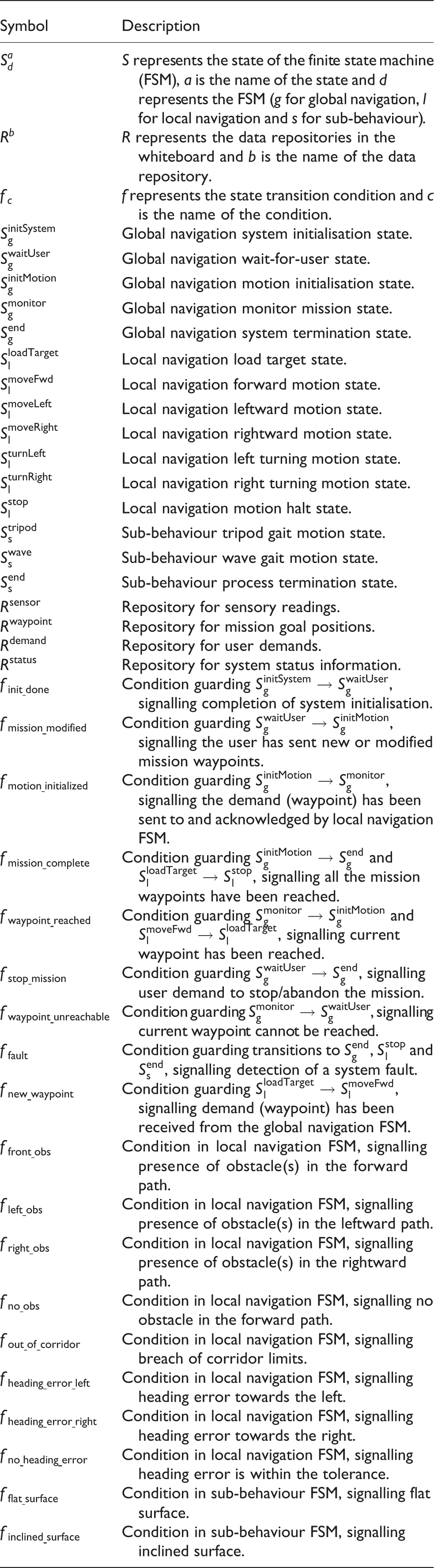
Nomenclature
Footnotes
Acknowledgements
The authors would like to thank the support of European Master in Advanced Robotics plus (EMARO+) and Pacific Atlantic Network for Technical Higher Education and Research (PANTHER) programs.
Declaration of conflicting interests
The author(s) declared no potential conflicts of interest with respect to the research, authorship and/or publication of this article.
Funding
The author(s) received no financial support for the research, authorship and/or publication of this article.