
Abstract
This article presents a novel passivity-based adaptive delay compensation scheme for cancelling actuator dynamics in real-time hybrid testing. This scheme uses the energy added to the system by actuation hardware, to quantify a variable delay, which is subsequently used for delay compensation. It offers the advantage of correcting for tracking errors and instability in hybrid tests and can be implemented without any information of the actuator’s dynamics. Thus, it offers an advantage over most conventional actuator dynamics mitigation schemes which require an accurate model of the actuator prior to testing. Experimental results compare the performance of passivity-based adaptive delay compensation with that of a state-of-the-art adaptive delay compensation scheme based on position. It was found that passivity-based adaptive delay compensation continuously updates the delay estimate while the position-based scheme only updates the delay when the system crosses zero. The performance of both schemes was found to be similar for sinusoidal inputs, mitigating phase lags of up to 35.6° at 10 Hz in the hybrid system tested. Passivity-based adaptive delay compensation requires no extra hardware as it can be run on the same hardware used to drive the actuator, enabling an affordable solution applicable to a wide range of hybrid tests.
Keywords
Introduction
Real-time hybrid testing involves separating systems into numerical and physical substructures which are tested in parallel with actuators and force sensors used for real-time data transfer. Actuator delay is a notable problem in hybrid testing as it results in tracking errors and can lead to instability. Delay compensation has long since been a tool used to supress actuator dynamics in hybrid tests. An early example of a delay compensator that saw widespread success in hybrid testing is presented in the work of Horiuchi et al. 1 The scheme is based on a forward predictive algorithm to predict the actuator response ahead of the time delay based on its past response. However, one of its limitations is that it can only correct for delays which are integer multiples of the timestep. More forward predictive schemes have been developed by several authors over the years such as those seen in the work of Darby et al. 2 and Ahmadizadeh et al. 3 Tang et al. 4 present a review of such techniques and conclude that performance gains are mostly seen within a narrow frequency band as amplitude ratio and phase errors are seen at high frequencies.
Recent applications of novel compensation schemes in hybrid testing are seen in the work of Bartl et al. 5 which assess the performance of an adaptive feed-forward filter in delay compensation of hybrid tests. A recursive least squares algorithm is used to minimize the gap error for stable hybrid tests. The method is shown to be effective in reducing delay and improving tracking in nonlinear real-time hybrid tests; however, the scheme in unable to restore stability in hybrid tests made unstable by actuator delay. On the other hand, Peiris et al. 6 use a passivity-based damping controller in real-time hybrid tests to provide a solution that restores stability in real-time hybrid tests made unstable by actuator friction and a stiff physical substructure. However, the scheme is unable to mitigate tracking error. Therefore, passivity-based adaptive delay compensation (PBADC) adds great value to hybrid testing as it offers both stability and tracking improvements.
The state of the art in delay compensators for hybrid tests mostly rely on fixed delay models. However, model delay compensators are often inaccurate, particularly in hybrid tests where actuator behaviour is nonlinear and/or affected by the physical substructure. PBADC offers a compensation strategy where the actuator delay estimate is online and dynamic, enabling adaptive compensation for nonlinear hybrid tests, as well as linear hybrid tests experiencing variable delays in the actuator. A significant benefit offered by this scheme is that it requires no information of the hybrid system or actuation hardware prior to testing. Therefore, the scheme can be highly effective in many classes of systems such as those with discontinuous nonlinearity, displacement-dependant nonlinearity, and friction nonlinearity as found in this work.
Methodology
In a hybrid test excited at the numerical substructure, displacements calculated in the virtual subsystem of the hybrid test are applied to the physical substructure via actuators. Load cells are often used to measure forces at the physical substructure which are fed back to the numerical substructure to close the loop of the hybrid test. There is a calculated energy flow from the numerical substructure to the physical substructure, and an actual energy flow from the actuator to the physical substructure, and these are in general different due to actuator tracking errors. The energy flowing from the actuator may exceed that intended by the numerical substructure. This surplus of energy leads to tracking errors and potential instability in hybrid tests.
The proposed PBADC scheme is based on regulating the energy flow in the hybrid test. The existence of a delay in the actuator’s response can cause its energy output to exceed the correct magnitude. Hence, the difference between the real energy imparted to the physical substructure and the virtual energy calculated by the numerical substructure is used as a control signal in the passivity controller which outputs a delay estimate subsequently used for delay compensation. The passivity controller used is a simple proportional controller acting on the integral of the substructure power error. A delay compensation scheme as utilized in Wallace et al. 7 is used with the identified delay to compensate for actuator dynamics. The delay estimate grows as long as there is positive spurious energy injection by the actuator into the hybrid test. As delay compensation mitigates phase lag in the actuator, the spurious energy injection will tend to decrease. As the energy error reaches zero, so does the identified delay and the delay compensation will in turn lead to synchronization between substructure responses.
The real (physical) and virtual powers are evaluated by taking the product of force and velocity. For the numerical substructure, these quantities are easily accessible from the real-time model of the virtual subsystem. For the physical substructure, these quantities are obtained using sensor measurements. The load cell measures physical substructure force, while physical substructure velocity can be obtained using actuator displacement information. The passivity-based delay compensator can be run on the same hardware used to drive the actuator resulting in low implementation costs.
The power flow calculated by the numerical substructure

where

where
The delay compensator used with this adaptive scheme is the polynomial forward predictive scheme presented in Wallace et al.
7
The delay compensator fits a polynomial function to the past response of the numerical substructure based on a least squares approximation as detailed in Kreyszig
8
and subsequently in Wallace et al.
7
This polynomial function is used to predict the response of the substructure time τ ahead, so the delay of the actuator can be cancelled using this predicted signal as the actuator demand. As described in Wallace et al.,
7
a polynomial function in

Given
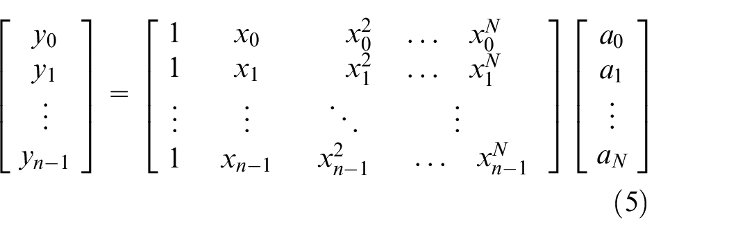
Hence, in matrix form, the equation for a polynomial fit can be expressed as

This is solvable by premultiplying by the matrix transpose such that

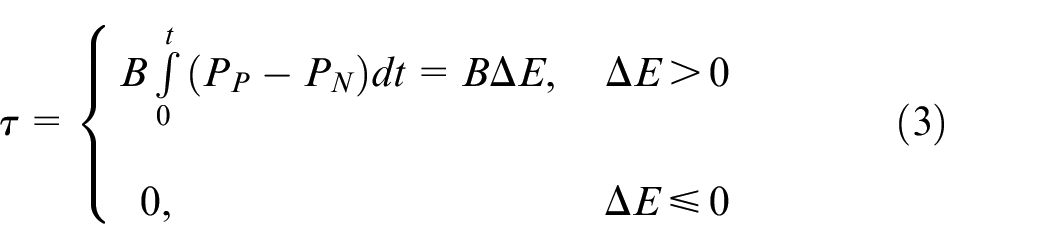
Thus, the theoretical expression of a second-order passivity-based adaptive delay compensator can be described as follows, where

The hybrid test with the delay compensator and passivity controller are shown in Figure 1 which illustrates a block diagram of the system where N(s), T(s), A(s), and P(s) denote the transfer functions of the numerical substructure, delay compensator, actuator, and physical substructure, respectively.
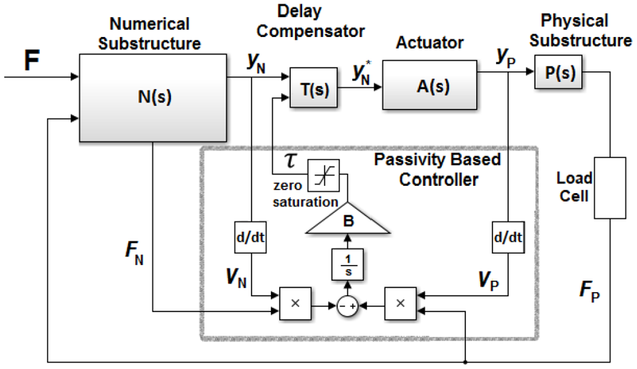
Structure of passivity-based delay compensator in hybrid test block diagram.
Experimental setup
In order to demonstrate the PBADC scheme, a single degree of freedom nonlinear real-time hybrid test system was set up. The numerical substructure consisted of a lumped parameter mechanical system of a mass suspended on a linear spring and viscous damper, while the physical substructure consisted of a stiffening spring. A diagrammatic view of the system is shown in Figure 2.
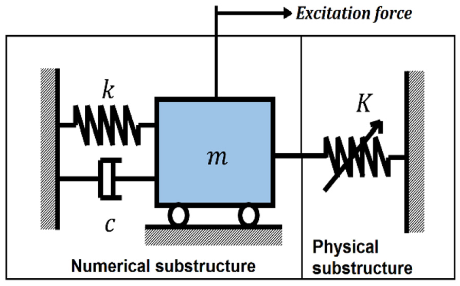
Mechanical system to be emulated by hybrid test.
The stiffening behaviour of the physical substructure was achieved by connecting two linear springs perpendicularly to the actuator such that displacement dependent stiffening is achieved much like a Duffing oscillator. Figure 3(a) shows the experimental system consisting of the actuator connected to the physical substructure. A zoomed in view of the physical substructure is given in Figure 3(b).
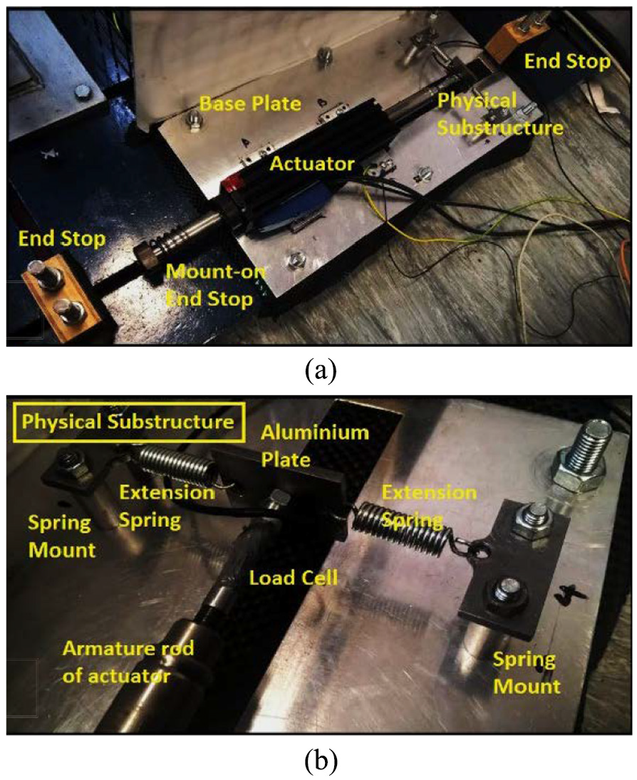
(a) Actuator connected to physical substructure through load cell; (b) view zoomed into physical substructure. 9
For actuation, a Copley STA2508S electromagnetic linear actuator is used which runs in position control mode, with cascaded current and velocity control loops as shown in Figure 4. For real-time control, a Simulink Real-time Target is used to execute the position and velocity loops while the current loop runs in the Xenus XTL motor driver. Due to nontrivial friction acting on the actuator shaft, a simple Coulomb friction compensator as proposed by Eamcharoenying et al. 10 is utilized, although due to the complex nature of the friction, complete elimination of friction is not achieved albeit it is reduced to a notable extent.
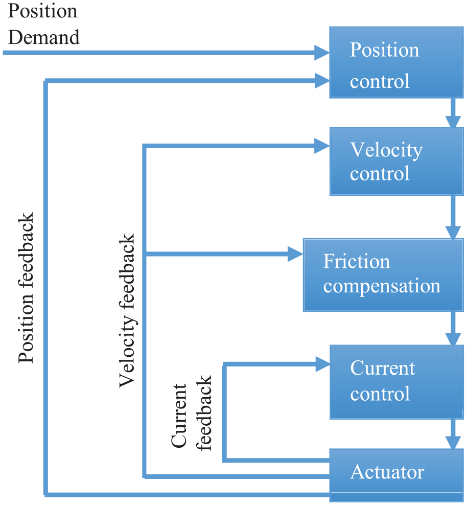
Actuator control system structure. 11
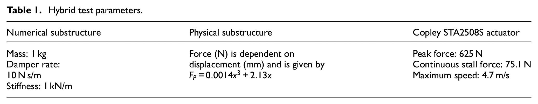
Table 1 presents the parameters of the hybrid test. The results presented in section ‘Experimental results’ compare the output of the hybrid tests with that of the emulated system, that is, the true system to be replicated. The emulated system was created in simulation after identification of the physical substructure force profile using the load cell.
Hybrid test parameters.
Experimental results
The aforementioned hybrid test and its emulated system simulation were excited at the numerical substructure using a stepped sine force input from 0 to 40 s. Frequencies of 0.1, 1, 5, 10, 20 Hz were applied at times 0, 20, 25, 30, 35 s. The amplitude of the force input for each step was chosen such that the physical substructure vibration amplitude would be 5 mm, to maintain consistency among tests given the displacement dependent stiffness of the physical substructure. The hybrid test position response of the physical substructure with and without passivity-based delay compensation is plotted against the response of the emulated system in Figure 5(a)–(f). The response of the hybrid test with the application of an adaptive delay compensation scheme by Wallace et al. 7 is also shown for comparison. The passivity-based compensator monitors the energy flow of the system throughout the hybrid test to identify the delay in the transfer system, while the scheme by Wallace et al. 7 identifies the delay in the system based on the substructure position gap measured at the zero crossings.
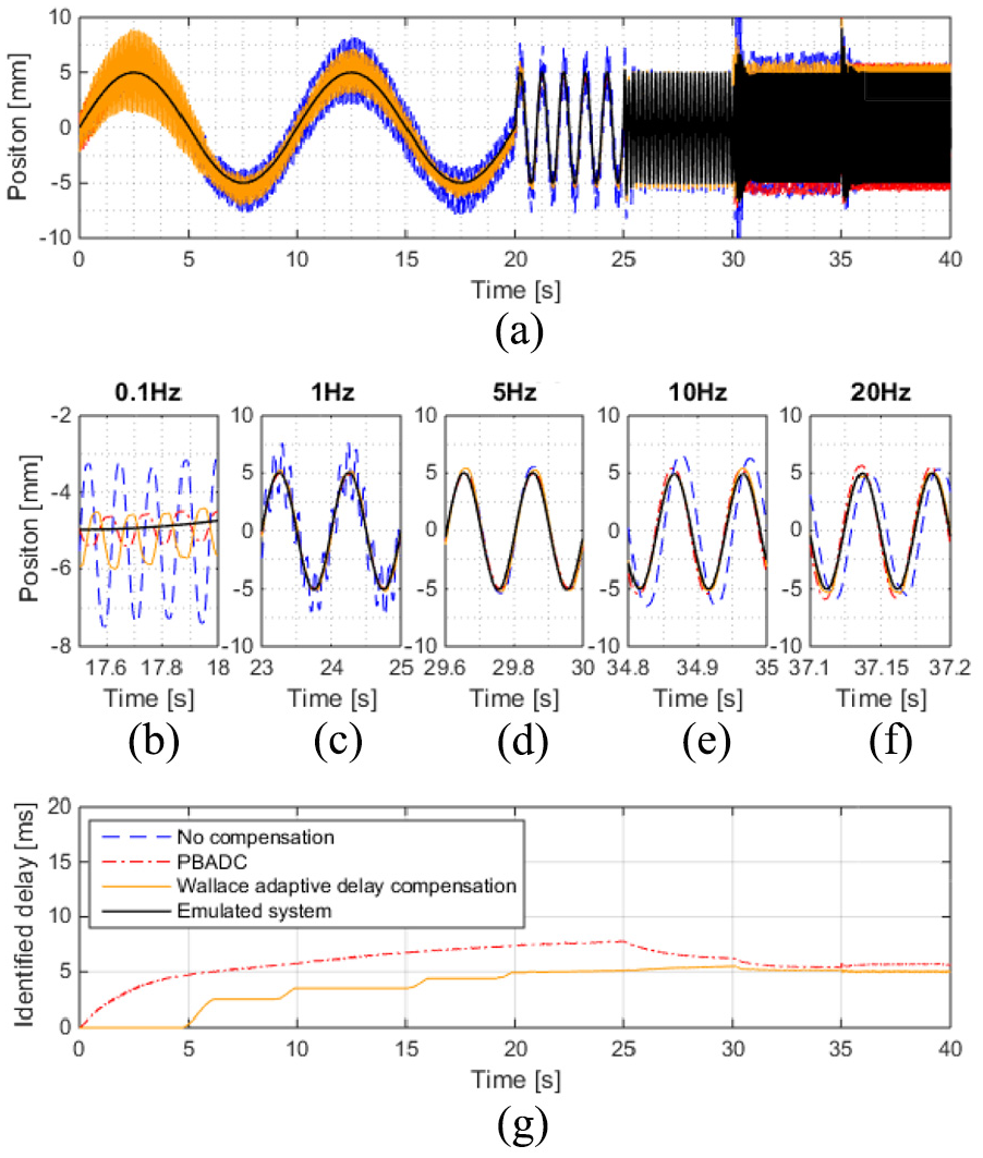
Compensated hybrid test responses: (a) physical substructure position envelope; (b–f) zoomed in views of physical substructure position at frequencies of 0.1, 1, 5, 10, 20 Hz; and (g) identified delay.
Figure 5(b) illustrates that the hybrid test response at 0.1 Hz is very oscillatory. While following the 0.1-Hz demand, the system also exhibits a limit cycle at 8.3 Hz. This is an artefact caused by the nonlinear friction of the actuator as described in Peiris et al. 9 At low velocities, the actuator phase lag due to friction is high resulting in an unstable system. As velocity grows due to the instability, the actuation forces dominate over the forces of friction and the system becomes stable once again, manifesting as a limit cycle at the natural frequency of the system. 9
It can be seen that the oscillatory nature of the response at 0.1 Hz is greatly reduced with the application of passivity-based delay compensation. The delay compensation alleviates some of the phase lag of the actuator which enables the stability of the system to be restored at lower velocities thereby leading to a smaller limit cycle. The delay compensation by Wallace’s adaptive scheme too exhibits a reduction in the amplitude of the limit cycle, however to a smaller extent. Particularly, as seen in Figure 5(a), Wallace’s compensation scheme does not show an improvement in the response until after 5 s. This is due to the nature of adaption as seen in Figure 5(g), which plots the delay identification of both compensators in the hybrid test.
The passivity-based delay compensator adapts to the current state of the system by updating the delay identification based on the passivity of the actuator in the hybrid test. A delay in the transfer system manifests as a surplus in the energy inflow from the actuator and physical substructure compared with the energy outflow from the numerical substructure. When such non-passive behaviour is seen, the passivity controller acts upon this energy surge to raise the delay identification. This delay which is input to the delay compensator will then result in stronger delay compensation which works to restore the passivity of the transfer system resulting in the energy surplus decreasing overtime and reaching an equilibrium when the net energy inflow matches the net energy outflow. Energy equilibrium is achieved when the phase lag between numerical and physical substructure displacements is removed. When operating conditions shift resulting in different actuator behaviour, further energy surges from the transfer system may be imminent, thereby allowing the delay identification to be tuned again till phase lag is eliminated and energy equilibrium is reached once more. This is a continuous process thus enabling passivity monitoring and delay compensation to be a process active throughout the hybrid test.
However, Wallace’s method which only updates the delay identification at the zero crossing is seen to respond much slower with the delay being updated only at 5, 10, and 15 s for the 0.1-Hz response. This means that a finite number of cycles will be required to allow Wallace’s adaptive delay compensator to converge and for low-frequency signals, this may lead to large settling times. Moreover, as the method only updates the delay when the measured position crosses zero, the scheme will not be directly applicable when the system response has no zero crossings (e.g. when excited by step or ramp inputs). In such cases, passivity-based delay compensation poses a unique advantage.
At 1 Hz as shown in Figure 5(c), both compensators successfully mitigate the limit cycle oscillation seen in the hybrid test response without compensation. At 1 Hz, the time at which the system is at low velocities is smaller resulting in a less significant limit cycle. At 5 Hz, the response without compensation is seen to be similar to that of the emulated system in Figure 5(d). In Figure 5(e), the amplitude of oscillation of the uncompensated hybrid test exceeds that of the emulated system. This phenomenon takes place because the excitation frequency of 10 Hz is near the resonant frequency of the system (8.3 Hz as seen from the limit cycle). Both compensation schemes are seen to mitigate this effect. There is notable phase lag in the uncompensated hybrid test responses at 10 and 20 Hz as seen in Figure 5(e) and (f). A phase lag of 35.6° is seen at 10 Hz and 35.3° at 20 Hz in Figure 5(e) and (f), respectively. As earlier, both compensation schemes are seen to effectively mitigate this phase lag although Wallace’s method achieves this with greater accuracy to that of the emulated system than the passivity-based method.
In Figure 5(g), it is evident that the delay estimates of both schemes are similar after 30 s (10- and 20-Hz tests). However, from 0 to 30 s, the Wallace delay compensation scheme takes longer to identify the transfer system delay due to its discrete operation at the zero crossings compared to the continuous operation of the passivity-based method.
Conclusion
The performance of a novel passivity-based adaptive delay compensator for real-time hybrid tests has been assessed. The scheme has been shown to improve stability and tracking in a single degree of freedom nonlinear real-time hybrid test. Performance of the scheme has been compared with that of a state-of-the-art adaptive delay compensation strategy, and performance was seen to be largely similar. However, the novel passivity-based approach enables the advantage of continuous monitoring of the actuator delay unlike the state-of-the-art method. This enables faster convergence while also being applicable to systems that do not cross zero. Therefore, PBADC is envisaged to be particularly useful with non-sinusoidal drive signals such as steps or unidirectional inputs where the system does not return to its original position. Future work will see further investigations in this regard while testing the scheme in multi-degree of freedom systems with nonlinearities in the numerical substructure as well.
Footnotes
Appendix 1
Declaration of conflicting interests
The author(s) declared no potential conflicts of interest with respect to the research, authorship, and/or publication of this article.
Funding
The author(s) disclosed receipt of the following financial support for the research, authorship, and/or publication of this article: This work has been supported through funding from the Engineering and Physical Sciences Research Council, grant reference EP/N032829/1.