
Abstract
The analysis and control of powertrain systems of electric vehicle, which is an important type of new energy vehicle, have been the focus of extensive research, but determining the motor modeling parameters remains a problem. A method of parameter determination for brushless DC motor modeling based on vehicle power performance was developed in this study. The power and torque of the driving motor of an electric vehicle were obtained by using the dynamic equation of the electric vehicle to satisfy the requirements of power performance. The ranges of the back electromotive force coefficient and the winding inductance were derived from the voltage and dynamic equations of brushless DC motor, which were deduced from the expected power and torque of the motor. The modeling parameters were then determined on the basis of the influence of power source voltage, back electromotive force coefficient, winding inductance, and winding resistance on vehicle power performance. A hardware-in-loop simulation of vehicle power performance was performed to verify the effectiveness of the proposed method. Results indicate that the maximum vehicle velocity is 172 km/h, and the acceleration time of 100 km/h is 13 s, which reveal that the motor modeling parameters obtained with the method satisfy relevant requirements.
Introduction
The development of new energy vehicles is an important endeavor in the automotive industry from the perspective of energy crisis mitigation and environmental protection.1,2 As an important type of new energy vehicle, electric vehicles have become a popular research topic, and their power systems have been extensively studied, particularly with regard to system parameter matching and optimization, motor control, and energy management. Brushless DC motors (BLDCMs) have been widely used in electric vehicle power systems given their advantages of high energy density, simple control, stable operation, and good speed control performance. 3 However, a driving motor model must be established to implement parameter matching and optimization for electric vehicle power systems, and analyze and control these systems.4,5 A key but challenging task before modeling is to determine the modeling parameters of a motor. On one hand, numerical simulation offers advantages of high efficiency, low cost, and reduced development time; the numerical simulation of motor control systems is a common method for verifying the effectiveness of control strategies.6–8 On the other hand, the modeling parameters of a motor must be determined before establishing a simulation model of the motor control system.
Power performance must satisfy the dynamic power demand of an accelerating and/or climbing vehicle. Therefore, knowledge on the performance parameters of vehicles is important. Power performance is typically evaluated with three indexes, namely, 100 km/h acceleration time, maximum velocity, and maximum climbing gradient, all of which are guaranteed by the vehicle powertrain. The power performance of a driving motor, which is the main power source of electric vehicles, directly determines the power performance of such vehicles. The parameters of power performance, including maximum and rated power, speed, and torque, must be calculated on the basis of design targets, such as acceleration time, maximum velocity, and maximum grade ability, in order for the model of the driving motor or designed motor to satisfy global power requirements9,10 or typical power requirements defined by a driving cycle, such as the New European Drive Cycle. 11 Only a well-matched powertrain can provide electric vehicles with good power performance to achieve maximum acceleration, maximum velocity, maximum gradient, and so on.
The most commonly used method for determining the power performance parameters of a driving motor is parameter optimization. In this method, the torque scaling factor, 12 rated/peak power, and rated/maximum speed of the driving motor 13 are treated as design variables, whereas demanded power, torque, and other limitations are treated as constraints. With the aid of an optimization algorithm, the optimal values of the design variables can be searched under the guidance of a certain optimization object. Power performance parameters can also be determined by using a vehicle dynamics model14,15 when only certain requirements, instead of specific optimal values, need to be satisfied. However, power performance parameters alone cannot adequately model a motor when verifying if an electric vehicle can satisfy power performance requirements or when providing direct guidance to motor design.
The power performance parameters of a motor are influenced by electric parameters, such as battery voltage, back electromotive force (EMF) coefficient, and winding resistance and inductance. These parameters are crucial in establishing a driving motor model and designing the motor. One of the common methods for determining motor modeling parameters is parameter identification, which is aimed at accurately estimating motor parameters, including stator inductance, stator resistance, rotor flux linkage, and load torque.16,17 Another method is the cluster technique, which uses information on stator currents, stator voltages, and rotor angular speed, to identify electrical parameters, 18 while other methods consider perturbation and temperature. 19 Although these methods can accurately identify motor electrical parameters, no ready-made motor can be used to perform experiments for parameter identification during the initial development of an electric vehicle. At this stage, engineers may need to match powertrain with electric vehicle power requirements. Then, the powertrain with the driving motor in the vehicle dynamics model is used to perform simulation for power performance verification. Thus, a technology for determining motor modeling parameters must be developed to meet power performance requirements.
In this study, a method for determining the motor modeling parameters of electric vehicles is developed on the basis of power performance requirements, from which motor power and torque requirements are determined. The effective range of the modeling parameters under motor mechanical constraints is established, and the motor modeling parameters are selected from the range based on the influence of these parameters on power performance. The proposed method is verified by conducting a hardware-in-loop (HIL) simulation.
Vehicle power performance requirements
When a vehicle is climbing slope α at initial velocity v and acceleration a, the running resistance mainly includes rolling resistance, air resistance, acceleration resistance, and ramp resistance, as shown in Figure 1.
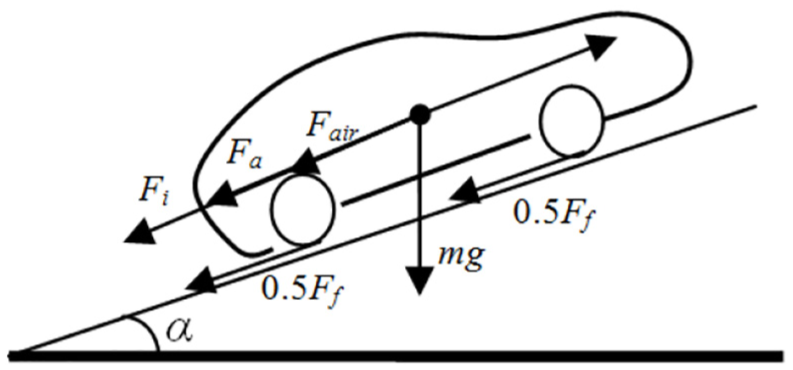
Analysis of force in the vehicle driving process.
Running resistance can be expressed as follows


where Ff is the rolling resistance provided by the ground, m is the overall mass of the vehicle, g is the gravitational acceleration constant, µ is the rolling resistance coefficient between tire and road, α is slope angle, Fair is air resistance, ρ is air density, A is vehicle frontal area, Cd is the air resistance coefficient, v is instantaneous velocity, Fa is acceleration resistance, δ is the transfer coefficient of rotating mass, and Fi is ramp resistance.
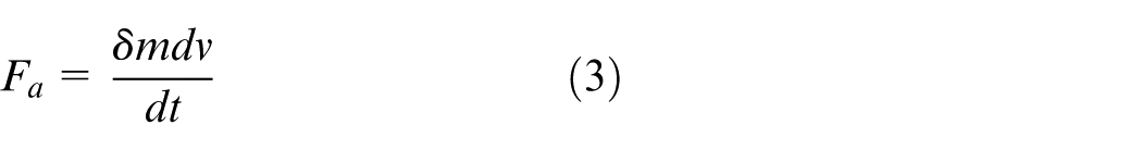
The driving force of the drive motor output is used to overcome running resistance, and the relationship between driving torque Te and driving force Ft is
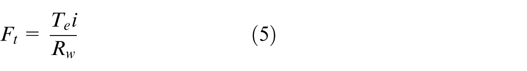
where i is the transmission ratio and Rw is the rolling radius.
When an electric vehicle is driven at velocity v on an uphill road with slope α, the required power is
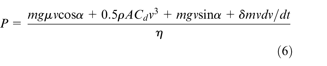
where
Similar to traditional internal combustion engine-driven vehicles, the indexes of power performance of electric vehicles include maximum velocity, maximum climbing degree, and acceleration capability. The motor power requirements of these indexes are as follows.
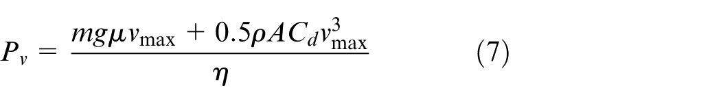
When an electric vehicle is running at the maximum velocity of Vmax, the required power is
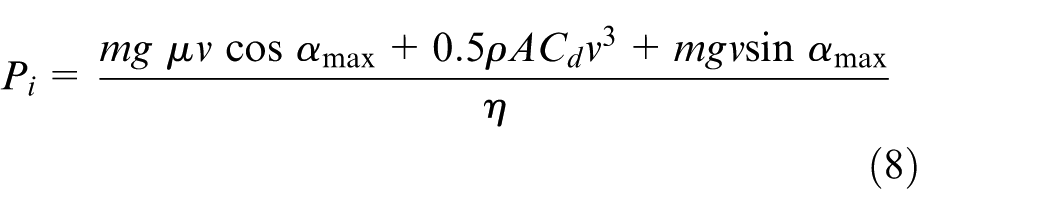
When an electric vehicle running along an uphill road with a maximum slope of αmax has a velocity of v, the required power is
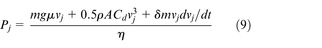
When an electric vehicle is running along a horizontal road and accelerates from static to velocity Vj within time t, the required power is
The peak power of the motor meets the requirement of vehicle power performance when

BLDCM mathematical model
For a six-state three-phase star-shaped BLDCM with two-phase conduction, certain assumptions are considered when modeling the motor and analyzing and controlling the electromagnetic torque.
The three-phase winding is symmetrical, the air gap of the magnetic field is a square wave, and the stator current and the magnetic field distribution of the rotor are symmetrical.
The effects of the slot, commutation process, and armature reaction are ignored.
The armature windings are evenly and continuously distributed on the inner surface of the stator.
The magnetic circuit is not saturated regardless of eddy current and hysteresis loss.
An equivalent circuit of BLDCM is shown in Figure 2. In the figure, Ua, Ub, and Uc are three-phase voltages; Ia, Ib, and Ic are three-phase stator currents; Eb, Ea, and Ec are the back EMFs of the three phases; Ra = Rb = Rc = R denotes the stator resistance of the three phases; L is the identical self-inductance of the phase stator winding; and M is the identical mutual inductance between any two phase windings. The inductance of each phase winding is defined as L – M.
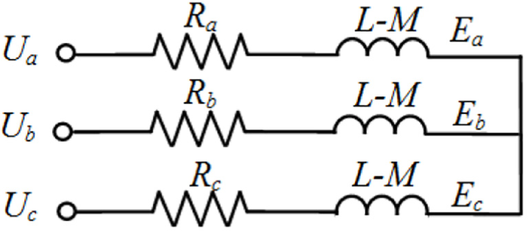
Equivalent circuit of BLDCM.
The voltage equation of the three-phase winding of BLDCM is
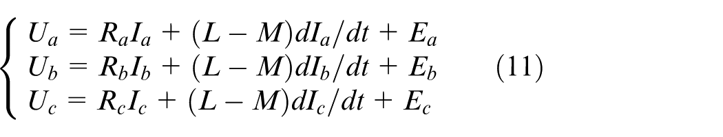
At any moment, the BLDCM stator has only two-phase conduction. When phases A and B are conducted, Ia = –Ib = Is and Ea = –Eb = Es. Thus, equation (11) can be rewritten as

The electromagnetic torque of BLDCM is generated by the interaction between the current in the stator winding and the magnetic field produced by the permanent magnet of the rotor
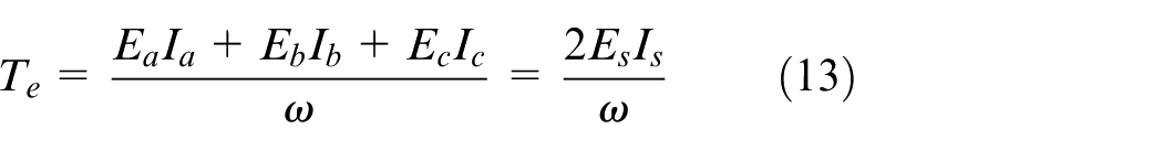
where ω is the mechanical angular speed of the motor.
According to the relationship between the single-phase back EMF of BLDCM and the rotational speed

where Ke is the back EMF coefficient.
By using equations (13) and (14), the following expression can be obtained

According to equation (15), the electromagnetic torque of BLDCM is proportional to the current under a given back EMF coefficient.
Ud = Ua – Ub is defined as the line voltage, which is the power supply voltage, and it can be obtained from equation (12) as follows

The rotor dynamic equation of a motor is expressed as
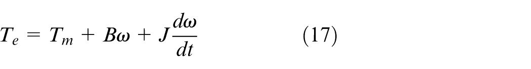
where Tm is the load torque, J is the motor inertia, and B is the motor damping coefficient.
According to the mathematical model of BLDCM, the main electrical parameters of motor modeling are power supply voltage, back EMF coefficient, winding inductance, and winding resistance. The parameter determination method proposed in this work was applied to the derivation of these four electrical parameters.
Determination of modeling parameters
Power and torque matching
According to the power performance requirements of vehicles, the external characteristic parameters of BLDCM must satisfy the maximum power requirement, that is, motor maximum power Pmax must satisfy the condition expressed by equation (10). Similarly, the maximum torque of BLDCM should ensure that the electric vehicle can provide sufficient torque during acceleration and that the torque satisfies the required maximum gradient of the electric vehicle. Therefore, the maximum torque of the motor is likely related to the maximum transmission ratio imax of the transmission system and the maximum slope αmax. The formula of Tmax is
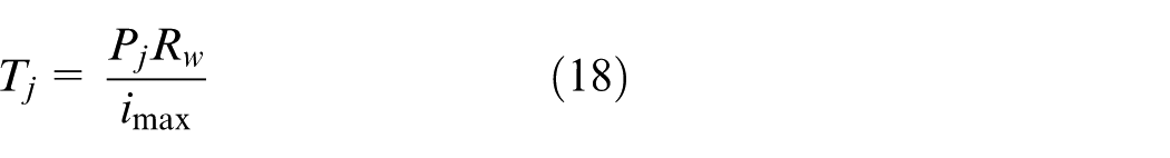

where Rw is the wheel radius.
The rated power of BLDCM is the power at which the motor can operate for a long time with stable output torque and relatively high efficiency. To ensure the energy economy of the vehicle at high velocity, and to meet the power requirements of near-constant velocity driving conditions and small-slope driving conditions, the power of a vehicle running at 90% of the maximum velocity (i.e. 120 km/h in China, the maximum velocity limit) is defined as the rated power.14,20 When calculating the rated power of BLDCM, only the rolling resistance and air resistance of the vehicle should be considered. Referring to equation (7), the rated power of a motor is calculated as
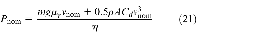
where vnom is the rated velocity of electric vehicles.
The rated torque Tnom of a motor is calculated on the basis of rated power Pnom as follows
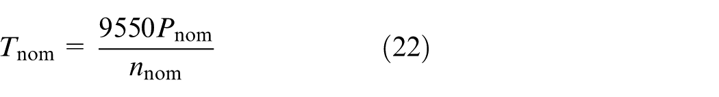
where nnom is the rated speed of the motor.
Determination of characteristic speed
BLDCMs have three characteristic speeds: rated, maximum, and base speed. The characteristic speeds of motors should be determined on the basis of the transmission ratio, motor efficiency, and continuous running characteristics of electric vehicles. Motor rated speed nnom is the rotational speed of the motor when a vehicle is running at rated velocity vnom. The unit of measure for nnom is r/min, and it is calculated as
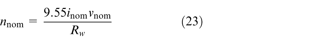
where inom is the transmission ratio of the driveline at the rated speed and is generally the highest gear ratio.
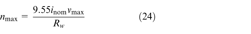
The maximum speed nmax of a motor is the rotational speed of the motor when a vehicle is running at maximum velocity vmax. If the transmission ratio is inom at this time, then the maximum speed is
The basic speed of the motor is a key parameter of BLDCM, and it is also the turning point of constant torque and constant power in the torque speed characteristic curve. In other words, the constant maximum torque can be obtained when the motor is starting or running below the base speed, which satisfies the requirements of low speed with large torque when the electric vehicle starts running. When the motor speed is higher than the base speed, the motor outputs constant power and satisfies the requirements of a vehicle running at high speed. The basic speed of a motor is expressed as
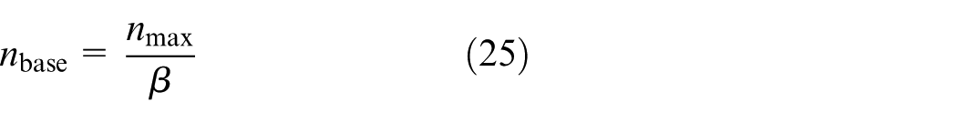
where β is the base speed ratio, which is set to 4–5 for passenger cars. 21
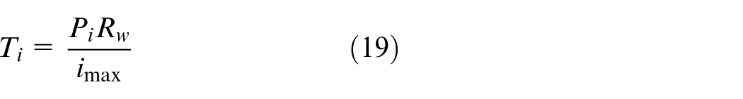
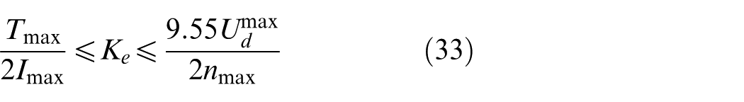
Determination of back EMF coefficient
In consideration of electrical safety, the maximum allowable current of the stator is defined as Imax. According to equation (15), when the motor outputs the maximum torque, the stator current cannot exceed the maximum current Imax, that is
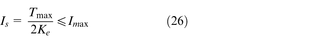
Hence

The BLDCM stator only has two-phase conduction at any time. When A and B are conducted, the derivative of the current is zero, and only the flat part of the trapezoidal phase current (i.e. constant current) is considered. Thus, equation (16) can be rewritten as

The voltage drop of the stator winding is small and can be ignored. Equation (28) can be approximated as

Substituting equation (14) with equation (29) yields

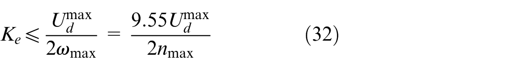
According to equation (29), line voltage is proportional to motor speed for a given back EMF coefficient. To ensure that the maximum line voltage of the motor does not exceed the maximum voltage of the battery when the electric vehicle is running at the maximum velocity, we set

where
Thus
With equations (27) and (32), the range of the back EMF coefficient can be obtained as
Inductance determination
The winding inductance of a motor is a key influencing parameter of the mechanical characteristics of the motor, and it is a factor that determines the power of electric vehicles. The mechanical characteristic of a six-state three-phase star-shaped BLDCM with two-phase conduction is defined as follows 22
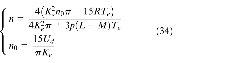
where n is the motor speed, and n0 is the motor no-load speed.
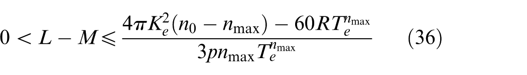
When an electric vehicle runs at the maximum velocity, the output torque of the motor must satisfy the running resistance at this moment
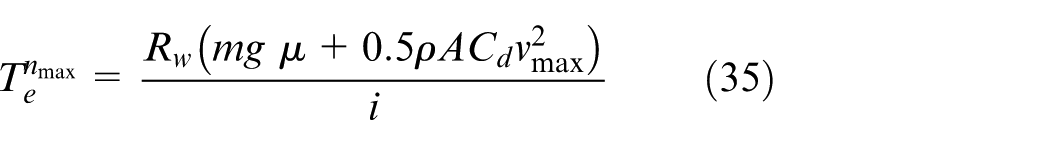
Therefore, the winding inductance must satisfy the following condition
Determination and verification of the motor modeling parameters
Determination of the motor modeling parameters
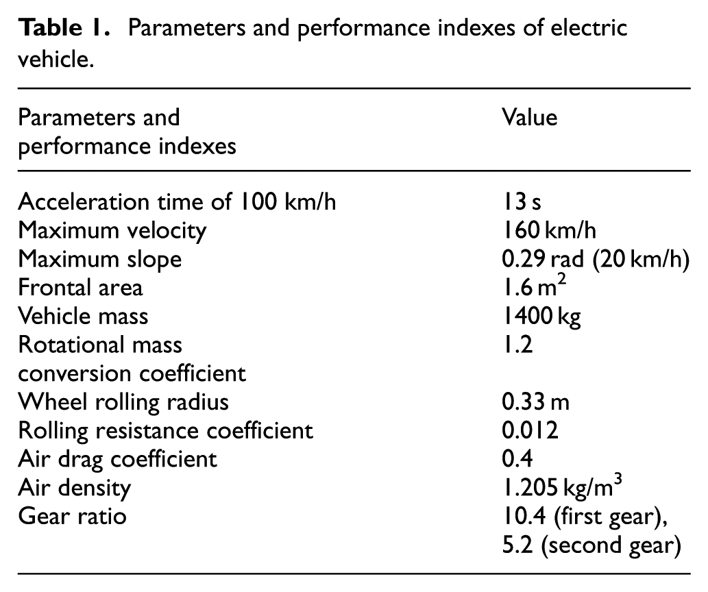
For BLDCM to satisfy the power demands of electric vehicle, the maximum power and the maximum torque of the motor must be determined on the basis of the power performance of the vehicle. Then, the rated speed, maximum speed, and characteristic speed of the motor are determined. By referring to the power supply voltage and winding resistance of electric vehicles of the same type, the motor back EMF coefficient can be calculated by using the motor voltage equation. The range of winding inductance is subsequently obtained from the mechanical characteristics. Then, the modeling parameters of the motor are determined and adjusted according to the influence law of the modeling parameters on power performance. In this work, an electric vehicle was selected as the research object to determine the modeling parameters of BLDCM. The parameters and power indexes of the electric vehicle are listed in Table 1.
Parameters and performance indexes of electric vehicle
We applied a predetermined power supply voltage of 400 V by referring to electric vehicles of the same type. The winding resistance was set to 0.025 Ω, and the pole number was 2. Referring to equation (33), the range of the back EMF coefficient was determined to be 0.17 V/(rad/s) ⩽ Ke ⩽ 0.31 V/(rad/s). The winding inductance was L – M ⩽ 0.5 e–3H when equation (36) is used. The preliminary modeling parameters of BLDCM are presented in Table 2, and this parameter set is designated as parameter set 1.
Modeling parameters of BLDCM.
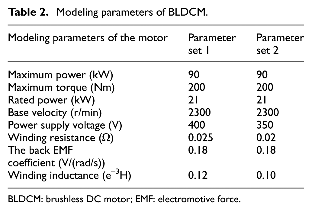
BLDCM: brushless DC motor; EMF: electromotive force.
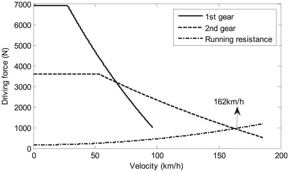
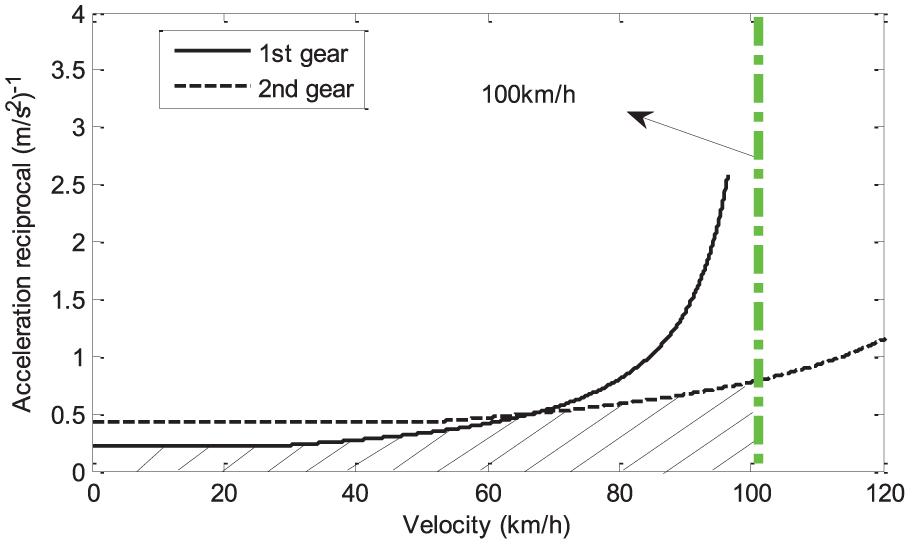
Motor model and running resistance are established on the basis of power supply voltage, back EMF coefficient, winding inductance, and winding resistance, as listed in Table 2. The balance between driving force and running resistance of the electric vehicle is shown in Figure 3. The solid line in the figure denotes the driving force in the first gear; the dashed line represents the driving force while the transmission in the second gear; and the dotted line is the running resistance. The solid line shows that the maximum velocity of the electric vehicle is 96 km/h in the first gear, which does not satisfy the power performance requirement of the maximum velocity of 160 km/h. The intersection point of driving force in the second gear and running resistance shows that the maximum velocity of the vehicle is 173 km/h, which satisfies the requirement of the maximum velocity of 160 km/h. The acceleration reciprocal curve of the electric vehicle is shown in Figure 4, in which the solid and dashed lines represent the reciprocal of the acceleration of the electric vehicle running in the first and second gears, respectively. Findings show that the electric vehicle cannot accelerate to 100 km/h in the first gear, which is consistent with the data in Figure 3. In the second gear, the vehicle can accelerate beyond 100 km/h. The enclosing region between the acceleration reciprocal curve and the 100 km/h straight line (i.e. shadowed area in Figure 4) is the acceleration time required by the electric vehicle to accelerate to 100 km/h. By using the trapezoidal area superposition method to calculate the area of the shadowed region, we have determined that 12.6 s was the time needed by the electric vehicle to accelerate to 100 km/h. As shown in Figures 3 and 4, the maximum velocity and the acceleration time both satisfy the power performance requirements of the electric vehicle, thereby the power supply voltage, back EMF coefficient, winding inductance, and winding resistance are validated.
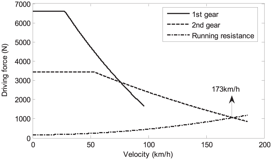
Equilibrium diagram of driving force and running resistance (parameter set 1).
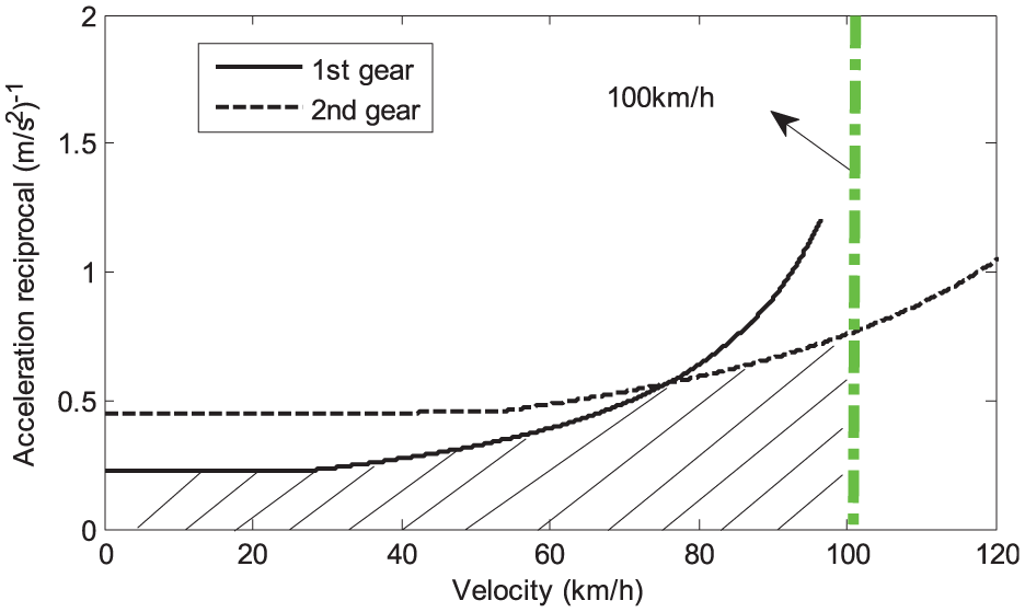
Reciprocal acceleration curves (parameter set 1).
According to equation (30), line voltage Ud is proportional to back EMF coefficient Ke at a given motor speed. If the selected Ke is excessively large, then the battery voltage must be increased. Additional battery cells must be connected in series, which will increase vehicle weight and manufacturing cost. Furthermore, high voltage may present new challenges to vehicle safety. Although battery voltage can be reduced by decreasing Ke, doing so will lower the no-load speed of the motor, as depicted by equation (34). Consequently, the power performance requirements of the maximum velocity will not be satisfied by the electric vehicle. The effects of the four parameters (i.e. power supply voltage, back EMF coefficient, winding inductance, and winding resistance) on the maximum velocity and the acceleration time are shown in Table 3.
Effects of motor parameters on power performance.
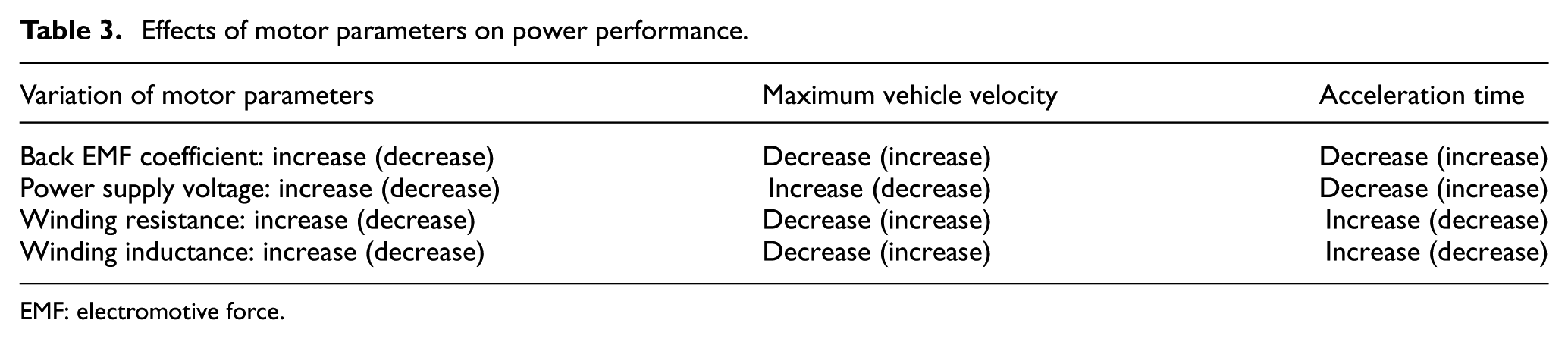
EMF: electromotive force.
Table 3 shows that increasing the back EMF coefficient of the vehicle improves acceleration performance but decreases maximum velocity. Meanwhile, increasing power supply voltage not only increases maximum velocity but can also improve acceleration performance, and this is why current electric vehicles generally use high-voltage platforms. When winding inductance and winding resistance are both decreased, power performance is improved. However, decreasing winding inductance may cause the phase current to become non-continuous, resulting in eddy current loss and increased motor power consumption. This scenario is also unfavorable for torque ripple suppression. Winding resistance can be reduced by increasing the wire winding diameter or by using new low-resistivity materials, but they will increase motor size or cost. Thus, the final selection of the four parameters entails a compromise on overall vehicle power performance. For example, decreasing power supply voltage may result in the decrease of maximum velocity and acceleration time, but these defects can be compensated by reducing the winding inductance and winding resistance at the same time. Other parameters are defined as parameter set 2 and presented in Table 2, in which Ud = 350 V, Ke = 0.18 V/(rad/s), L – M = 0.10 e–3H, and Ra = 0.02 Ω. Compared with parameter set 1, the power supply voltage, winding inductance, and winding resistance in parameter set 2 are reduced simultaneously.
The balance between driving force and running resistance and the acceleration reciprocal curve are illustrated in Figures 5 and 6, respectively. The time required by the electric vehicle to accelerate to 100 km/s is 12.1 s. The maximum velocity is greater than 160 km/h, indicating that parameter set 2 also satisfies the power performance requirements of electric vehicles. A comparison of the modeling values of parameter set 1 and parameter set 2 suggests that the maximum velocity of the latter is lower although its acceleration performance is stronger. This result suggests that a decrease in power supply voltage affects the maximum velocity of the vehicle. If the back EMF coefficient Ke is reduced from 0.18 to 0.16 V/(rad/s), then the maximum velocity can be increased to 170 km/h, and the acceleration time of 100 km/h can also be increased to 12.8 s. In using this method, a power performance similar to that of parameter set 1 can be achieved.
Equilibrium diagram of driving force and running resistance (parameter set 2).
Reciprocal acceleration curves (parameter set 2).
Vehicle power performance verification based on the HIL
To verify if the BLDCM modeling parameters satisfy the power performance requirements of electric vehicles, we established an accurate vehicle dynamics model by using the vehicle dynamics simulation software CarSim with the parameters listed in Table 1. The predefined vehicle dynamics model template, which included vehicle mass, tire, and aerodynamic parameters, was modified. The driving system was disconnected, and the power source was set to the external import. In the reference vehicle, the two-gear transmission mode was selected for the analysis of the gear ratio. The inertia, transmission efficiency, and shift schedule of the vehicle were also modified for the gear ratio of the main gear reducer and the differential. The product of the transmission gear ratio and the main reducer gear ratio should be consistent with the gear ratios of the first and second gears, respectively. An existing motor whose parameters approximate the modeling parameters listed in Table 2 was considered. The dynamic analysis of the electric vehicle was implemented through HIL simulation (Figure 7). The test bench of the motor driving system is shown in Figure 8.
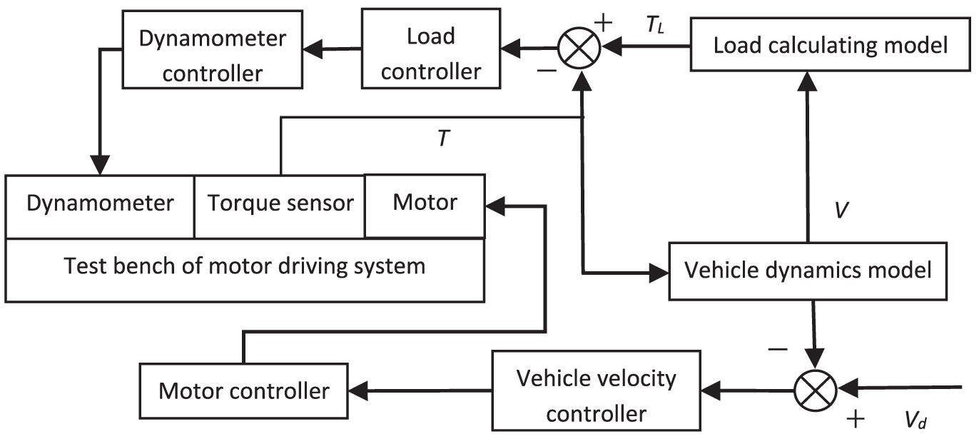
HIL simulation arrangement.
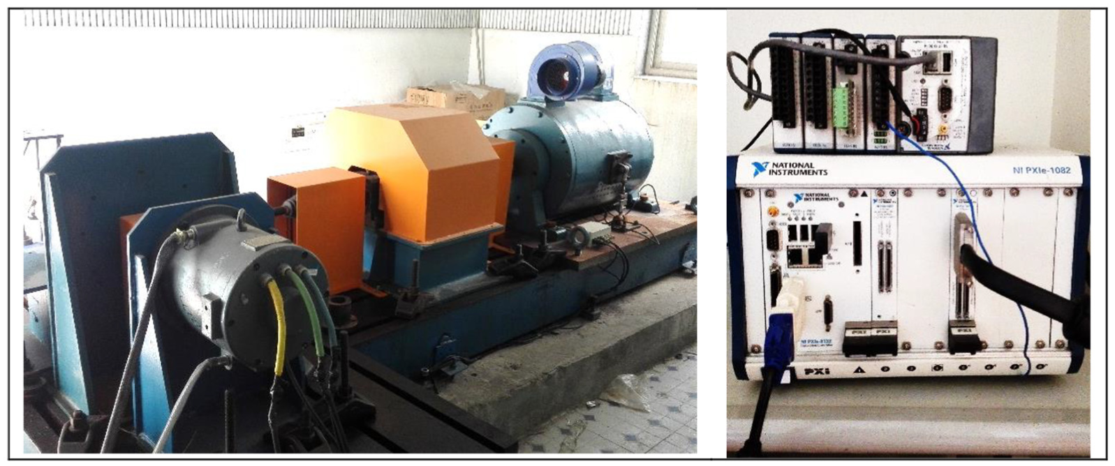
Test bench of the motor driving system.
In the HIL simulation process, a dynamometer was used to apply load to the driving motor. The output torque of the motor was transformed by torque sensor, and the signal was used as the input of the vehicle dynamics model. The load calculation model was used to calculate running resistance in current working conditions (i.e. equations (1)–(4)). A load controller was used to either increase or decrease the load depending on the deviation between load torque and measured torque. The load controller also outputted control signals to the dynamometer controller to ensure load control on the dynamometer. A vehicle velocity controller was used to send either acceleration or deceleration command to the motor controller depending on the deviation of the desired vehicle velocity and the actual vehicle velocity that were outputted by the vehicle dynamics model. A motor controller then completed the velocity control of the driving motor. The vehicle dynamics model, the load calculation model, and the vehicle velocity controller and the load controller are processed in real time and then deployed to the real-time controller PXIe 8133RT by using VeriStand. Signal inputs and outputs were implemented by using the multi-function data acquisition card NI-PXIe 6363.
The desired velocity inputted by the driver was used as BLDCM target speed after transmission ratio and unit conversion. The electromagnetic torque of BLDCM was inputted to the driving system of the vehicle dynamics model as the IMP_M_OUT_TC variable, and the motor load torque was converted from the four-wheel longitudinal force. In the model, the desired velocity has been defined as the ramp function by which the vehicle can accelerate from standstill to 100 km/s in 13 s. The acceleration was 2.14 m/s2. Figure 9 illustrates the velocity curve of the electric vehicle. As shown by the diagram, the maximum velocity is 172 km/h, which satisfies the maximum velocity requirement of 160 km/h. During the acceleration process, the actual velocity can accurately track the desired velocity until the desired velocity exceeds 130 km/h. This result verifies that acceleration time satisfies the requirement of 13 s. Thus, the modeling parameter set 1 of the motor can satisfy the maximum velocity and acceleration performance requirements of the vehicle. When the road slope is set to 0.29 rad, the electric vehicle can climb it at the velocity of 20 km/h, indicating that the modeling parameters can also satisfy the performance requirements of the maximum climbing slope.
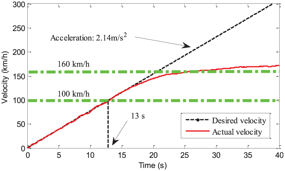
Verification of power performance of the electric vehicle.
Conclusion
On the basis of the vehicle dynamics, voltage balance, and rotor dynamic equations of BLDCM, a method for determining the modeling parameters of a motor was proposed to satisfy the power performance requirements of electric vehicles. Parameter determination and power performance evaluation were established and analyzed, and some conclusions were obtained. The maximum current and the maximum voltage are two parameters that determine the range of the back EMF coefficient of a motor. The mechanical characteristics of the motor, which should satisfy the driving characteristics of the electric vehicle, determine the range of motor inductance. Meanwhile, the battery voltage is positively related to vehicle power, whereas winding inductance and winding resistance are negatively related to vehicle power. The back EMF coefficient is negatively correlated with maximum velocity but positively correlated with acceleration performance. The equilibrium diagrams of driving force and running resistance and the co-simulation results of CarSim and MATLAB/Simulink indicate that the determination method proposed in this work can guarantee the power performance of electric vehicles. Since the temperature has an important influence on the motor characteristics, the influence of temperature on motor parameters should be considered, and then a new determining method of motor modeling parameters considering the temperature influence could be proposed in the future works.
Footnotes
Declaration of conflicting interests
The author(s) declared no potential conflicts of interest with respect to the research, authorship, and/or publication of this article.
Funding
This project is supported by National Natural Science Foundation of China (grant no. 51675057) and the Scientific Research Fund of Hunan Provincial Education Department (grant nos 15B008 and 16C0906).