
Abstract
In the feedback control robotic systems, the repetitive control method has a high control performance for the track or elimination of the periodic signals. The promotion of the plug-in type configuration of the controller broadens the application range and applicability of the control method. In this article, a novel design algorithm based on the steady-state residual convergence ratio of the repetitive control system is proposed to improve the performance of the stabilized platform to resist the periodic perturbation. The basic structure and stable condition of the plug-in type repetitive control method are first introduced by applying the small gain theorem and the stability theorem for time-lag systems. Then the analysis of the convergence rate is utilized in constructing the basic index of the design algorithm of a plug-in type repetitive control system based on a steady-state residual convergence ratio. The parameters of the designed controller are checked by the validity condition of the plug-in type repetitive control system, and a simulation example is given to verify the effectiveness of the design algorithm. The article provides basic design guidelines and schemes for the design of the periodic disturbance suppression performance of the feedback control system. In the final physical prototype experiment, the prospective steady-state residual convergence ratio is basically achieved within the allowable range of error.
Keywords
Introduction
Repetitive control is a useful servo design tool for systems that are surrounded by periodic disturbances. Its application ranges from active vibration suppression in manufacturing processes (e.g. an imbalanced rotational machinery), hard disk drives, and even chemical processes (particular chemical reactors). As for space technology, an increasing number of high-precision aeronautic electronic equipment is applied to various airborne carriers to complete a variety of tasks. To achieve the precise pointing accuracy and inertial stability of the devices, a platform with perpendicular axis that can achieve inertial stability is the most extensively applied one used in moving carriers and aircrafts. Therefore, the stabilization precision is the core technical indicators for those platforms, but they are impeded by inevitable perturbation generated in the operation condition of the moving carriers. As for the aircraft carriers, the research reveals that the perturbation motion has a certain periodicity. In general, the vibration spectrum of the propeller-driven aircraft ranges from 15 Hz to 2000 Hz, which involves broadband random vibration and narrowband sharp periodic vibration. The combination of these frequencies forms the perturbation environment of the propeller-driven aircraft. The broadband random vibration is generated mainly by the stimulation from the airplane when it is sliding, taking off, and landing. The motivation of atmospheric turbulence and the vibration of the motors may also belong to the influential factors. While narrowband sharp random vibration is generated mainly due to the rotating pressure field excited by the rotation of the propeller blade. The center frequencies of those periodic vibrations load in the blade passing frequency, so the device installed on the propeller-driven aircraft is inevitably subjected to broadband random vibration effects of superimposing the narrowband one. 1 –5
For unmanned aerial vehicles, the majority of which are outfitted with propeller engines, the vibration source generated in flight is similar to that in a propeller-driven aircraft. The vibration environment is composed of broadband random spectrum superimposed narrow-band spikes. For helicopters whose rotor and the tail rotor system are the most important sources of vibration, the vibration environment is rather worse. When the helicopter is on-flight, the rotor and the blade in the tail rotor start to shimmy and generate torsion deformation due to the influence of the strong airflow. Periodic alternating force and torque come to be in the hub by then and transfer to the fuselage where the precise devices are installed. The value of the vibration frequencies generated in the helicopter generally equates to the products of the blade number and the working frequency of the rotor or the tail rotor. The vibration frequency also extends to the frequency multiplier, which constructs the periodic vibration–based vibration circumstance with broadband random vibration of low amplitude. Thus, the periodic disturbances exist in the aircraft are an important part of its perturbation circumstance. How to suppress the influence of periodic disturbance on the airborne-stabilized platform becomes a common problem faced in this area. What’s more, the periodic or approximately periodic signals appear frequently in both the external disturbances and the interior of control systems. Therefore, it is very important to realize error-free tracking and suppression of periodic signals.
In general, the external periodic disturbance can be suppressed by the improvement of mechanical construction, mainly by vibration isolation and damping technique. Vibration isolation technology is to set isolation mounting between the vibration source and the stabilized platform to eliminate or isolate the transmission of vibration. While the vibration damping technology is to add dampers to the vector system to deplete or shift the vibration power that tends to be transferred to the stabilized platform. This kind of passive vibration suppression method has advantages of high reliability, no energy consumption, simple structure, and economic practicality. However, it lacks flexibility to eliminate periodic signals for improving the mechanical structures that have obvious inhibition effect only on high-frequency disturbances and its application range is very limited.
The shortage of mechanical methods can be remedied efficiently by controlling means to suppress the repetitive disturbance. In traditional control methods, the major influencing factors are specifically compensated by building their observers on the basis of the servo loop. In practice, the use of various filters such as Kalman filter and notch filter are benefit to the efficiency of compensation. 6 –12 Besides, an increasing number of advanced control algorithms has been applied to eliminate the repetitive disturbance in a stabilized platform. The optimal control, variable structure control, neural networks, sliding mode control, active disturbance rejection control, and fuzzy control are most frequently used among them. 13 –16 However, the above-mentioned methods owe the character of universality and don’t aim for the disturbance of a particular frequency, which leads to undesirable behavior on the elimination of periodic signals.
The notch filter is a control method aiming at an exact frequency, but it has been greatly restricted in the engineering application because of its influence on the control stability. The algorithms based on the internal model help to create a linear regulator that can track harmonic disturbances. Savkin and Petersen give a necessary condition for the existence of a suitable robust controller that minimizes a quadratic cost. 17 Byrnes et al. illustrate a solution for continuous-time linear systems and extended to multiple-input multiple-output (MIMO) systems. 18 Lindquist and Yakubovich develop universal regulators in discrete-time systems. 19 Marino and Tomei 20 focus on the disturbance with unknown frequency and Bodson et al. 21 tie the separate harmonics together within the algorithm. Repetitive control theory that is also based on the internal model theory can be a new way to cope with the periodic perturbation. 22 The essence of the internal model principle is to embed the dynamic model of the external signal into the controller to form a high-precision feedback control system. Figure 1 shows the built-in pure delay link, which is the internal model of the repetitive controller and L is the cycle of the target signal. This kind of internal model whose output is the cycle-by-cycle accumulation of the input signal, in principle, can track or suppress periodic signals with no steady-state error.

The internal model of the repetitive controller.
The shortcoming of the harsh condition for the stabilization in the standard repetitive controller appears in the actual system, but the frequency of periodic signals that the control system needs to track or suppress does not need to reach infinity. To solve this problem, some scholars try to set a low-pass filter before the delay module so that the undesired high-frequency components are cut off to improve the repetitive controller. 23 The improved method is analyzed in detail and its exponential stabilization condition is given to extend this method to a multivariable control system. 1 The improved repetitive controller is called a plug-in type repetitive controller (abbreviated as PITRC) for it can be inserted into the control loop without affecting the performance of the original controller. The concept of regeneration spectrum for time-delay systems is introduced to evaluate the dynamic performance of the repetitive control system, combine with which the best trade-off between the control stabilization and accuracy is achieved by constructing the sensitivity and insensitivity function. 24 The design of the controller based on the parameter space is investigated and the relationship between the controller frequency domain and the controller structure parameters is established. 25 However, most of the earlier researches are limited in the stage of simulation and lack the support of physical prototype experiments. A second-order filter and a linear phase-lead link are used as a dynamic compensator of the repetitive controller and several standards for the selection of their parameters are proposed, but the results of the physical prototype experiment focus more on the optimizing function of the dynamic compensator and lack the ability to derive control parameters for specific system indicators. 26 This article mainly focuses on a quantitative design of the proper control parameters to achieve the expected accuracy of the system.
This article is organized as follows. First, in the second section, the basic structure of the plug-in type repetitive control system (PITR) is introduced. The stabilization condition, the validity condition, and the convergence rate are also deducted. The third section describes the selection criteria of the parameters in the low-pass filter and puts forward the design algorithm for PITR which is verified by a simulation. Experimental setup and results are given in the fourth section. The final section concludes this article.
Plug-in type repetitive control system analysis
Basic structure and stabilization condition of the PITR
The basic structure of the PITR is illustrated in Figure 2.

The block diagram of the PITR. PITR: plug-in type repetitive control system.
Form Figure 2, we can obtain 1

Assuming that there is no unstable zero-pole cancellation between

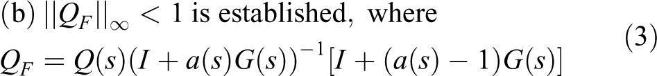
Then, the PITRC shown in Figure 2 is exponentially asymptotically stable. In addition, for variable reference signals of different periods, the residue signal of the system is bounded. Especially when
For simple input simple output (SISO) systems, condition (b) equates to

Then we have

Stability region of the PITR. PITR: plug-in type repetitive control system.
The basic stable condition of the plug-in type repetitive system is that

As for the single-input-single output situation discussed in this article, formula (5) can be transformed to be

When designing the low-pass filter, it is necessary to depict map

The frequency responses of
Then

Under the condition that the transfer function of the control object is already determined, both
The effectiveness conditions of PITR
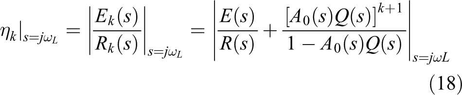
The sensitivity function of the PITR is given by


where
According to

The derivation process is described in Appendix 1. It is shown that the effectiveness of the PITR can be satisfied as long as the designed low-filter satisfies the last formula.
Analysis of the convergence and the convergence rate of the PITR
Proof of the convergence
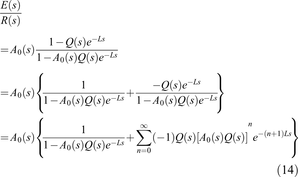
According to Figure 2, we can obtain the tracking error as

Based on (9), the expression of the tracking error in time domain can be given by

where
The formula of (12) implies the basic functional rule of the repetitive control theory. During each repetitive control period, the response of the system is a superposition of responses of several functions in time domain. Generally, in the kth repetitive control period, the time domain function ranging from
According to (b), we have

Based on the formula of (13), it can be inferred that
Analysis of the convergence rate
By transformation of the formula of (11), we obtain the transfer function of residue as
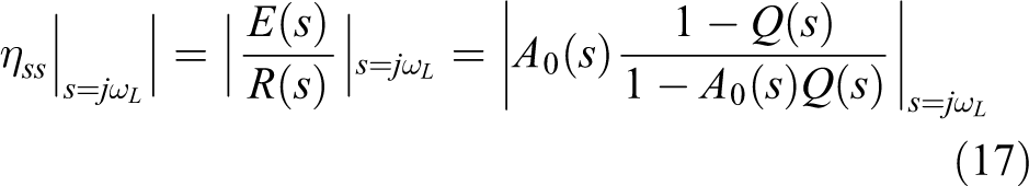
The proportion of the steady-state error of the system to the reference sinusoidal signal is

Since the reference input or the perturbation is supposed to be periodic signal, the real-time convergence residual ratio of the residual tracking error to the reference signals of the kth repetitive control period is given by
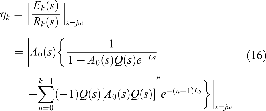

Note that the frequency of input signal is
where
Note that

The convergence rate of the PITR. PITR: plug-in type repetitive control system.
Designing and simulation
Design of the low-pass filter
To design the low-pass filter is to choose the structure of the filler and calculate the parameter under condition of (7).
First-order low-pass filter
The structure of the first-order low-pass filter is given by
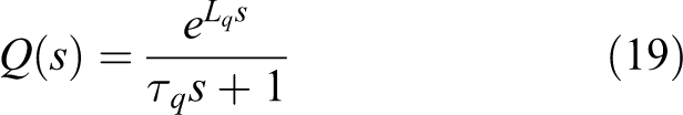
where
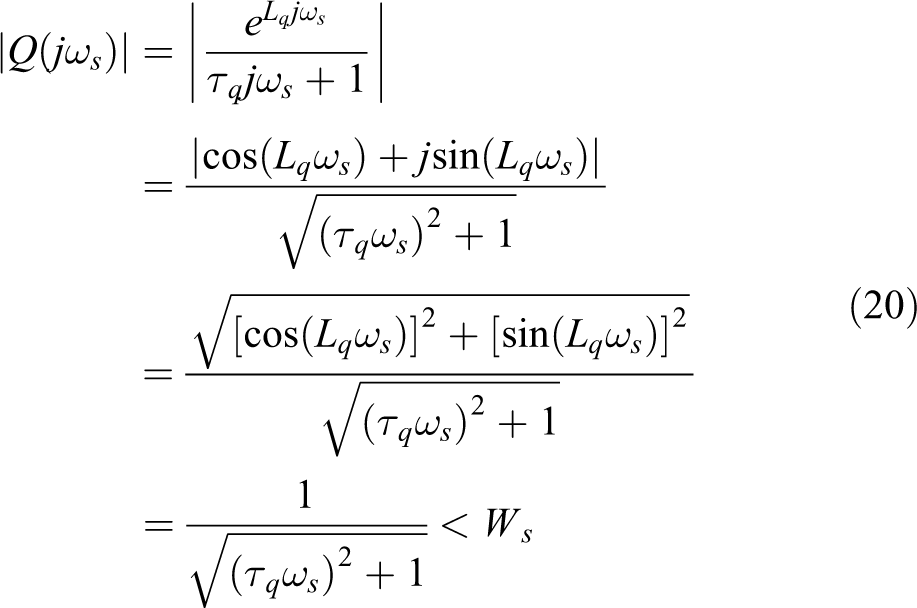
After transforming the formula of (20), we obtain
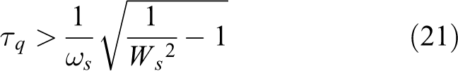
We can get the range of the value of the time constant
When designing based on the steady-state residual convergence ratio of the system, it can be obtained from (15) that

where
By solving (23), we can get the equivalent result of the designed cut-off frequency with (22). The derivation process is described in Appendix 2. The purpose of the transformation is to simplify the process of calculation and make the equation that can be solved in Matlab.

where

Second-order low-pass filter
The structure of the first-order low-pass filter is given by
where
Since the damping ratio is set to 0.707,

To ensure that the sensitivity function gets the minimum value right at the reference frequency, the selection of the leading compensation coefficient of the second-order filter should be adapted to the lag phase of the denominator. Calculate
By solving (26), we can get the equivalent result of the designed cut-off frequency with (25). The derivation process is described in Appendix 3. The purpose of the transformation is to simplify the process of calculation and make the equation that can be solved in Matlab.

where

The design algorithm for the PITR based on a steady-state residual convergence ratio
Take the second-order low-pass filter as an example to demonstrate the design algorithm. Step 1: Design the compensation controller Step 2: Plot magnitude of the sensitivity functions Step 3: Select the steady-state residual convergence ratio Step 4: The selected parameter should be examined by the results of step 2 to verify that the controller designed is reasonable.
Simulation
Take the pitch axis servo control system of a stabilized platform as the control object and set the frequency of the perturbation as 1 Hz. The identified model of the motor on the pitch axis is obtained by sweeping, and the basic stability controller is designed for the identified model to ensure the closed-loop stability of the system. The open-loop transfer function of the stable loop is given by

where
It is found that the characteristic root of the closed-loop system is
Figure 6 shows the sensitivity function of the system without the PITRC. On the top of the figure is a partial enlarged view.

The magnitude plots of
By obtaining the extreme value of the curve and its intersection with the

According to (21), the permitted range of parameters can be obtained as

which is used for the final test of validation.
The steady-state convergence residual ratio in the simulation is chosen to be 0.02%. Since the lead compensation coefficient is not determined yet, its temporary value is chosen as
Figure 7 depicts the residual convergence ratio of the PITR under the perturbation of 1Hz in the simulation, where the horizontal axis stands for the time and the vertical axis stands for the residual convergence ratio. Note that the residual convergence ratio can reach a considerable effect in the second repetition control cycle and the steady-state residual convergence ratio is about 0.0187%, which is very close to the designed index of 0.02%. The result of the simulation proves the correctness and validity of the proposed design algorithm.

Residual convergence ratio.
Figure 8 shows the comparison of spectrums of the residual convergence error before and after the insertion of the PITRC. As we can see from the figure, the origin amplitude is 4.7 × 10⁻² and then reduces to 1.867 × 10⁻⁴ in the PITR. The decreasing of value by two orders of magnitude not only shows the correctness of the design algorithm based on steady-state residual convergence ratio but also proves that the PITRC is much more effective than the traditional proportional–integral controller in suppressing the perturbation.

Spectrum of the residual convergence ratio.
Experiment
To verify the correctness of the design algorithm proposed in the third section, a physical prototype system is set up to verify the simulation results. A stabilized platform is utilized as the control object and a swing table is used to produce the perturbation to the platform. Perturbation–rejection experiments are designed to realize the certification of the simulation example and to explore the effectiveness of the design algorithm based on the index of the steady-state residual convergence ratio.
Experimental setup
Figure 9 depicts the experimental model for the PITR, where

Experimental model of PITR. PITR: plug-in type repetitive control system.
The experimental device is shown in Figure 10. The swing table provides a sine swing motion that can cause a perturbation of the same frequency to the stable platform. The DC power supplies power to the gyro, the driver, and other instruments on the platform. The dSPACE (Germany) module with the sampling time of 0.001 s is used to acquire the sensor signals and achieve digital to analog conversion. The computer and its display are helpful to the realization of the controller and the operation of the experiment. The gyro is used to sense the angular velocity of the platform around the pitch axis in the inertial space.

The experimental device.
Based on the identification model whose recognition accuracy is 87%, the PITRC of the physical prototype system is constructed using the simulation parameters calculated in the third section. The stability of the system will be verified by observing the steady-state accuracy of the system under the external perturbation of 1 Hz and the correctness of the proposed design algorithm will be verified by calculating the steady-state residual convergence ratio of the system at the frequency of 1 Hz.
Validation experimental results
To demonstrate the perturbation of 1 Hz

The time domain and frequency domain characteristics of the perturbation.
Figure 11(a) shows the actual waveform of the perturbation where the amplitude of the perturbation actually reaches 6 deg/s, while Figure 11(b) shows the feature of the perturbation in the frequency domain. It is obvious that the perturbation is dominated by 1 Hz with the amplitude of 5.746 deg/s and includes a variety of frequency components which reveal a large noise.
To calculate the steady-state residual convergence ratio of the PITR under the perturbation of 1 Hz, the lead-in compensation coefficient is set to be
The experimental results are shown in Figure 12. The waveforms of the steady-state motion residue in time domain are shown in (a), (c), and (e), while the features in frequency domain are shown in (b), (d), and (f) and the views of 0–2 Hz are enlarged in the dashed boxes. The smooth residual signals reveal that the basic stability of the system under the control of the PITRC can be guaranteed. By comparing the frequency spectrums between Figures 11 and 12, it can be found that the perturbation is greatly attenuated which reveals an excellent perturbation rejection performance of the PITR.

Time domain and frequency domain characteristics of steady-state residue. The wave forms of three experiments are shown in (a),(c) and (e). Their features in frequency-domain are shown in (b), (d) and (f) respectively.
Then, the amplitudes of 1 Hz in the frequency spectrum of the steady-state residue signal of each experiment are recorded in Table 1, which is used for calculating the steady-state residual convergence ratio of the system under the PITRC.
Steady-state residual convergence ratio.

In Table 1, the amplitudes of the 1 Hz are 1.672 × 10⁻³ deg/s, 1.921 × 10⁻³ deg/s, and 2.884 × 10⁻³ deg/s in the three repeated experiments and their steady-state residual convergence ratios are 0.0291, 0.0334, and 0.502%, respectively. Calculate the average of the data to get the average amplitude of 2.159 × 10⁻³ deg/s and the average steady-state residual convergence ratio of 0.0376%, which is slightly higher than the index of 0.02% in the design and simulation.
The main reasons for the small deviation between the measured steady-state convergence ratio and the design index are mainly due to the identification error of the control object of the stable loop and the calculation error of the spectrum of the discrete sequence. Based on the comprehensive analysis, it can be concluded that the steady-state residual convergence ratio of 0.376% in the physical prototype experiment has achieved a great deal of reach of the design index of 0.02%, and the correctness and validity of the design algorithm of the PITR based on the steady-state residual convergence ratio can be verified basically.
Conclusion
To achieve high-precision control on the stabilized platform under the periodic perturbation that usually exists in the airborne environment, a plug-in type repetitive control method is introduced. Based on the analysis of the stabilization condition, the validity condition, and convergence rate of the PITR, a design algorithm based on steady-state residual convergence ratio is proposed. The effectiveness of the design algorithm is verified by simulation where the second-order low-pass filter is designed as an example and the steady-state convergence ratio in the simulation is very close to the design index. After all, repeated physical prototype experiments are set to be an experimental verification of the proposed design algorithm. The tested steady-state convergence ratio is slightly higher than the design index and the reasons are analyzed, which verifies the correctness and validity of the design algorithm in a considerable deal.
Footnotes
Declaration of conflicting interests
The author(s) declared no potential conflicts of interest with respect to the research, authorship, and/or publication of this article.
Funding
The author(s) disclosed receipt of the following financial support for the research, authorship, and/or publication of this article: This work was supported in part by the National Basic Research Priorities Program of China (grant number A0920132001) and (17-163-11-ZT-005-034-01).
Appendix 1
Appendix 2
To simplify the calculation, omit the
Appendix 3
To simplify the calculation, omit the