
Abstract
For the purpose of solving the problem of astronaut training in weightlessness environment, this article proposes a multimodal astronaut training robot to enable astronauts to perform running, bench press and deep squat training in the weightless environment, so as to help them mitigate the adverse effects brought by the space adaptation syndrome. Taking the modularized wire driving unit as the research object, the dynamic model of the passive force servo system was established; and the passive force control strategy was designed. The experimental results show that the system is of good stability, high steady-state accuracy, and excellent dynamic quality after correction. When the given signal frequency is 10 Hz, the system phase lag is about 9°, and the loading error is about 5%. The passive force servo control strategy can effectively reduce the surplus force. When the speed disturbance frequency of carrying unit is within 3 Hz, the elimination rate of the surplus force can reach 90%.
Keywords
Introduction
The development of the manned space engineering has promoted human exploration to the universe and research on the physiological functions of human body. The results of aerospace medicine research indicate that weightlessness will cause astronauts to develop space adaptation syndrome (SAS) in the long-term course of manned spaceflight. The adaptive changes in human physiology caused by weightlessness are similar to the physical conditions of elderly people or the symptoms of long-term bedridden patients. 1 –3 If the astronauts are in a weightless environment for a long period, it may cause adaptive changes and pathological changes in the skeletal system, the muscle system, and the cardiovascular system of the human body. 4 –6 Therefore, it is of great significance to overcome the influence of SAS during the spaceflight process to ensure the safety of astronauts and to improve the working capacity of the astronauts outside the shuttles.
Physical exercise is a crucial countermeasure for astronauts to ensure good health and overcome SAS during long-term spaceflight. 7 In normal gravity environment, efficient aerobic exercises and high-intensity impedance training are designated to maintain or enhance muscle strength and bone quality. In spaceflight, aerobic training is mainly performed through equipment such as bicycle ergometer, rowing machine, and treadmill. 8 Impendence training is primarily achieved through penguin suit, interim resistive exercise device (IRED), advanced resistive exercise device, and so on. 9,10 The astronauts of the International Space Station (ISS) spend 5 h weekly running or cycling, and 3 to 6 days weekly in medium strength impedance training. 11 These pieces of training are of evident effects on resistance to muscle atrophy, decreased strength, and bone loss. However, even though the astronauts have participated in the sports training as mentioned above, muscle strength and bone quality will continue to decrease during spaceflight. As for now, the main reason for less effect of physical exercises is the lack of space training equipment and low training efficiency. The space treadmill with vibration isolation system can only provide part of the human body gravity load. Early impedance training equipment (elastic bands, IRED, etc.) can offer only limited loads. Besides, the report of the astronaut shows that even if the astronauts allocate about 2.5 h on physical exercise each day in the ISS, the training time is only 40 min (about 30% of the distribution time), and the training effect is not so satisfactory. 12
To overcome the deficiencies of the above equipment, this article will use parallel wire robot (PWR) to help the astronaut to carry out sports training in the weightless environment. The advantages of applying PWR to astronaut’s training are mainly reflected in the following aspects: (1) In the spacecraft, every single space is of great value, the modular design of PWR is easy to be reconstructed, and it can meet the requirements of lightweight, small size, safety, low consumption, and no pollution; (2) PWR can implement complex force control easily; (3) PWR adopts flexible wires as transmission elements, which can avoid rigid impact on human body and improve the training comfort; (4) the driving unit can adopt motor control, and its force control effect is better than the flywheel, pneumatic devices, and other common elastic elements, it is easy to simulate the real gravity characteristics and improve the training effects. 13,14 The structure and training model of the multimodal astronaut training robot (MAT) are shown in Figure 1.
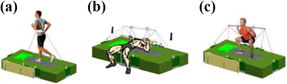
Structural scheme of the MAT: (a) Run training, (b) bench press training, and (c) deep squat training. MAT: multimodal astronaut training robot.
In the course of sports training, when the astronaut makes active motions, MAT follows the astronaut’s movements to make passive moves and add the expected load to the human body according to the astronaut’s motion state. MAT is a typical passive force servo system. The surplus force, caused by the astronaut’s active motion, is a special problem in the passive force servo system. 15 If the surplus force is large, it can seriously affect the loading accuracy.
In order to suppress the surplus force and improve the loading accuracy, the following two methods can be adopted based on the different compensation methods: (1) passive compensation method, it works effectively through mechanical structure filtering (structural compensation method) 16 ; (2) active compensation method, it is a method suppresses surplus force through control strategies (control compensation method). The structural compensation method optimizes the system structure and increases the auxiliary components. Although the compensation method has excellent stability, the system structure is complicated, and the cost is high. In contrast, the control compensation method has considerable flexibility, convenient operation, and low cost. Wang et al. adopted the speed synchronization compensation control. 17 The basic idea was to introduce a speed closed loop on the basis of the force closed loop of the original loading system to keep the loading motor and the carrying unit motion synchronously, so as to eliminate the surplus force. Jiao et al. proposed composite control based on the structural invariance principle. Its core idea was to use feed-forward control for external disturbances and to control and compensate it in advance. 18 Fang et al. proposed a compensation method based on the disturbance observer. 19 This method used a dual-loop structure: a disturbance observer was designed for the inner loop, and the controller was designed for the outer loop based on the nominal model after correction. In addition, intelligent controls, such as robust control, composite control strategy based on RBF, composite control strategy based on CMAC, have been applied in solving the surplus force. 20 In order to improve the control quality of the loading system while eliminating or reducing the disturbance, a gray prediction model combined with a fuzzy PID controller is suggested in Truong and Ahn. 21 Furthermore, fuzzy controllers and a tuning algorithm are used to change the gray step size in order to improve the control quality. The gray prediction compensator can improve the system settle time and overshoot problems. Yao et al. developed a discontinuous projection-based nonlinear adaptive robust force controller for the hydraulic load simulator. The proposed controller constructs an asymptotically stable adaptive controller and adaptation laws, which can compensate for the system nonlinearities and uncertain parameters. Meanwhile, a well-designed robust controller is also developed to cope with the hydraulic system uncertain nonlinearities. 22 The compound architecture of CMAC and PD can effectively reduce the loading error and restrain the surplus torque of electric load simulators. To overcome the unsmooth problem, Yang et al. proposed a novel scalar cost function of CMAC to guarantee fast learning capacity and improved output smoothness of CMAC. The novel CMAC-PD compound controller can effectively improve the output smoothness of the electric load simulator and eliminate the surplus torque. 23
In the above studies, both the traditional control compensation method and the intelligent control method are effective in eliminating the surplus force. Experiments also verify the effectiveness of these methods. But there is a precondition: The disturbances can be observed. For MAT, the astronaut’s motion is difficult to measure accurately with sensors. Therefore, the above methods have limitations using in MAT.
The main purpose of this article is to design a passive servo control strategy. When the frequency of the command signal is less than 10 Hz, the error between the actual load force and the command signal does not exceed 10%, and the phase lag does not exceed 10°. When the motion frequency of the carrying unit is in the range of 3 Hz, the remaining surplus force does not exceed 10%.
The rest of this article is organized as follows. The second section introduces the composition and basic working principle of MAT and wire driving unit (WDU). The dynamic model of WDU is provided in the third section. The fourth section presents the passive force control strategy. The fifth section is dedicated to providing the active loading experiments and the surplus force compensation experiments. Conclusion and future work are given in the sixth section.
Multimodal astronaut training robot
As shown in Figure 1, MAT has the following characteristics: (a) Modular design, which brings convenience to the transportation, installation, and replacement; (b) MAT can be used for multiple purposes for the symmetrical arrangement of WDUs. In the run mode, the astronaut’s pelvis is loaded by three WDUs. In the bench press mode and the deep squat mode, each end of the bar is loaded by three WDUs to simulate the gravity of the barbells.
Figure 2 illustrates the composition of the WDU. The WDU consists of a torque motor that drives a traction pulley directly. An increment encoder is located on the motor, and the encoders readings are used to determine the wire elongation. The pose state and localization of the bar or the pelvis can be further determined. A pinch roller, fixed on the side frame, is used to confine the wire to the traction pulley groove. A tension sensor is set on the other side of the frame, and a guide wheel is located on the opposite part of the tension sensor. After passing through the guide wheel, the wires motion direction changes 180°. The tension of the sensor is twice as much as the wire. Finally, the wire connects to the target after passing through a fixed guide wheel and a rotating guide wheel.

Wire driving unit.
Dynamic modeling
According to the system composition and characteristics of the WDU shown in Figure 2, the mechanism model of WDU is shown in Figure 3. The WDU transmits the load force to the astronaut through the wire. To better elucidate the effect of the wire on the system, the wire is simplified into a centralized model, that is, a mass-spring-damping model. Due to the unidirectional nature of the wire, that is, it can only be pulled and not pressed, the “mass-spring-damping” model is in a stretched state during the entire motion.
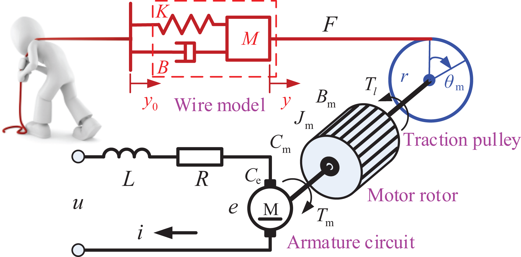
Mechanism model of WDU. WDU: Wire driving unit.
In the mechanism model of WDU: u is the motor armature input voltage; L is the motor armature inductance; R is the motor armature resistance; e is the motor armature back-EMF; i is the motor armature current; C e is the motor back-EMF constant; C m is the motor torque constant; T m is the motor driving torque; J m is the inertia of the motor rotor and traction pulley; B m is the motor armature viscous friction coefficient, T l is the motor driving torque; θ m is the angular displacement of the traction pulley; r is the radius of the traction pulley; F is the tension of the wire; y is the linear displacement of the traction pulley; M is the mass of the wire; B is the damping coefficient of the wire; K is the stiffness of the wire; y 0 is the displacement of the wire terminal.
Table 1 shows the nominal values of the parameters in the mechanism model of WDU.
Nominal parameter of WDU.

WDU: Wire driving unit.
According to the d’Alembert principle, the torque equilibrium equation of the motor rotor and traction pulley is

where the drive torque
The armature circuit equation of the DC torque motor is

where
The force equilibrium equation of the mass-spring-damping model is

Besides


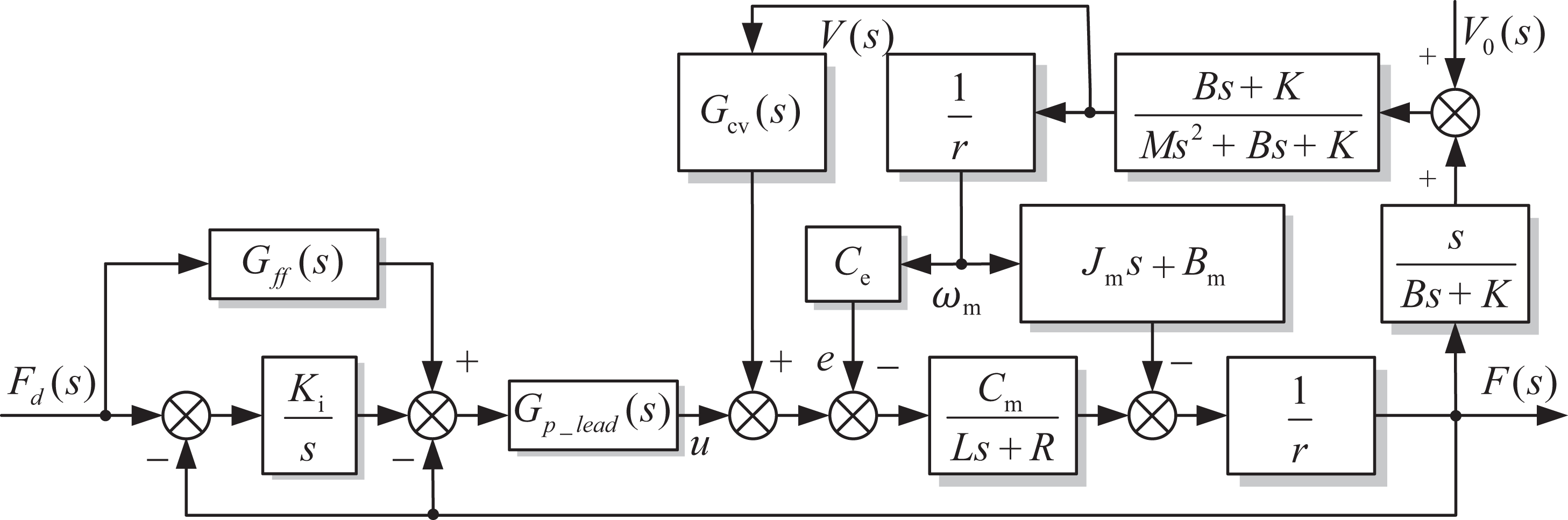
According to the equations (1) to (5), the block diagram of the open-loop wire driving force servo system is shown in Figure 4 on considering the influence of the carrying object motion. Two inputs affect the output wire traction F. One is the motor armature voltage u, the other one is the speed disturbance v
0 introduced by the movement of the carrying object,
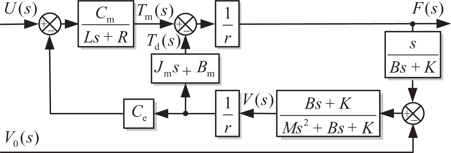
Block diagram of the wire driving loading system.
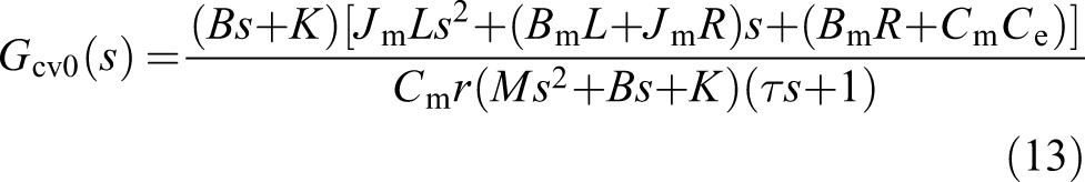
From Figure 4, under consideration of the influence of the motion of the carrying unit, the transfer function of the wire driving passive force servo system is

M 1(s) is the transfer function from the input voltage u to the output F. It’s the transfer function of forward channel
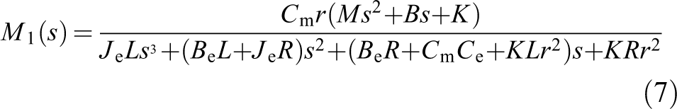
M 2(s) is the transfer function from the input speed disturbance v 0 to the output surplus force F. It’s the transfer function of disturbance channel

In equations (7) and (8),
Passive force control strategy
Based on the theoretical model of the WDU, the control strategy of the wire driving passive force servo system is determined as: (1) to ensure the loading accuracy and rapidity, an active loading control strategy needs to be designed by correcting M 1(s); (2) to minimize the surplus force, the surplus force compensation strategy should be developed.
Active loading control strategy
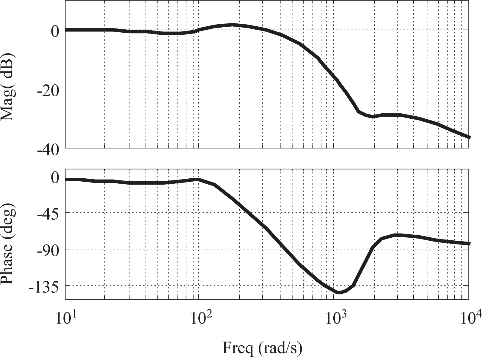
Figure 5 is the frequency response of the forward channel. In the low-frequency range, the amplitude frequency response curve of the system is straight enough without correction; the phase frequency response exhibits hysteresis characteristics, the system phase lags approximately 35° at 10 Hz (62.8 rad/s).
Bode diagram of the forward channel transfer function.
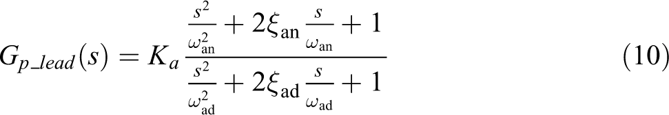
As can be seen from equation (7), the forward channel of the WDU is a zero-type system, which cannot ensure the loading accuracy. Meanwhile, due to the influence of hysteresis characteristics, the dynamic performance of the system loading is poor. The design of the active loading control strategy needs to take into account the accuracy and rapidity of the system. The block diagram of the active loading control strategy is shown in Figure 6. The main feedback controller uses integral control. Its primary role is to improve the system’s steady-state accuracy. The local feedback correction link Gp _ lead (s) adopts the second-order phase lead correction link for local correction, and its main function is to compensate for the lack of dynamic quality of the passive object. The feed-forward correction link Gff (s) cooperates with the local feedback correction link Gp _ lead (s) to improve the rapidity of the system. In addition, Gbs (s) is a double-T band-reject filter for the feedback channel. Its stop-band frequency range is 45 Hz to 55 Hz, ξ is the measured noise.


Active loading control strategy of WDU. WDU: Wire driving unit.
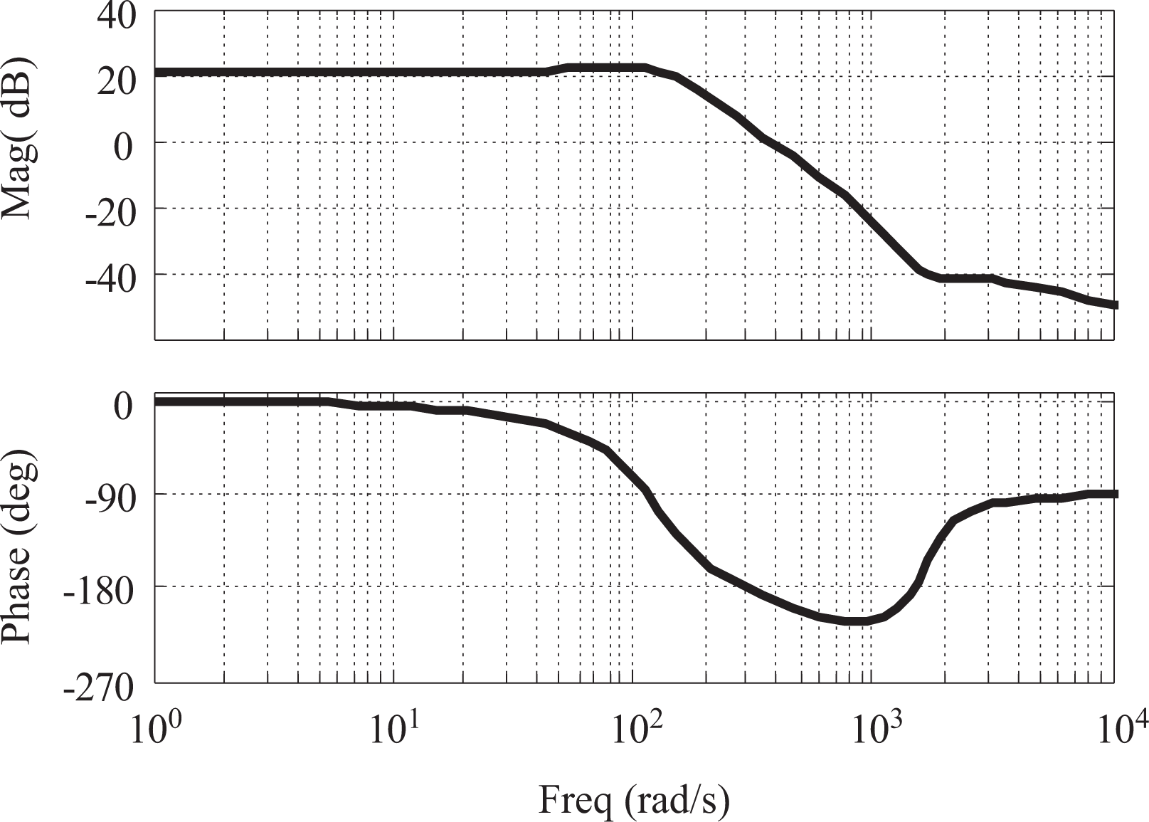
The closed-loop frequency response of the corrected system is shown in Figure 7. The steady-state error of the system after correction is small. The phase lag of the system after correction at 10 Hz (62.8 rad/s) is about 8°.
Closed-loop frequency response after correction.
Surplus force compensation
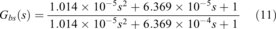
Figure 8 is the frequency response of the surplus force transfer function. It can be seen from the figure that, due to the influence of the first order differential link, the magnitude of the surplus force increases with the increase of the speed disturbance frequency and the phase slightly ahead of the speed disturbance. When the frequency of input speed disturbance exceeds 126 rad/s, due to the second order oscillation link, the magnitude of the surplus force will decrease with the increase of the of the speed disturbance frequency. The phase of the surplus force lags behind the speed disturbance, and the phase lag is no more than 90°.
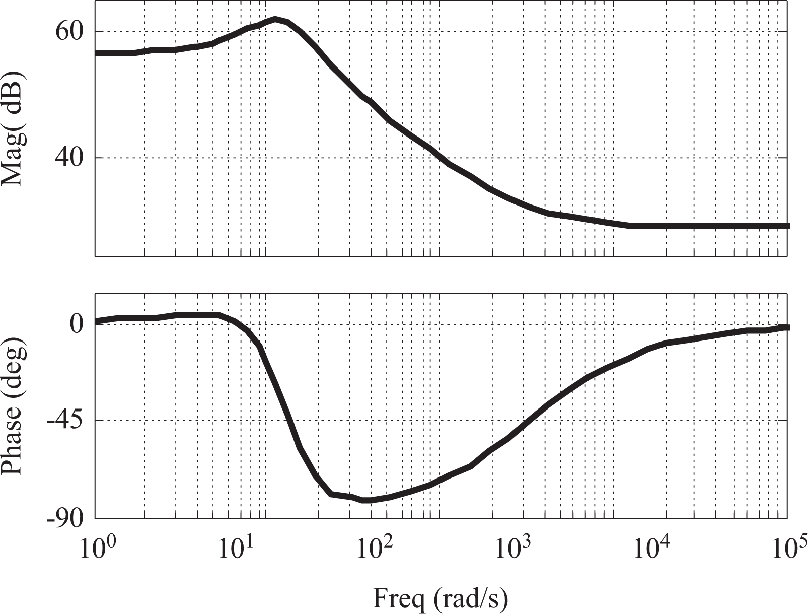
Frequency characteristic of the surplus force transfer function.
To verify the accuracy of the surplus force transfer function, the characteristics of the surplus force were further studied through the experiments. The WDU is an open-loop control system. By inputting a constant voltage, the cable is tensioned and maintains a constant tension of 150 N. The deviation of actual force from expected force is mainly caused by the speed disturbance, that is, the surplus force. In order to ensure the stability and safety, the maximum input speed is 0.1 m/s, and the input speed is reduced to 0.05 m/s when it’s frequency is 40 Hz. The experimental results are shown in Figure 9. The statistical results of the experiment are shown in Table 2.
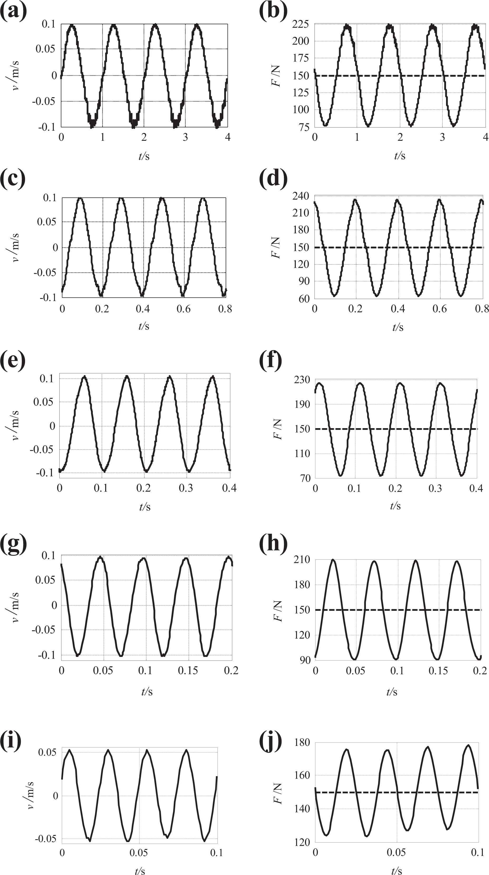
The surplus force of the cable driven unit at different speed.(a) 1 Hz speed disturbance, (b) 1 Hz surplus force, (c) 5 Hz speed disturbance, (d) 5 Hz surplus force, (e) 10 Hz speed disturbance, (f) 10 Hz surplus force, (g) 20 Hz speed disturbance, (h) 20 Hz surplus force, (i) 40 Hz speed disturbance, and (j) 40 Hz surplus force.
The surplus force of the wire driven unit.

According to the experimental results, the frequency characteristic of the actual surplus force is basically consistent with the frequency characteristic of the theoretical model. Therefore, based on the theoretical model of surplus force, the dynamic characteristic of the surplus force in the actual system can be qualitatively analyzed, and then the compensation strategy of the surplus force can be designed.
According to the structural invariance principle, an observable disturbance quantity needs to be found in the system and then set up a feed-forward compensator to compensate the influence of the interference. The block diagram of the control principle is depicted in Figure 10.
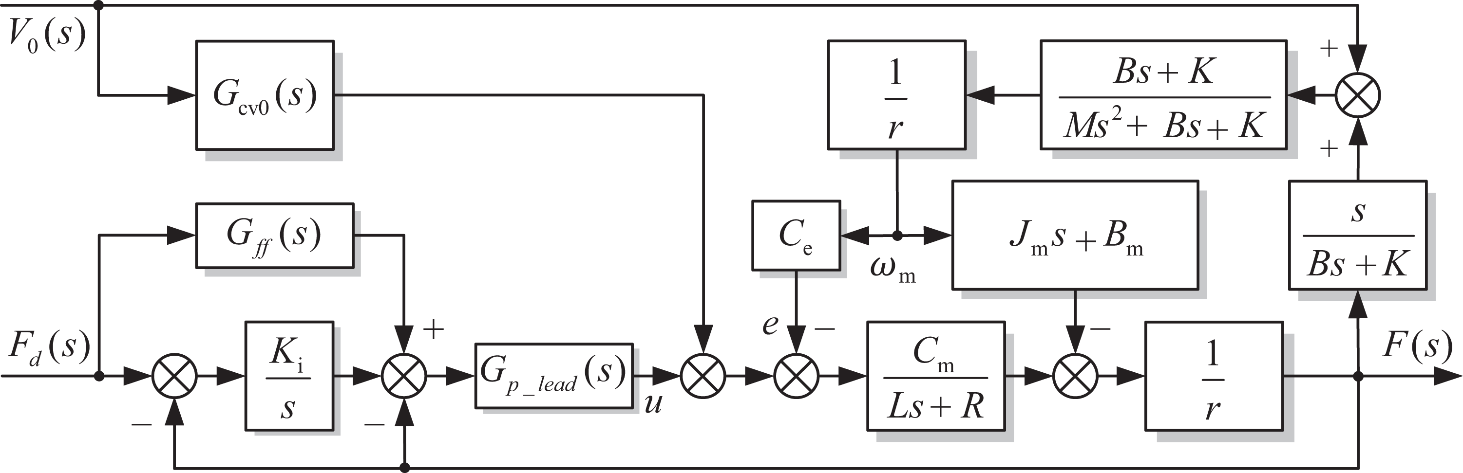
Block diagram of the control system compensated by the object speed.
According to the equation (6), the surplus force is formally generated by the carrying unit speed v 0 through the transfer function M 2(s), the influence of the interference is directly applied to the output of the WDU. Therefore, it is the most direct and effective way to use the carrying unit speed v 0 to compensate for the surplus force. If v 0 can be directly measured, the compensation transfer function is
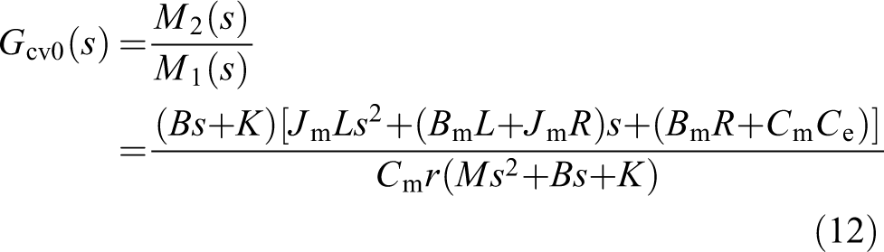
In practical applications, the order of the compensation link in equation (12) is higher than that of the denominator and has differential characteristics. Considering the physical availability, a pole must be configured in the denominator. The approximate compensation transfer function is
The premise that the disturbance compensation control strategy designed in Figure 10 can eliminate the surplus force is that the disturbance (the motion of the carrying unit) can be observed. However, for the WDU, the object it carries is the human body, and its motion is of great uncertainty and difficult to be estimated. Therefore, it is difficult to compensate for surplus force by observing the speed v 0 of the carrying unit. Considering that the stiffness of the wire is relatively large, the motion speed v 0 of the carrying unit and the towing speed v of the WDU can be regarded as to be approximately equal at the low-frequency band. The control principle block diagram of the disturbance compensation using the tow speed of the WDU is shown in Figure 11
Block diagram of the control system compensated by the tow speed.
In Figure 11, v is the wire tow speed, which is the linear speed of the wire traction pulley, and ω m is the angular speed of the torque motor. The tow speed v can be measured and converted by the optical encoder in the WDU. For the disturbance compensation control strategy designed in Figure 11, as long as the compensation it produces is the same as the disturbance compensation control strategy designed in Figure 8, then this compensation strategy is effective and therefore, it must satisfy equation (14)

And due to v 0 ≈ v

Considering that the load target of the WDU is the human body and the frequency of human body motion does not exceed 3 Hz in the specified training modes, it is feasible to use the wire tow speed v to perform the disturbance compensation. 24,25 For the phase lag of the tow speed v relative to the speed of the carrying unit v 0, it is necessary to correct the compensation link to improve the compensation effect.
Experiment study
Active loading experiment
To further demonstrate the effectiveness of the proposed active loading control strategy, the experimental study of the active loading control was carried out. In the process of experiment, the end of the wire was fixed. In other words, there was no speed disturbance in the system. Since the wire could only withstand the pulling force, the pre-tensioning force of the wire in the initial case was 150 N. The expected force varied periodically with the time. The frequency was 5 Hz and 10 Hz, respectively, and the amplitude was 20 N. According to the actual response of the system during the experiment, the parameters of each part of the composite controller were adjusted and finally determined as shown in Table 3.
Parameters of active loading controller.

The active loading effects are shown in Figure 12. When the given signal is 5 Hz, the system phase lag is about 7°, and the actual load force amplitude is almost not attenuated. When the given signal frequency is 10 Hz, the phase of the actual force lag about 9°, and the actual force amplitude decays 0.45dB approximately. The active loading controller of the WDU meets the design requirements.
Tracking curve of the hybrid control (dotted line: expected force; solid line: actual force). (a) 5 Hz and (b) 10 Hz.
Surplus force compensation experiment
To verify the effectiveness of the surplus force compensator, the surplus force compensation experiment was carried out. The experimental platform is shown in Figure 13. The carrying unit is a speed servo system that performs the active motion. The loading unit is a force servo system that passively follows the carrying unit and loads the expected force on the carrying unit. The encoder signal of the loading unit was collected, and the surplus force was compensated by the motor speed of the loading unit.
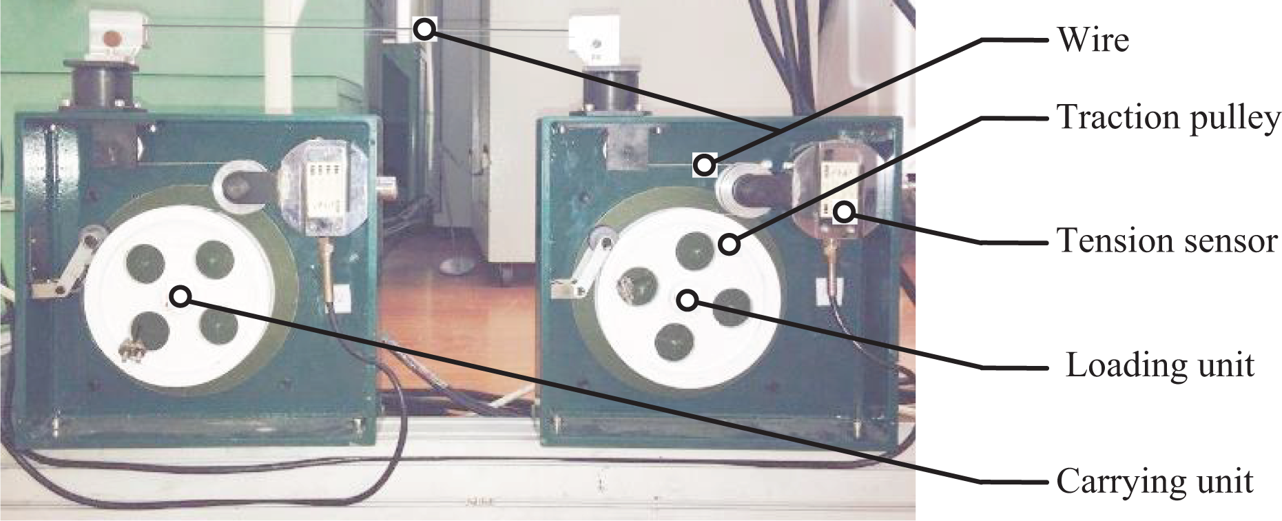
Experimental platform for passive loading.
In equation (15), the time constant of the filter link is 0.01. By further observations, it can be found that the compensation link after adding a filter link has a pair of zero (ω n = 108.2 rad/s) and pole (ω d = 100rad/s) to constitute a dipole. The zero and pole can counteract each other to avoid the negative effect of the amplification noise. At the same time, there is a real zero (corner frequency ω n = 3333 rad/s) far from the imaginary axis in the compensation link. This first-order differential link only compensates for high-frequency interference which is far more than the normal operating frequency of the system. Therefore, this zero can be ignored during the actual controller design and experimentation. Based on the above analysis, equation (15) is modified, and the transfer function of the modified surplus force compensation component is
The theoretical compensation link is composed of a proportional link, a first-order differential link, and a second-order oscillation link. The parameters of the theoretical compensation link are shown in Table 4. K is the gain of the proportional link. ω n is the corner frequency of the first-order differential link. ω d and ξ d are respectively the natural frequency and the damping ratio of the second-order oscillation link. In the experiment process, the turning frequency and damping ratio of the compensation link can be adjusted so as to improve the compensation effect.
Parameters of surplus force compensator.

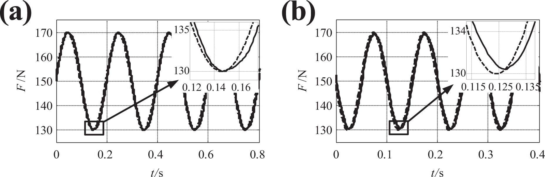
During the experiments, the control parameters of the surplus force compensation link were adjusted. The parameters of the surplus force compensator are finally determined as shown in Table 4. When the speed amplitude of the carrying unit is 0.3 m/s and the motion frequency changes from 1 Hz to 6 Hz, the experimental results of the passive force control experiments are shown in Figure 14. The expected force loaded on the carrying unit is 150 N indicated in Figure 14 by dotted lines. The solid line represents the actual loading effect. The deviation of actual force from expected force is mainly caused by the movements of the carrying unit, that is, the surplus force. The statistical results of actual system surplus force elimination rate are shown in Table 5. The experimental results show that the designed passive force control strategy can effectively reduce the surplus force.
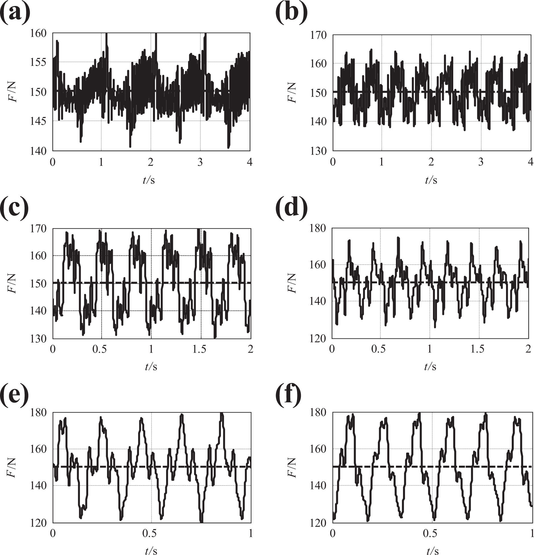
The surplus force of the WDU with different frequency speed disturbance input. (a) 1 Hz, (b) 2 Hz, (c) 3 Hz, (d) 4 Hz, (e) 5 Hz, and (f) 6 Hz. WDU: Wire driving unit.
Statistical results of the surplus force compensation experiments.

Conclusion
Focusing on the current state of the astronaut sports training equipment with single function and poor training effects, this article proposed a MAT to enable astronauts to perform multiform sports trainings (running, bench press, and deep squat) in the weightless environment, so as to help them mitigate the adverse effects of SAS. Taking the WDU as the research object, the dynamic model of the wire driving passive force servo system was established. On this basis, the passive force control strategy was designed, and corresponding experiments were conducted. An active loading controller was designed. The experimental results show that the corrected system has good stability, high steady-state accuracy, and excellent dynamic quality. When the given signal frequency is 10 Hz, the phase lag is about 9°, and the loading error is about 5%. In addition, a surplus force compensator was designed. The experimental results show that the surplus force compensator can effectively reduce the surplus force. The elimination rate of the surplus force can reach 90% when the moving frequency of the carrying unit is less than 3 Hz. As part of our continuing work, we are working on further improving the stability of the system and making full preparation for man-machine experiments. We will also play the advantage of the reconfigurability of PWR to expand the training modes. The passive loading control strategy needs to be optimized to reduce the effect of surplus force further.
Footnotes
Declaration of conflicting interests
The author(s) declared no potential conflicts of interest with respect to the research, authorship, and/or publication of this article.
Funding
The author(s) disclosed receipt of the following financial support for the research, authorship, and/or publication of this article: This work was supported by the National Natural Science Foundation of China under Grant 51705534, the Fundamental Research Funds for the Central Universities under Grant 18CX02085A, the Shandong Provincial Natural Science Foundation under Grant ZR2016EEB12, the Key Scientific Innovation Project of Shandong Provincial under Grant 2017CXGC0902, the Hubei Provincial Natural Science Foundation under Grant 2018CFB313, and the Hubei Superior and Distinctive Discipline Group of “Mechatronics and Automobiles” under Grant XKQ2019053 and XKQ2019002.