
Abstract
In this article, we address a formation control problem for a group of autonomous robots to track a moving target in the presence of obstacles. In the proposed method, desired formations, which consist of virtual nodes arranged in specific shapes, are first generated. Then, autonomous robots are driven toward these virtual nodes without collisions with each other using a novel control scheme, which is based on artificial force fields. The convergence analysis is shown based on Lyapunov’s stability. The novelty of the proposed approach lies in a new combination of rotational force field and repulsive force field to design a mechanism so that robots can avoid and escape complex obstacle shapes. The effectiveness of the proposed method is illustrated with numerical examples using V-shape and circular shape formations.
Introduction
Research activities in multiagent systems have offered a wide range of applications in various areas such as physics, biology, cybernetics, and agriculture. In the field of multiagent systems, one of the most important problems is formation control, in which agents in the system are required to form desired shapes. Typical potential applications in formation control include search and rescue missions, forest fire detection and surveillance, source seeking, and so on. Autonomous robots of a multiagent system can be underwater vehicles, 1,2 unmanned aerial vehicles, 3,4 mobile sensor networks, 5 –12 rectangular agents, 13 and nonholonomic mobile robots. 14 –18
Centralized control protocols have been constructed based on the common assumption that the information of all agents is available or the multiagent system possesses all-to-all communication. The drawbacks of the centralized communication control architect are inflexibility and large computational costs for each controller for each agent especially when the number of robots is large. In contrast, a distributed or decentralized control approach can provide more flexibility, easier implementation, and less computation loads as the controller of each agent only requires the information of its neighbor agents. 6,7,18 –21
In formation control of a multiagent system, desired tasks of the system, such as tracking a moving target, are executed by the cooperation of a robot team. The formation control problem of autonomous robots is motivated by natural behaviors of creatures such as fish schooling, bird flocking, or ant swarming. Here, the members in the formation are required to collaborate with others to achieve common goals such as velocity matching and collision avoidance. The formation of a swarm of mobile robots can be generated and controlled by different methods in the literature. It is well-known that the artificial potential field method plays a pivotal role in controlling the coordination and the motion of a swarm so that its agents move toward target positions. 22 –28 It is well established that the potential field generates impulsive/attractive forces for mobile robots to avoid collision and maintain distances in coordination control problems. 5 Many works on the formation control method using the random connections among neighboring members in a swarm as an α-lattice configuration were reported in a variety of papers. 5 –12,29,30 In this direction, the attractive/repulsive force fields are employed to link neighboring robots so that a robust formation without collisions is established. In a different approach, a dynamic framework was introduced by Hou et al. 31 and Cheah et al., 32 in which the robots of a swarm can adapt their formation by rotating and scaling during their movement. Similarly, the attractive/repulsive force fields were also utilized by Eren 33 to control robots to converge to given positions of a desired shape.
Although the artificial potential field has been regarded as a powerful tool for path planning of mobile robots, it still possesses some limitations due to local minimum problems. This can lead to a situation where a robot can get stuck if facing with an obstacle. In this context, the attractive force of the target and the repulsive force of the obstacles are equal and collinear but in an opposite direction. As a result, the total force on the robot is equal to zero, which traps the robot there. In addition, the traditional potential field method exhibits shortcomings in complex environments which contain convex and concave obstacle shapes, such as U-shaped obstacles or long walls and so on. When facing with these kinds of obstacles, robots can be trapped in them, and hence prevented from reaching targets. 34 The summary of related work is shown in Table 1. Recent research methods were proposed to address local minima avoidance 41,42 that the reader can refer to.
Summary of related work in multiagent formation control.

LCF: α-lattice connection formation; DFF: dynamic framework formation; FS: formation following desired shape.
In many studies, the dynamics of agents are modeled as single integrator, 13,43,44 double integrators, 5,7,10,45,46 and unicycles. 47,48 In narrow space, the shapes of agents are taken into consideration for the formation control problem. 13,44 In this article, a formation control problem for point-based agents with double-integrator dynamics is addressed. Theoretical development of the paper sets a framework, which can be employed to design a formation control system for various agents with more complicated dynamics and shapes. The particle model in this article has been extensively used in previous work. The work of Olfati-Saber 5 presents a theoretical framework for design and analysis of distributed flocking algorithms using the double-integrator dynamics for the dynamics of an agent. In applications, it is employed to model mobile robots that have omnidirectional motion capability, such as the Rovio mobile robots. 7,10 It is also used in theoretical work for mobile sensor networks. 45,46
The main contributions of this article are in the following. The formation control algorithms are designed to drive multiple robots to converge to the desired positions to capture a moving target while avoiding collision with other agents and obstacles. However, the communication is still all-to-all since there is a need to compare the distances of agents to the target to choose the leader of the swarm. Once the leader is chosen, the control law of an agent is calculated based on the positions and velocities of its neighbor agents. In this case, the control algorithm is distributed, which helps save computational costs. The stability of the formation is maintained and collision avoidance among robots is obtained while the swarm tracks a moving target. In addition, the novelty of the article lies in the combination of the rotational and repulsive force fields, from which the obstacle avoidance control algorithm is constructed to drive robots to escape obstacles without collisions.
The structure of the article is organized as follows. In section Formulation, the problem formulation is presented. In section Control algorithms, the formation control algorithms are presented. Section Case study presents a case study for two typical examples of V-shape and circular shape formation control. Section Simulation results presents some simulation results. Finally, section Conclusion concludes the article with some remarks and future research topics.
Problem formulation
In this article, a swarm of N robots is considered with their mission of tracking a moving target in two-dimensional space. Let
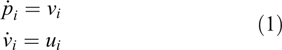
for
Conditions for a formation of autonomous robots are as follows: There are no collisions among robots. Robots must converge to the desired positions. Robots must avoid collision with obstacles. The formation must be maintained under the influence of the environment.
A desired formation of a multi-robot system consists of virtual nodes which will be occupied by the robots of the system. To facilitate the control design and analysis, we introduce the following definitions.
Definition 1
In the desired formation, a virtual node j (
Definition 2
Let

Description of the formation control method using the desired V-shape and circular shape structure. Agents use algorithm 1 to reach their virtual nodes to form the desired formations. The leader is selected by using algorithm 2.
Definition 3
Let l denote the index of the current leader of the swarm.
Definition 4
In the desired formation, virtual node j is called an active node if a robot i (
Definition 5
The desired V-shape formation consists of two line formations. These line formations are driven by a selected leader and connected by a formation angle ϕ. In each line of the formation, the virtual nodes are equidistant to its neighboring ones.
Definition 6
The desired circular shape formation is a circle in which all virtual nodes are distributed evenly on the circle and the target lies in the center of the circle.
Definition 7
Let

where
Definition 8
A set of the neighboring obstacles of robot i at time t is defined as

where
Control algorithms
This section presents control algorithms to guarantee that all robots will converge to their desired positions in the desired formation. While tracking a moving target, collision and obstacle avoidance of the swarm must be achieved.
Control architecture
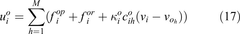
To address our problem, we propose the control input

where
Formation connection control algorithm
Initially, there exists an attractive force field for each virtual node j
In algorithm 1,
Theorem 1
Consider the active robot i with its dynamic model (1) and control input
Proof
In order to analyze the stability of the robot i at the active node j when the node

Consider the vector field

Equation (6) shows that the vector field

Taking the negative gradient of the function

Equations (6) and (8) show that the vector field
Let


where
where
Remark 1
It is well established that the Lyapunov theory is employed for the stability proof of formation and flock control of multiagent systems. 5 For more information about the Lyapunov theory, the reader is referred to the work of Freeman and Kokotovic 49 and Khalil. 50
Remark 2
Figure 1 illustrates a desired formation (V-shape or circular shape formation) of N virtual nodes. The desired formation contains a desired position for each robot. Algorithm 1 allows each free robot i to firstly seek its closest free virtual node (for instance, j) so that it will be active at this virtual node. If the position of an active robot i is still not at the desired one (e.g. robot k in Figure 1 with
Reaching the desired positions at the virtual nodes in the desired formation.
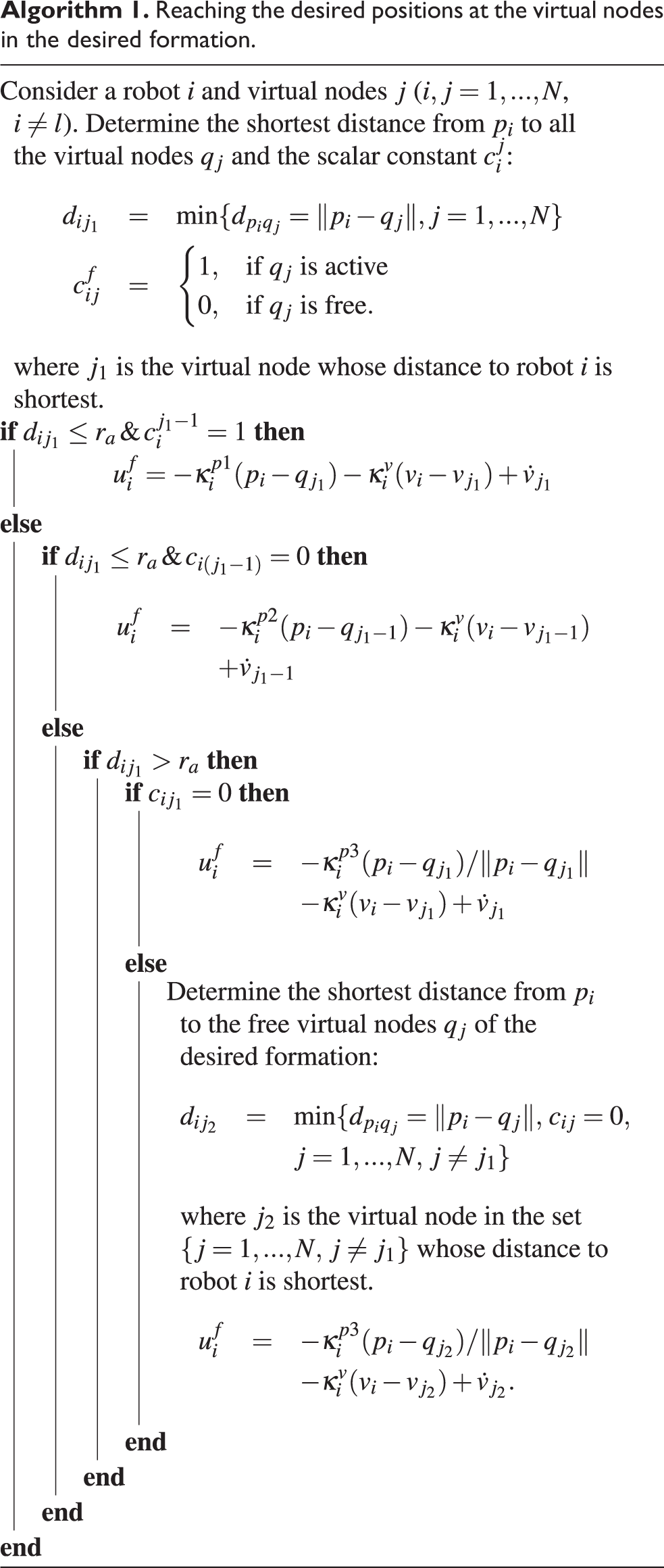
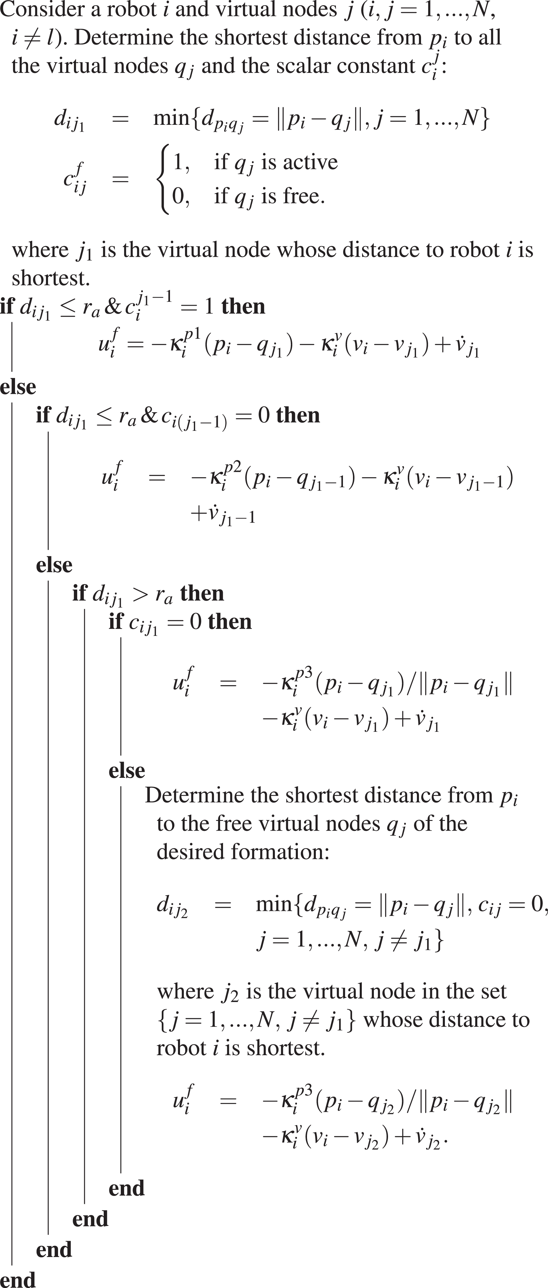
In order to allow robot i to approach node j as fast as possible, we use the attractive force from node j, which is proportional to its velocity. This means that the factor

where
Collision avoidance control algorithm
This section presents a method for the collision avoidance among the robots during their movement based on the artificial repulsive potential field. The potential field has been widely used in addressing flocking and formation control of multiagent systems.
5,9,22
–24
In general, a potential function
In order to avoid the collision between robots i and k (i,

where positive constants

The algorithm for the collision avoidance is built based on the repulsive vector field (14) combined with the relative velocity vector

The controller (16) reveals that neighboring robots are controlled to leave each other when distances among them are too close. As in the study of Olfati-Saber, 5 we employ repulsive fields to avoid collision among agents. The analysis is quite similar to that in the study of Olfati-Saber. 5 Therefore, our control mechanism guarantees that collision avoidance in the swarm is achieved.
Obstacle avoidance control algorithm
This section presents a control algorithm for robots to pass through M obstacles. The obstacle avoidance control algorithm for each member robot i (
where relative velocity vector

The repulsive force field

where positive factors

The description of the repulsive force field
In control law (17), the rotational force field (see Figure 3) is added to combine with the repulsive force (see Figure 2) to drive robot i to quickly escape its neighboring obstacle. While the potential force field is used to enable it to avoid collision with its neighboring obstacle, the rotational force field is used to solve the local minimum problems; for instance, the robot meets a trapping point, at which the repulsive force of the obstacles and the attractive force of the target are balanced. Under the effect of the added rotational force field, the robot always escapes this trapping point. Furthermore, when robot is trapped in complex obstacles (e.g. U-shape or long wall), the rotational vector field will help it find a new path to escape these obstacles. The direction of the rotational force can be clockwise or counter clockwise (see Figure 3). Hence, this rotational force is built as

where the unit vector

where the scalar
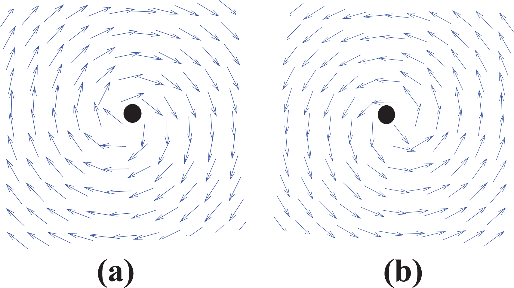
The clockwise rotational force field (a) and the counter clockwise rotational force field (b).
Let σ be the angle between these vectors. Then, we have

Equation (22) shows that the unit vector is always perpendicular to vector

where

where

where two constants

The description of the obstacle escape of a robot i while reaching a virtual node j: clockwise (a) and counter clockwise (b).
The total vector for the control law for agent i is
The obstacle avoidance analysis of the proposed scheme follows a similar approach as in theorem 6 in the technical report by Olfati-Saber. 51 Unlike the method of Olfati-Saber, 51 in our method, when an agent meets an obstacle, a rotational force field is generated which changes total force field. Hence, the direction of the agent is turned around the obstacle.
We summarize the above analysis in the following theorem.
Theorem 2
Consider the active robot i with its dynamic model (1). If robot i detects an obstacle in its obstacle detection range as in Figure 4, the control law in equation (17) will drive robot i to escape the obstacle.
Remark 3
The protocol for collision avoidance for the agents of the system in subsection Control architecture employs a repulsive force in equation (14). Here, the shapes of agents are simplified to be points or circles. In contrast, the obstacle avoidance in this section is realized using repulsive and rotational forces in equations (19) and (20) for a class of complex obstacles (which can be large and nonconvex). This enables agents to escape the obstacles effectively. The constraint posed on a nonconvex obstacle is that the radius of the osculating circle of the obstacle is larger than
Remark 4
The complex obstacle used in our analysis is in a U-shape, which is nonconvex (see Figure 4). A rigorous study would be conducted to see whether our obstacle avoidance approach can work with a more general class of complex obstacles in the future.
Target tracking control algorithm
Firstly, a robot, which is closest to the target, is selected as the leader in order to generate the desired formation. Then, this leader leads its formation to track a moving target. When the leader encounters a risk, such as it is broken or trapped in obstacles, it must transfer its leadership to another, and becomes a free member robot in the swarm. The leader is selected as in algorithm 2.
The target tracking controller, which is designed based on the relative position between the leader and the target, has to guarantee that the formation’s motion is always driven toward the target. As introduced above, the V-shape and circular shape formations are utilized to track and encircle a moving target. Hence, the tracking task is to make the distance between the leader and the target

where
The potential field from the target is used to drive the leader moving toward the target, and is given by

where
Theorem 3
Consider the leader l described by model (1) and governed by control law (26) when
Proof
Firstly, we consider the vector field
Equation (28) shows that the vector field
Consider the scale function

Taking the negative gradient of

Hence, equations (28) and (30) show that the vector field
In order to analyze the stability of the leader at the equilibrium position, at which


From equations (26) and (31), we have


To analyze the stability of the system (33), we choose the following Lyapunov function candidate

Taking the time derivative of equation (35) along the trajectory of the system (33), we obtain

According to LaSalle’s theorem,
Remark 5
The formation of the swarm changes with respect to the relative position between the leader and the target. Initially, a robot will be chosen as a leader to lead its formation toward the target if it is closest to the target. During the motion of the swarm, if the current leader faces any risk (for instance, it is broken from the formation or hindered by the environment), then a new leader is nominated. Algorithm 2 guarantees that this new leader will reorganize the formation and continue to lead the swarm to track the target.
Leader selection.


Remark 6
Obstacles in the environment can be sensed by several methods. Onboard sensors of each agent can detect them. In addition, hybrid approaches can employ a group of aerial drones to capture the images of obstacles and agents and transfer data to the agents. 19,20
Remark 7
The paper 53 addressed the swarm tracking problem to capture a moving target in a specific formation using artificial potentials and sliding mode control. The dynamics used in this work are fully actuated. The artificial potentials are used for the formation and tracking control goals. Sliding techniques are used to deal with uncertainty, which exhibits robustness of the proposed control method. The control framework by Yao et al. 53 was then applied for agents with nonholonomic dynamics by Gazi et al. 54 Our control strategy shares the same principle as in the studies of Yao et al. 53 and Gazi et al. 54 where artificial potentials are employed for formation and target tracking control. On the one hand, the work of Yao et al. 53 and Gazi et al. 54 considers robustness issues, which we do not address in this article. On the other hand, our article deals with collision and obstacle avoidance, which are not included in the article. 53,54
Case study
The proposed algorithms as discussed in the previous section can allow the robots to follow predefined formations such as V-shape, circular, or line shape. Due to their similarity, we just present two cases of V-shape and circular shape. Let
V-shape formation
Firstly, in order to build the V-shape desired formation, we design the right side of this V-shape based on the desired formation angle

where the angle


The description of the method to build the V-shape desired formation.
From base node

Now, a virtual node j (

Here, d is the distance between any two consecutive virtual nodes. Note that

Equation (41) can be rewritten as

Equation (42) shows that when j changes from
Similarly, the virtual node j on the left side of the V-shape is designed as

where

where

Using equation (45), we obtain the formation of the virtual node j. They lie on the line through

where


The description of the distributed virtual node j in the desired V-shape formation (a) and in the desired circular shape formation (b).
where
Circular formation
As presented above, the circular formation is used to encircle the moving target when the distance between the leader and the target is shorter than the target approaching radius
The position of the virtual nodes j (

The position of the virtual node j on the coordinate system

Let the virtual node owned by the leader be the first position in the circular desired formation. Substituting equation (49) into equation (48), we have the circular formation of the virtual node j as follows

Equation (50) shows that the distributed virtual nodes j (
Simulation results
In this section, we use the V-shape and circular desired formations, which are built in section Case study, to illustrate the proposed control algorithms. We assume that the initial velocities of the robots and the target are zero. The initial positions of the robots are random. Each robot can sense the position of other robots within its sensing range as well as the positions of the target and obstacles. The target moves in a sine wave trajectory, which is defined as
Parameter values.

Achievement of desired formation
For this simulation, the formation angle is selected as
The results in Figure 7 show that the desired formations were easily created. Robots, which have random initial positions, quickly achieved the desired positions in these desired formations while tracking a moving target without collisions. The position permutations among the members in the formation appeared, but they did not influence the structure of the formation when tracking the target. As shown in Figure 7, at the initial time, one robot was chosen as the leader to drive its formation toward the target in a V-shape formation. At time t = 70 s, the V-shape formation was constructed, and it was kept until the square robot detected the obstacle

The evolution of a swarm following the desired formations under the influence of the dynamic environment while tracking a moving target.

The distance between the leader and the target in case the leader is not hindered while tracking a moving target.
Next we consider the connection of a swarm when the leader was trapped in the complex obstacle (e.g. U-shape obstacle; see Figure 9). In this situation, the actual leader had to transfer its leadership to other members in the swarm, and managed to escape this obstacle. Figure 10 shows that, at time t = 0 s, the square robot was chosen as the leader, and its leadership was kept until it was trapped in the U-shape obstacle at time t = 200 s. While avoiding obstacle, the square leader transferred its leadership to the triangular robot, which was not faced with any obstacles and closest to the target. Then, this square leader became a free robot. It automatically found a way (lilac way) to escape this U-shape obstacle in order to continue following its formation.

Path planning for a swarm following the desired formations while tracking a moving target with the leader permutation.
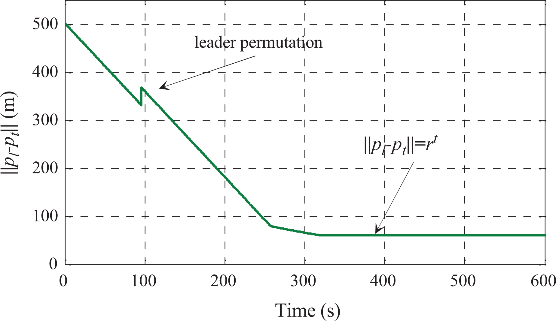
Distance between the leaders while tracking a moving target in case the leader is permuted.
After receiving the leadership, the triangular robot reorganized a new formation and continued to lead this formation to track the target. The distance between the new leader and the target shrunk until it achieved the active radius of the circular desired formation
The robustness of the swarm in noisy environment
In this subsection, we examine the robustness of the formation under the influences of noise and the change of the formation angle. Distances and velocities of agents are affected by noises, whose profiles are the Gaussian function with zero mean and variance of 1 (see Figure 11). The formation angle

Measurement noise.

Formation angle
Figure 14 shows that robot i was always close to active node j in the desired formation, and its formation was maintained following the desired formations (V-shape and circular formation) under the influence of the noisy environment and the changes of the formation angle

Position errors

The influences of noises and the different formation angles on the swarm’s trajectory while tracking a moving target.
Conclusion
In this article, a new method for decentralized formation control of autonomous robots has been presented, in which the swarm tracks a moving target in a dynamic and noisy environment. The robot system can form predefined formations such as V-shape or circular shape while avoiding collisions among agents of the swarm. The new mechanism which combines the rotational and the repulsive forces can drive robots to quickly escape complex obstacles such as those with concave shapes. The theoretical analysis of the proposed algorithm is given. In our future research, the proposed approach would serve as a framework for addressing the formation control of multiagent systems in two-dimensional space such as unmanned aerial vehicles and underwater robots.
Footnotes
Authors’ note
The views, opinions, findings, and conclusions reflected in this publication are solely those of the authors and do not represent the official policy or position of the USDOT/OSTR, or any State or other entity.
Declaration of conflicting interests
The author(s) declared no potential conflicts of interest with respect to the research, authorship, and/or publication of this article.
Funding
The author(s) disclosed receipt of the following financial support for the research, authorship, and/or publication of this article: This work was partially supported by the National Aeronautics and Space Administration under grant number NNX15AI02H issued through the NVSGC-RI program under sub-award no 19-21, the RID program under sub-award no 19-29, and the NVSGC-CD program under sub-award no 18-54. This work was also partially supported by the US Department of Transportation, Office of the Assistant Secretary for Research and Technology (USDOT/OST-R) under grant number 69A3551747126 through INSPIRE University Transportation Center (![]() ) at Missouri University of Science and Technology.
) at Missouri University of Science and Technology.