
Abstract
Advanced motions, which utilize footholds on walls, offer considerably more opportunities for hexapods in accessing confined environment. However, there has been no research on the practical application of such motions on a hexapod. These motions are kinematically viable for the standard hexapod design with three degrees of freedom per leg but the joint requirements have yet to be identified. This article presents the motion analysis for two forms of advanced motion, wall walking and chimney walking, to study the joint requirement for executing such motions. The analysis has been verified through a series of experiments demonstrating that a hexapod with a standard design is capable of executing advanced motions.
Introduction
The advantages of legged robot locomotion over other types of propulsion have been widely discussed in the literature 1 –3 and have inspired competitions that try to replicate real-world scenarios where legged robots could be deployed for inspection and intervention missions. The DARPA Robotics Challenge (natural/man-made disasters), 4 ARGOS (oil and gas refineries) 5 and Eurathlon (urban and indoor environments) 6 all provide demonstration areas to test the state of the art in legged locomotion.
All of the challenges mentioned above are largely concerned with two-dimensional (2D) motion, and navigating around obstacles that are, at most, of the same scale as the robot. Specifically, the areas being traversed accommodate the footprint of the legged robot. For example, doorways or stairwells are wider than the robot trying to navigate passed them. What has not been considered in any depth is the challenge of non-planar motion in cluttered spaces. Figure 1(a) shows the example of a hexapod manoeuvring through a gap that is narrower than its footprint by using the vertical surfaces of the gap to provide support. Figure 1(b) shows how three-dimensional (3D) motion can be achieved in certain situations.

Advanced motions exploiting the robot’s full mobility for navigation through: (a) narrow space by wall walking and (b) a large hole by chimney walking.
This article is concerned with non-planar hexapod manoeuvres, which will be termed advanced motions and the scenarios shown in Figure 1 will be considered in detail. 7 The movement shown in Figure 1(a) is termed wall walking and that in Figure 1(b), chimney walking. Such manoeuvres have not previously been considered in the literature.
The motions shown in Figure 1 are likely to impose additional requirements on the joints of a hexapod relative to two-dimensional manoeuvres. The aim of this article is to identify the effect of key design parameters on joint requirements for executing advanced motions. In particular, the relationship between the robot’s link lengths and motion plan and the joint requirements will be considered. It should be clearly understood that the work is based on a hexapod of standard design, and a key element is to investigate the extent to which an ‘off-the shelf’ hexapod is capable of executing advanced motions.
This rest of this article is organized as follows: First, the current state of art on typical hexapod motions and joint characterization approaches for hexapods are presented. Next, the joint requirements analysis for advanced motions is detailed followed by the mechanical design of the particular hexapod used in this work (Corin). The validation experiments and their results are then detailed. The final section concludes the work and an outlook to future work is detailed.
Related work
This section consists of two parts: the first provides a brief overview of typical hexapod movements, while the second provides an overview of link and joint selection approach for hexapods. The nomenclature used in this article is specified in Figure 2.

Summary of nomenclature for hexapods. Leg labels: odd number legs are on the left side (
Typical hexapod movements
The motion of a hexapod consists of two phases: the transfer phase, where a leg is transferred from one foothold to another, and the support phase, where the legs supporting the robot’s mass move the body in the desired direction. 1 In virtually all cases, footholds are confined to the support (ground) surface. Footholds on irregular terrains such as grass 8 or rocks 9 can still be thought of as lying on the ground surface. 10 This generalization can also be applied to inclined surfaces since, from a kinematic perspective, slopes have no effect on hexapod movements.
A small number of additional movements have been considered that utilizes non-ground (wall) surfaces. These are the climbing strategy used for surmounting large obstacles 11 and moving through a narrow pathway with the aid of a semi-elliptical shell attached to the robot’s back. 12 However, the use of wall surfaces is limited relative to what is proposed here.
Link selection and joint characterization for hexapods
The key design parameters of a hexapod are its base width and length and the lengths of its leg links. These affect the joint requirements in terms of the range of motion, velocity and torque, and these in turn affect the design parameters. This results in a large number of interdependent parameters that must be selected during design. To reduce the parameter search space, a common approach is to first select the design parameters followed by the joint requirements or vice versa.
The selection of design parameters uses bio-inspired, pragmatic or optimization-based approaches, and sometimes a combination of approaches. Bio-inspired approaches base design choices on living creatures. 13 –15 Pragmatic approaches may, for example, base design decisions on the characteristics of the target deployment environment 14 or on the torque limitations of the intended actuators. 16 Optimization-based strategies may consider energy consumption, 17 mobility 18 or dexterity 19 as the optimization metric.
Joint characterization of hexapods typically uses either static analysis 13 or motion simulation, 8 often with predefined link parameters. However, in the literature, both parameter selection and joint characterization are only ever considered in the context of two-dimensional manoeuvres. Clearly, an important consideration when considering non-planar hexapod motion is to consider how this affects link selection and joint characterization. In the next section, static analysis of advanced motions will be studied, in order to gain an understanding of the effect of design parameters on joint characterization. This will then allow the selection of appropriate design parameters and actuators for a hexapod capable of advanced motions.
Design analysis
The effect of key design parameters on joint requirement for a hexapod with a standard design to execute advanced motions needs to be studied. This would enable the selection of actuators given the key design parameters, or vice versa, that meets the joint requirement for such motions. The key design parameter of interest here is the body width and leg’s link length, while the joint requirement is the maximum torque and range of motion required. This section characterizes both the motions of interest in this study (Figure 1) and studies the effect of link length and body width on joint requirement.
Static analysis setup
The analysis of motions is based on the following assumptions: The motions are discretized and semi-static. The motion occurs only in the y-z plane (see Figure 3). The total mass of the robot is assumed to act at the geometrical centre. The tangential force lies on or within the friction cone edge. The foot contact forces for multiple support legs on a single side are distributed equally for each leg.

Summary of nomenclature for this analysis. Link labels: lumped body width (
From the second assumption, the robot model is simplified to have only two legs with two degrees of freedom (DoF), as shown in Figure 3. Gaits that have two support legs on either side of the robot are lumped together as a single leg for the force distribution analysis (discussed shortly). The coxa link,

The two characteristic motions considered here are called wall transition (Figure 4(b)) and chimney walking (Figure 4(a)). The wall transition, which refers to the motion of the robot rearing up sideways towards a wall, is analysed as a precursor to the analysis of wall walking (Figure 1(b)), as the demand on joint torque will be higher due to the longer horizontal moment arm between the robot’s geometrical centres to its feet.

Illustration of the discretized motion sequence (from left to right), starting from ground to the final stance for (a) wall transition and (b) chimney walking. Each discretized motion is called a pose, numbered accordingly as
The body pose,

where

where
Force distribution
The contact force,
Wall transition
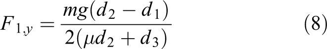
The worst case scenario is when the robot uses the tripod gait where only one support leg is on the ground plane, while two support legs are in contact with the wall plane. Based on the sum of forces of the robot and moments at point B in Figure 4(a)-3


where m is the robot mass, g is acceleration due to gravity and
For no slip to occur, the tangential force for the legs in wall contact was selected to lie on the friction cone edge

Substituting equation (7) into equation (6) yields
and the rest of the contact forces are


Chimney walking
The torque demand for chimney walking is large, which is evident in the HyQ platform. 20 Hence, it is assumed that the robot has a minimum of four support legs to reduce the joint torque demand. With four legs in support (two on each side), the tangential force distributed evenly across each leg is

and the minimum normal force required to prevent slippage on each leg is

Joint angle requirement
The maximum joint angle requirement is when the leg needs to move from ground to wall contact at its most constrained position, that is, the leg is tucked in as close as possible (Figure 10). The initial position of the foot is constrained structurally and will be identified following the selection of the link length for
Force distribution parameters
The parameters for the force distribution analysis are shown in Table 1. The ‘*’ implies that these parameters are dependent on link length parameters. The equations for these are available in Appendix 1.
Parameters for the force distribution analysis.

The lumped body width and body mass were assumed according to small-scale hexapods. 7 A conservative μ was selected given the high friction observed from using rubber feet. 20
The three parameters of interest in this study are the overall width,

The range selected has been based on the required leg work envelope of at least 0.2 m. The link ratio,
The step size, β, is the resolution in which the parameters
The wall contact foot height,
Results and discussion
The joint requirements and energy cost for these two characteristic motions were computed in MATLAB. The three parameters of interest,
The results for the peak torque requirement among any of the joints,

Energy and torque requirement for the wall transition and chimney walking.
Effect of parameters of interest
From Figure 5, increasing
For chimney walking,
Effect of fixed parameters
The effect of the environment parameters, namely

Torque and energy requirement at

Torque and energy requirement at
For wall transition, the change in
The result of the force distribution from equations (8)
to (10) changes according to the moment arm length to the left foothold, which is dependent on
The E generally increases with
For chimney walking,
The effect on the selection of
From an optimization perspective on energy consumption, there is no global minimum for both wall transition and chimney walking. E for chimney walking is at a minimum when
Corin platform
This section briefly presents the mechanical design of the Corin hexapod, as shown in Figure 8, that is agile and versatile for multi-legged research in advanced motions.

CAD image of Corin equipped with LiDAR and visual sensors.
Hardware design
A rectangular body shape has been selected since this results in the smallest footprint width for wall and chimney walking compared to the hybrid or hexagonal shapes (

Comparison of rectangular with hybrid/hexagonal shape for sideways walking.
The standard insect leg consisting of three DoFs has been employed for its larger workspace compared to parallel manipulators. The hip consists of two joints: the coxa,
To enable force/position control, a three-axis capacitive force sensor has been attached to each foot enabling 3D contact force measurement. The rubber feet provide high friction and damping to reduce slipping and impact forces.
Link parameter selection
Since the joint actuators were selected first, the link parameters were chosen to achieve objectives of ensuring that the joint torque requirement of the characteristic motions lies within the selected actuator constraint 16 and maximizing the robot’s mobility. 18
The use of E for selecting link length is not considered as there is no minimum that coincides for both wall transition and chimney walking. The joint torque constraint limits the parameter selection to
Within the link ratio range for
Following on from the selection of the link ratio, the joint angles corresponding to the first wall contact foot position for wall transition have been identified to be

Joint angle requirements for moving the leg from ground to wall when the leg is tucked in. The red arrow line indicates the discretized instance, n, of the foot path.
The length of
System overview of the Corin hexapod.

DoF: degree of freedom.
Validation experiments
The Corin platform has been developed, both in terms of simulations and real implementation, as a vehicle to explore the ability of a hexapod of fairly conventional design to implement non-planar hexapod motions. In this initial investigation, the focus has been on the ability of the hexapod to adopt static poses and semi-static motions that are typically part of the transitions between floor and wall/chimney walking (see Figure 11). The limitations of this approach are understood; nevertheless, this quasi-static evaluation provides important basic information about the requirements on a hexapod that is intended to perform non-planar manoeuvres.
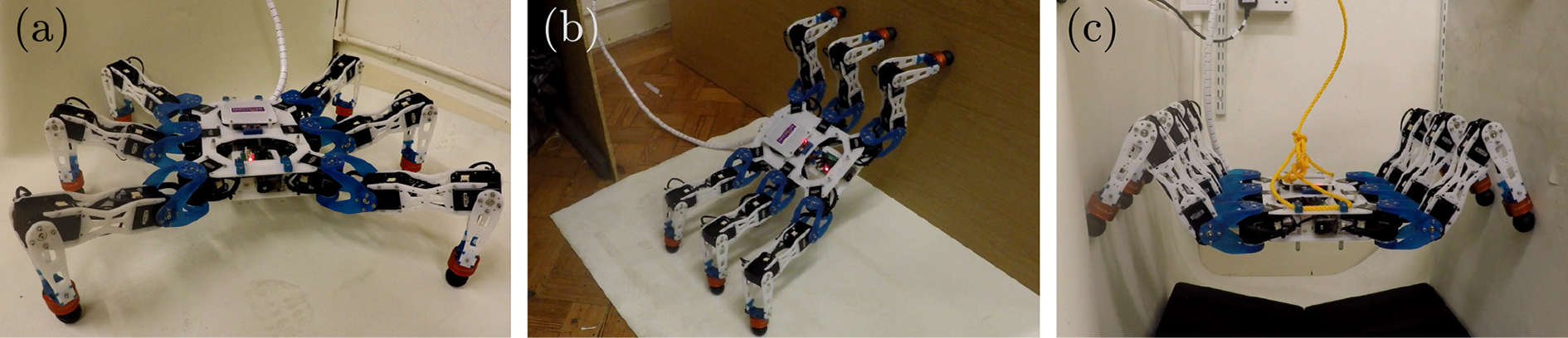
(a) Corin hexapod, evaluated for (b) wall transition and (c) chimney walking motions.
Experimental configuration
A physical implementation of Corin has been developed and subjected to a program of testing in simple non-planar scenarios. The robot was powered through an external 12 V supply via an umbilical. This reduced the total weight of the vehicle, which was measured to be 4.6 kg. The environmental surfaces used in the experiments were either plain wood or rubber mats. The friction coefficients for these two surfaces combined with Corin’s rubber feet were estimated to be 0.83 and 0.87, respectively. This range is encompassed by the design analysis presented in the earlier section.
The robot was evaluated in terms of its capability to maintain static poses and execute statically stable motions for both wall and chimney walking. In the former case, the robot was positioned in selected transitional poses and the number of support feet was gradually reduced from six to three for a wall transition and from six to four for chimney walking. This shows that the robot is able to retain its static pose, in accordance with the design analysis presented earlier.
In each of the selected poses, the robot was required to translate 0.05 m along each of the three axes, with six legs in support. This ensures that non-planar movements can be achieved using discontinuous phase gaits. The motions were evaluated in open-loop mode, and so there was no active regulation of the body orientation. The joints were controlled using the actuator’s onboard position controller.
Each evaluation was repeated three times. Table 3 lists the parameters of the robot pose and leg positions, with respect to the leg frame. In the wall transition experiments, the robot’s pose was measured relative to the floor-wall boundary. For chimney walking, the robot was positioned in the middle of the chimney, and its static pose observed for a number of chimney widths, each differing from the previous width by 0.05 m.
Parameters for wall transition and chimney walking motions.

Results
Wall transition
Figure 12 shows the position tracking of leg 4; support legs were removed at times 5 s (leg 2), 10 s (leg 3) and 15 s (leg 6). The current drawn by leg 4’s femur (see Figure 2) servo is also shown in Figure 12.
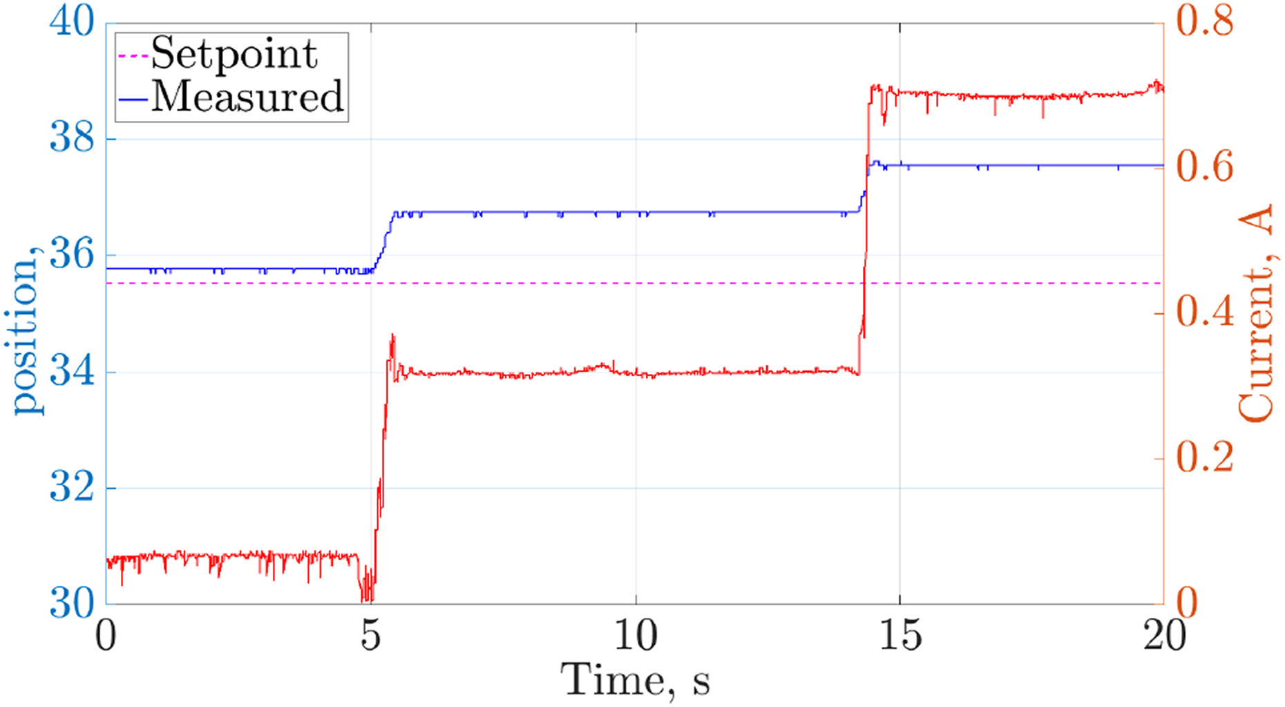
Position tracking and current of leg 4 femur joint when the number of support legs decreased during the transition pose.
It can be deduced that leg 3 provided limited support for the robot, as there was minimal change to leg 4’s joint position and current draw when it was lifted up at
For the evaluation of the motion, the robot tracked a continuous path with 3D translations (see supplementary video for static poses and semi-static motions). The currents drawn by all the robot joint actuators were well below the stall current limit (see Figure 13). Low PID gains were used with the joint controllers in the absence of higher level controllers to avoid large internal forces. This resulted in a slight degradation of position tracking with a maximum error of 4°, but this is considered to be well-within acceptable bounds. Hence, it can be concluded that the robot is able to execute the wall transition manoeuvre.
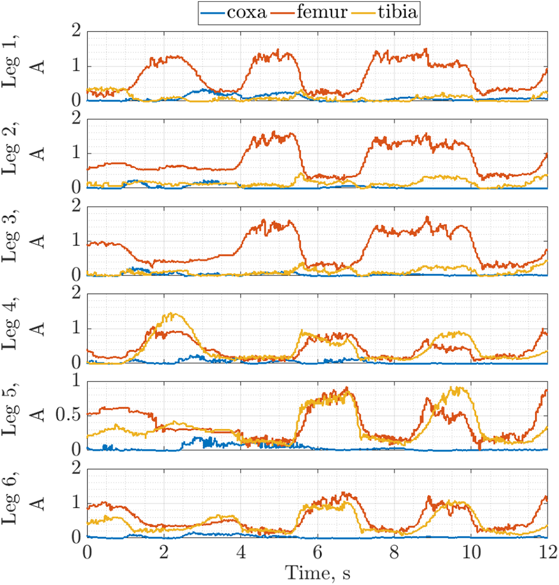
Joint current for all six legs executing motions representative of the wall transition motion.
Chimney walking
In the chimney walking experiments, the Corin hexapod was able to maintain its position when legs 1 and 6 were lifted off the walls (Figure 14). It tilted forward slightly when leg 1 was lifted as the contact forces generated by the five remaining supporting legs caused a moment about the robot’s centre of the mass. Due to symmetry, the initial tilt was removed when leg 6 was lifted. The contact forces did not generate any noticeable moments since there was no observable change in the robot’s orientation.

Corin maintaining static position by supporting itself between two walls with (a) six legs, (b) five legs and (c) four legs. The red circles indicate the leg removed from support.
Figure 15(a) and (b) shows the joint tracking and the current drawn by each of the servos controlling the robot’s leg 4 joints. Joints

Joint tracking and current for motions representative of chimney walking motion. (a) Joint tracking for leg 4. (b) Joint current for all six legs.
Comparison with other approaches
Three approaches of characterizing joint torques that have been reported in the literature 8,13,25 were applied to Corin. Table 4 shows the results obtain from these approaches. The result from the analysis presented earlier in this article is included for comparison.
Comparison of joint torque using different characterization approaches.

The approaches from the literature are used to obtain torque-demand bounds for two-dimensional hexapod motion that is confined to a ground plane. The three different approaches all show that
A limitation of this work is that only static and semi-static manoeuvres are shown. However, these are precursor to the full manoeuvre which requires high-level controllers with force feedback and torque control. 20 Since the robot here currently utilizes position controllers only, it is thus limited to only static and semi-static movements. Future work will address the development of the controllers necessary for achieving the full motion.
Conclusion and future work
This article has presented a static 2D analysis of advanced hexapod manoeuvres, specifically wall and chimney walking. The analysis shows the relationship between link parameterization and joint torque demand. The joint range of motion has also been identified as part of this analysis. The analysis has been used to select the link parameters for the Corin hexapod, which generally assumes the design of well-established hexapods. The two forms of advanced motion have been validated experimentally with a real Corin hexapod. The work shows that hexapods of fairly standard design are capable of advanced manoeuvres, so long as suitable link length and joint actuators are properly selected. The ability of hexapods to execute such advanced manoeuvres enables them to explore areas previously deemed inaccessible.
It has been observed in the experiments that the use of position control leads to situations where the robot momentarily loses its balance. This can be addressed through the use of a high-level controller that distributes foot force equally (using torque and foot force feedback). Furthermore, the use of low-level controllers on each leg, such as impedance controller, allows robust operation on irregular surfaces, reducing the computation burden on the high-level controller.
Footnotes
Declaration of conflicting interests
The author(s) declared no potential conflicts of interest with respect to the research, authorship, and/or publication of this article.
Funding
The author(s) disclosed receipt of the following financial support for the research, authorship, and/or publication of this article: This work was supported by UK Research and Innovation through the Engineering and Physical Science Research Council under grant numbers EP/R026084/1 and EP/P01366X/1 and Innovate UK (KTP009811 and project no. 131777).
Supplemental material
Supplemental material for this article is available online.
Appendix 1
References
Supplementary Material
Please find the following supplemental material available below.
For Open Access articles published under a Creative Commons License, all supplemental material carries the same license as the article it is associated with.
For non-Open Access articles published, all supplemental material carries a non-exclusive license, and permission requests for re-use of supplemental material or any part of supplemental material shall be sent directly to the copyright owner as specified in the copyright notice associated with the article.