
Abstract
Intervention missions, that is, underwater manipulation tasks, for example, in the context of oil-&-gas production, require a high amount of precise, robust navigation. In this article, we describe the use of an advanced vision system suited for deep-sea operations, which in combination with artificial markers on target structures like oil-&-gas production-Christmas-trees significantly boosts navigation performance. The system is validated in two intensive field tests running off the shore of Marseille, France. In the experiments, a commercial remotely operated vehicle equipped with the system and a mock-up structure with an oil-&-gas production panel is used to evaluate the navigation performance.
Keywords
Introduction
In recent years, there has been an increasing interest in autonomous behaviors for intervention missions, that is, missions with autonomous underwater vehicles (AUVs) or at least semiautonomous remotely operated vehicles (ROVs), which include automated, machine-controlled manipulation tasks. 1 –9 Surveillance and inspection missions are usually not so critical in terms of navigation performance. For these missions, the vehicle observes the environment only from a distance and the localization accordingly needs to be only reasonably accurate. Also, post-processing of the data with, for example, simultaneous localization and mapping or even with manual correction of outliers by an end user is a common practice. But intervention missions in contrast have higher demands on the navigation. Especially, the vehicle is by definition closer to objects of interest that need to be manipulated—precise and robust localization in real time is hence of high interest.
We present here work on the use of artificial markers to improve navigation in the context of intervention missions. Concretely, ArUco markers 10 are used. This is motivated by the fact that intervention typically takes place in environment settings that involve man-made structures, for example, Christmas-tree installations in the context of oil-&-gas production (OGP), where the markers can be easily added before deployment of the structures. The idea to exploit man-made structures for navigation in the context of intervention can also be found, for example, by Evans et al., 9 where edges extracted by computer vision are matched against a priori known 3-D CAD models of the structures. Visual markers have also been used before in underwater applications, for example, in a form of active light beacons for docking. 11 In the work presented here, augmented reality (AR) markers are used, which are in general designed to provide good identification and localization capabilities. AR markers have among others been used underwater for their original purpose, that is, for AR by displaying virtual objects and virtual scenes into a diver’s view of the real world at the location of the markers, 12 for example, to assist divers in commercial operations 13 or to enable underwater games for divers. 14 AR markers have also been used to enable a diver to communicate with an AUV 15 and for the identification of nodes in an underwater sensor network. 16 Last but not least, AR markers have also been used in the context of navigation, for example, for the visual servoing of an ROV on a moored target 17 and the detection and localization of panel elements for intervention. 18
The work presented here is done in the context of the EU project “Effective Dexterous ROV Operations in Presence of Communications Latencies (DexROV)”. 19 DexROV deals with the problem that the state of the art for underwater manipulation is dominated by costly ROV operations, which require an offshore crew. This crew typically consists of at least an intendant, an operator, and a navigator. And it often has to be duplicated or even tripled due to work shifts enabling 24/7 operations for, for example, missions in OGP. Furthermore, intervention is still dominated by low-level, manual control of the manipulator(s) and of the vehicle itself. The core idea of DexROV is to enable operations from an onshore control center. This includes among others a reduction of the gap between low-level teleoperation and full autonomy. The user in an onshore control center (e.g. in Brussels, Belgium in our field trials) interacts with a real-time simulation environment, and a cognitive engine analyzes the user’s control requests and turns them into movement primitives that the ROV needs to autonomously execute in the real environment (e.g. in the waters off the shore of Marseille, France, in our trials). One challenge for this operation scheme is the communication latencies of the satellite link between the control center and the vessel.
The contributions of our work on navigation aided by AR markers presented here are among others (a) the use of a novel underwater calibration method and of image enhancement methods to improve marker detection and localization, (b) additional measures with respect to the view angle and distance range to increase the robustness, and most importantly (c) a significant amount of system development and integration leading to a high technology readiness level (TRL) of six suited for field trials in realistic application conditions (Figure 1), especially with respect to a wide range of challenging visibility conditions.

Our navigation system has been employed at a high TRL of 6. It was tested, for example, in two extensive field trials off the shore in Marseille. In addition to the vision system to aid the navigation (left), the setup in these trials consists of an Apache ROV extended a dual arm setup, which is deployed from the COMEX Janus II vessel (center). A mock-up panel structure is used to test different application scenarios (right). TRL: technology readiness level; ROV: remotely operated vehicle.
The system components
The core navigation system
Our core navigation system is based on a standard, state-of-the-art approach, namely, the use of a Doppler velocity log (DVL) and an inertial measurement unit (IMU). Concretely, a Navquest 600P micro DVL and a Xsens MTi-300 IMU are used. The DVL is rated for up to 6000 m depth, that is, it is suited for deep-sea operations. The DVL is mounted on the bottom of the DexROV-skid, which is added to the Apache ROV in the field trials. The IMU is integrated into the compute bottle of the vision system, which is also integrated on the skid. The DVL is directly connected to the compute bottle.
The DVL provides altitude as well as velocities in X, Y, and Z (speed over ground), which is used for the computation of the translation. The IMU is used to track the ROV orientation. As described in more detail later on, a standard approach is used for the processing of the data for the core navigation system, namely, an extended Kalman filter (EKF). This processing is handled by the vision computer in the onboard compute bottle, which is described in the next section.
Vision system components
State-of-the-art ROVs like the Apache used in DexROV often rely on analog camera systems. However, the image quality is strongly influenced by the connection to the support vessel. Due to long cables used in deep-sea operations, images are noisy and there can be interrupts in the streams, which makes processing of the data by computer vision quite challenging. The use of digital cameras has multiple advantages, especially when they are combined with computation power on the vehicle to generate an intelligent vision system. First of all, an intelligent underwater vision system (Figure 2, 3 and 4) can be used to minimize the traffic over the umbilical cable from the ROV to the vessel. Especially, it allows to online adapt the image resolution, the compression factor, and the frame rate to optimally use the available bandwidth for the task at hand. Furthermore, computer vision can be used directly onboard of the ROV to assist core capabilities, like navigation in the work presented here, up to the provision of autonomous functions. This processing onboard of the ROV minimizes latencies and increases robustness compared to processing on the vessel, which requires the transmission of sensor data over the limited data connection of a tether up to the vessel and also the sending of commands down to the ROV again.

The camera system consists of a computer bottle with significant online processing power to which multiple cameras in pressure housings can be daisy-chained (left), for example, as a stereo setup with two cameras (right).

The camera pressure housing of one camera of the intelligent underwater camera system.
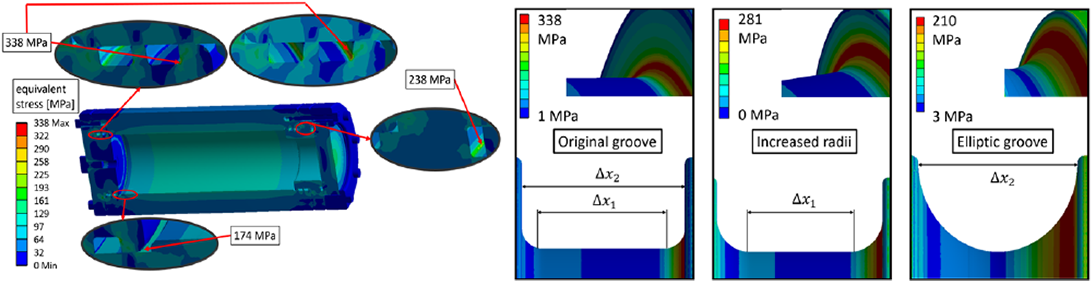
The design of the pressure housings for the cameras and the compute bottle are optimized by numerical simulations.
Our intelligent vision system is based on high-resolution firewire (IEEE 1934b) cameras in pressure housings. Concretely, Point Grey Grasshoppers2 cameras are used. They are based on Sony ICX285 CCD sensors, which are known for good performance in lowlight conditions. The firewire bus signals are relayed over high-frequency underwater cables between the bottles to allow the daisy-chaining of multiple cameras connected to an embedded computer, which is used for vision processing and for adaptive video compression onboard of the ROV. For the onboard vision computer, which also services the core navigation based on the DVL and the IMU, an Intel NUC with a 4th-Gen Intel Core i5-4250U is used. The firewire bus supports among others the synchronization of the cameras. They can hence be used for stereo, respectively, multi-camera setups to generate depth information from different views with a known relative geometry. The option of more than two synchronized cameras allows implementing different baselines to cover different range/resolution trade-offs in one system. Due to payload constraints of the Apache ROV, a stereo setup with two cameras is used in all field trials.
The camera bottles are equipped with flat Sapphire glass windows. All bottles designs are optimized by numerical simulations for 4000 msw and pressure tested in the real world for deep-sea operations up to 2000 msw. The cameras need to be calibrated intrinsically and extrinsically with respect to the ROV platform. For intrinsic calibration, own work is used, 20 which allows calibrating the system in air, prior to underwater deployment with no need of further in-water calibration. The predicted camera parameters take salinity, temperature, and pressure into account, so the varying depth of the application can easily be taken care of. This is facilitated by a new camera model dubbed PinAx as it combines an axial and a pinhole camera model. 20 Based on the calibrated camera model, the images from both cameras are rectified to remove the distortions, which stem from the refraction caused by the water and the protective glass panel in front of the cameras. This contributes to the robust recognition and localization of the AR markers. Furthermore, several pre-processing steps are executed to enhance the image quality. Especially, own methods to reduce haze are used in this context. 21,22
System operation
For the onboard vision system, reliability and robustness are of high interest. Furthermore, the network connection through the tether between the ROV and the vessel is in general subject to delays and dropouts, so any processing involving the vessel computing facilities should be avoided. Therefore, an approach as automated as possible is chosen for the operation of the onboard vision computer. This includes a possibility to (re-)start the sensor drivers and the data recording via asynchronous commands which, in case of network failures, are transmitted after the communication has been restored and do not fail in such cases. This is realized with a finite state machine on the onboard vision computer, which gets triggered by asynchronous network commands from the vessel computers, or otherwise boots and runs autonomously once the ROV is switched on without the need of any operator interaction. It is also possible to do any computation processes including, for example, data collection completely autonomously by launching the system a certain time after the ROV is powered on or once a certain altitude above sea ground has been reached.
Approach and methods
Definitions and notations
A core idea for the work presented here is as mentioned to exploit the fact that intervention typically is done in environments featuring man-made structures. Here, this is a mock-up structure with several panels for testing different application scenarios. Given the panel as a landmark, a kinematic model is used, which describes the spatial relationships among the ROV and the panel (see Figure 5). Therein, the following transformations are defined:
robot in camera frame: camera in marker frame: marker in panel frame: panel in odom frame: robot in marker frame: marker in odom frame: robot in odom frame:
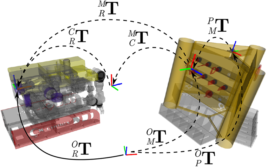
An illustration of the transformations between the vehicle and the panel. ROV: remotely operated vehicle.
Our approach focuses on the estimation of position and orientation of the panel with respect to the origin of the vehicle trajectory. Our approach incorporates a priori knowledge, especially the CAD model of the panel and the placement of the visual markers at known locations on the panel. Based on this, the panel pose in the odometry frame

Consequently,
Vehicle localization
Localization is a challenging task, especially in underwater conditions, due to noisy sensor readings typically based on acoustic devices like ultra-short baseline (USBL) systems, single-beam or multi-beam sonars, DVL, or readings provided by inertial navigation systems. Consequently, localization methods rely on multiple modalities to increase reliability. 24,25 A typical and well-established approach to deal with sensor fusion is the EKF, 26 which allows incorporating the different modalities on the basis of their different uncertainties.
In order to increase the pose accuracy, we exploit the panel as a visual landmark due to its static pose on the seafloor and its visual augmentation with multiple markers. Once the panel pose is estimated, the robot pose can be inferred and used as an additional EKF input modality. In the following, we describe our EKF-based localization system incorporating standard sensor readings and the visual landmarks.
Visual landmark-based localization
Figure 6 shows a sample pose estimate of a visual marker, which is used to infer the panel pose through the space transformations, shown in Figure 5,—note that the panel is only partially observed. The panel is taken as a fixed landmark and the robot pose


An example of a marker detection under sea trial conditions.
where

where
For calculating the mean

with


where
In order to use this robot pose estimate in the localization filter, a covariance matrix

Additionally, the element-wise orientation variances
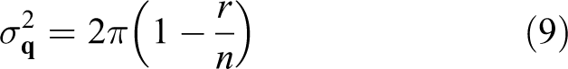
with

Finally, the covariance matrix

Eventually, a covariance matrix

The full robot pose estimate
Extended Kalman filter
As mentioned before, we use a standard EKF
26
to estimate the robot pose over time with a state space that consists of position
Experiments and results
Data collection at sea trials
The results presented here include extensive field trials of 2 weeks each time in the Mediterranean Sea off the shore of Marseille in June/July 2017 and in June/July 2018 (Figure 7). A test panel was developed for validation by the DexROV project partner “Compagnie maritime d’expertises (COMEX)”. COMEX also provided the Apache ROV and the Janus-II vessel for the sea trials. The panel served as target for the trials to emulate different scenarios, for example, offshore oil-&-gas facilities or the handling of archeological artifacts (Figures 6, 1 and 8). The panel consists of three sides, which are equipped with mock-up elements. One side is used to test components in offshore oil-&-gas interfaces based on the ISO 13628 standard including, for example, valves and wet-mate connectors. Furthermore, a biologic panel including mock-up corals and an archeological box including mock-up ceramics are included. The panel is augmented with ArUco AR markers as reference points to aid navigation.

Impressions of sea trials in Marseille.

The ROV and the test panel during the field trials. ROV: remotely operated vehicle.
The panel was submerged at different depths under different weather conditions with accordingly different visibility conditions. In order to provide a reliable estimate for the alignment, only marker pose estimates with respect to the ROV camera are used, that is, other cues are neglected due to high noise level of the other available sensor feeds (e.g. DVL, USBL, IMU). The experimental setup facilitates experiments ranging from pure algorithm performance experiments considering noise-free ground truth sensor feeds over increasing noise levels under real-world sea trial conditions. Especially, a high-fidelity simulator in the loop (SIL) based on Gazebo can be used to replace components for testing purposes. This is also of interest during the development of the system components and their integration. It allows, for example, the investigation of bottlenecks, constraints, and expected performance under certain environmental conditions or for specific configurations.
Panel pose estimation
The first benchmarking test

where
Figure 9 shows the mean

As expected, our approach features very high accuracy in the noise-free environment
Localization
The next test
Evaluation measures
In order to provide meaningful numerical results, we introduce the following error measures: Robot pose estimate error (simulated data):
The pose estimate error of Robot pose estimate error (real-world data):
To evaluate benchmarking tests on real-world data, we use the robot pose estimate given by the marker Relative image quality:
Furthermore, we use several measures for all images where the ground-truth landmark can be detected. This comprises of the NIQMC metric,
29
a model of visual image quality with respect to contrast distortion, as well as the number of correspondences between two consecutive images of several established feature descriptors, which are commonly used for registration, recognition, and mapping. All of the measures are normalized over all collected real-world data, that is, the resulting quality measures are relative numbers with the help of which different images can be qualitatively compared. From all measures, we compute the mean


where

and

is one individual image quality measure.
—localization in simulation
For real-world underwater localization, no accurate ground-truth data are usually available. For this reason, the performance of the proposed localization filter that integrates visual landmarks into the EKF is tested in high-fidelity simulation first.
In this test
During this movement, the ground-truth robot pose in simulation Integration stage:
During development, we initially execute
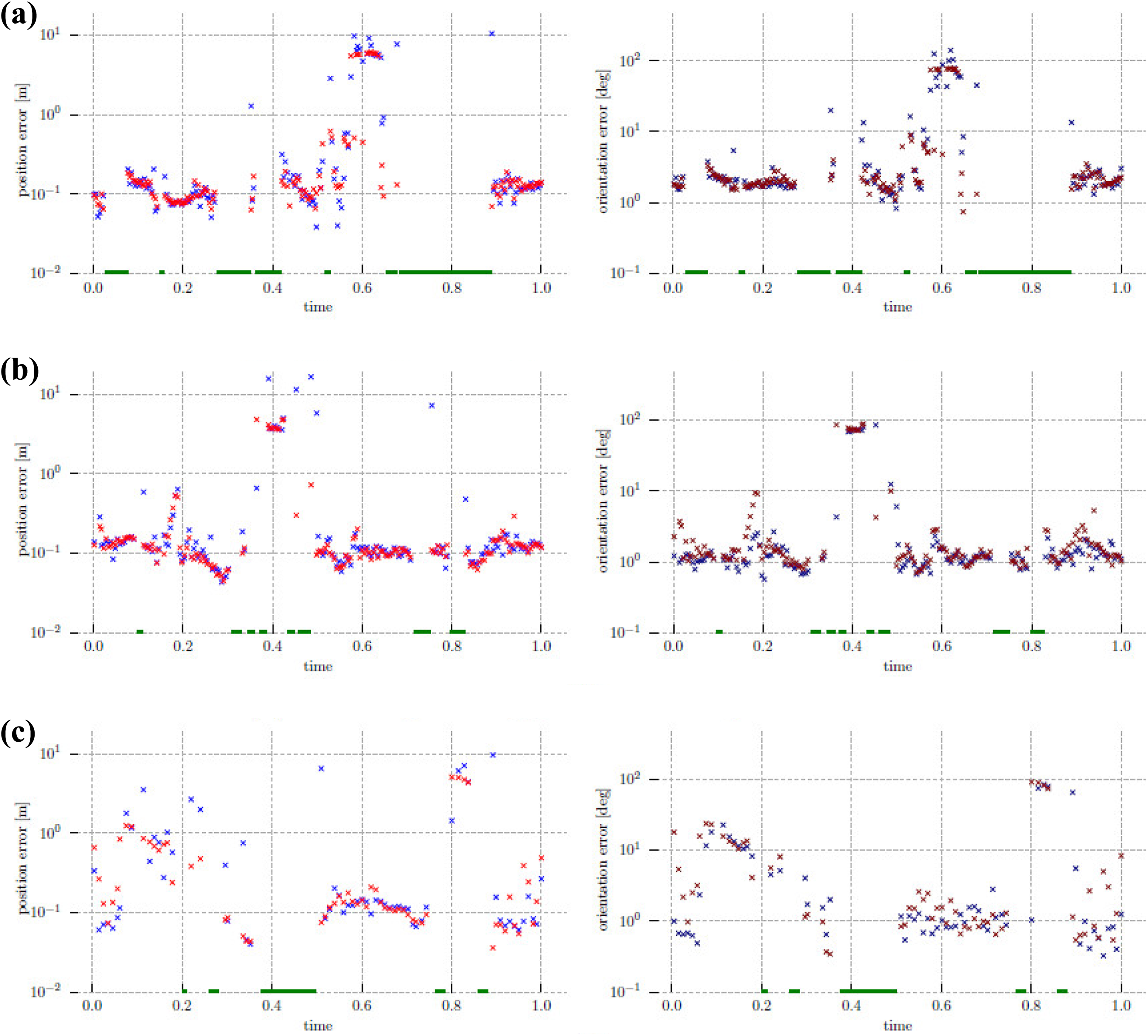
Figure 11(a) shows the driven-off trajectory with the resulting pose errors; this and the detailed error breakdown in Figure 10(a) show that whenever no marker is detected for a while, the EKF error increases significantly on the next reading, but then quickly reconverges toward ground truth. On parts of the trajectory where markers are constantly visible, the localization error decreases substantially below 0.3 m/3°, for example, between time marks

Further down the system integration path, Validation stage:
Within the validation stage, the method was tested again on the 2018 field trials data where a circular trajectory has been recorded (see Figure 11(c)). In contrary to the integration stage, a full round was performed around the panel with no markers recognized for a while (top-right part of the figure), but then the localization is quickly on track again as soon as the next marker is perceived. Together with the position and orientation errors shown in Figure 10(c), the localization on simulated sensor data is shown to be similar to the results from the integration stage. This means that the localization method itself works sufficiently well to be deployed with purely real-world data as in the next tests
—Real-world localization using only core navigation
In order to get a baseline to compare the performance of the localization filter when integrating visual landmarks, only core navigation, that is, a standard approach with an EKF on DVL and IMU measurements, is used in this subtest. This is also done for tuning the use of visual markers in the EKF, because navigation sensors are not integrated in the simulation at this development stage. The results of this subtest are depicted and described together with the following subtests in the next subsection.
—Real-world localization with visual markers
In these tests, we show the localization results using all sensor data recorded in field trials along with visual marker-based pose estimates. A description of the respective tests is given in Table 1. Figure 12 shows experimental results. Since no ground truth is available in this real-world underwater scenario and all errors are given with respect to the ROV pose as recognized from the visual markers, during parts of the trajectory where no markers have been perceived, no error measures can be computed.
Description of localization tests

EKF: extended Kalman filter.

As expected, the EKF instance with only core navigation sensors as an input (
This means that the vehicle localization does not get lost as often as with a lower
The trajectory recorded in the validation stage (see Figure 11(c)), in contrary to the one of the integration stage, leads around the whole testing panel, covering also the parts where less visual markers are placed. In addition, the visibility and hence marker detection percentage with respect to the trajectory length was lower on the days when this trial happened. This is easily visible in the relative image quality mean (
Tests

Conclusion
We presented an advanced navigation system for applications in the context of intervention missions, that is, underwater manipulation tasks, which require a high amount of precision and robustness in real time from the navigation system. For this purpose, a core navigation system in form of an EKF with input from a DVL and an inertial navigation system is extended by visual odometry using artificial markers. Concretely, AR markers on a target structure are used. The presented system has a high TRL, featuring an intelligent vision system suited for deep-sea operations on a commercial off-the-shelf ROV. The system was validated among others in two intensive field tests running off the shore of Marseille, France, where a substantially increased navigation performance due to the use of the vision system was demonstrated.
Footnotes
Acknowledgement
The presented research was carried out in the project “Effective Dexterous ROV Operations in Presence of Communications Latencies (DexROV)”.
Declaration of conflicting interests
The author(s) declared no potential conflicts of interest with respect to the research, authorship, and/or publication of this article.
Funding
The author(s) disclosed receipt of the following financial support for the research, authorship, and/or publication of this article: The project “Effective Dexterous ROV Operations in Presence of Communications Latencies (DexROV)” is supported by the European Commissions Horizon 2020 Framework Program for Research and Innovation, under the topic “Blue Growth: Unlocking the Potential of Seas and Oceans”, BG6-2014 “Delivering the subsea technologies for new services at sea”.