
Abstract
The objective of this article aims at the safety problems where robots and operators are highly coupled in a working space. A method to model an articulated robot manipulator by cylindrical geometries based on partial cloud points is proposed in this article. Firstly, images with point cloud data containing the posture of a robot with five resolution links are captured by a pair of RGB-D cameras. Secondly, the process of point cloud clustering and Gaussian noise filtering is applied to the images to separate the point cloud data of three links from the combined images. Thirdly, an ideal cylindrical model fits the processed point cloud data are segmented by the random sample consensus method such that three joint angles corresponding to three major links are computed. The original method for calculating the normal vector of point cloud data is the cylindrical model segmentation method, but the accuracy of posture measurement is low when the point cloud data is incomplete. To solve this problem, a principal axis compensation method is proposed, which is not affected by number of point cloud cluster data. The original method and the proposed method are used to estimate the three joint angular of the manipulator system in experiments. Experimental results show that the average error is reduced by 27.97%, and the sample standard deviation of the error is reduced by 54.21% compared with the original method for posture measurement. The proposed method is 0.971 piece/s slower than the original method in terms of the image processing velocity. But the proposed method is still feasible, and the purpose of posture measurement is achieved.
Keywords
Introduction
With the development of science and technology, the types and applications of robots are becoming more and more diversified which are competent for complex tasks. Although robot manipulators bring a lot of conveniences, most of the robots are not equipped with the function of online collision detection and detour. Robot arms barely sense hazardous conditions around and respond to, for example, when there are people or obstacles approaching. This may not only affect the use of robot arms but also cause safety problems when people work. 1 –3 Therefore, this article proposes a method of posture measurement by RGB-D cameras as sensory devices for articulated manipulators. The method combines the captured images from two opposite RGB-D cameras, filters, and segments the point cloud data (PCD) of each cylindrical link. A cylindrical model is used to estimate the shape of the individual link by computing the eigenvectors of each point cloud as normal vectors so as that the cylindrical parameters of cylindrical posture measurement can be obtained.
The posture measurement for the manipulator is a method to obtain the joint angle from the perspective of three-dimensional (3-D). The posture measurement for the manipulator is not only applied to obstacle avoidance for the manipulator in dynamic environment 4 but also necessary for visual servo control, 5 especially position-based visual servo 6 control. Some methods for posture measurement of manipulator in dynamic environments have been proposed, such as extended Kalman filter 7 and immune evolutionary algorithm. 8 Posture measurement is applied not only to the manipulator but also to the snake-like robots, 9 steerable catheter, 10 and even the driver’s head posture. 11
Vision-based posture measurement is the most commonly used method for manipulators, but the vision-based method usually relies on the robust image processing algorithm. Vision-based posture measurement for manipulators has attracted the attention of many scholars. Janabisharifi and Marey 7 introduced a method of position and attitude estimation of manipulator based on the Kalman filter method. This method can effectively filter out the noise in the image, but it cannot solve the dilemma of incomplete target caused by the occlusion of the manipulator joint. Suqi and Lim 12 proposed a posture measurement method based on the contour recognition method. First, the PCD is obtained by sensors, then the contour of the target is measured and the posture of the robot is estimated.
However, there are many noises in the PCD, so the noise filtering needs to be adopted in the preprocessing of the PCD. The segmentation and projection of geometric model is a new method for posture measurement. Narayanan 11 proposed a posture measurement for driver’s head based on geometric model. The posture of driver’s head is estimated by the segmentation and projection of geometric model, but the method based on geometric model depends on the complete target image. If the image of the target is incomplete, the precision of posture measurement will be lost. The cylindrical model segmentation method for manipulator is affected by the number of PCD. However, in practical applications, due to occlusion and other reasons, the PCD of the manipulator is often incomplete, so a method that will not be affected by the number of PCD is needed.
In the vision-based posture measurement method for manipulators, the use of PCD for posture measurement is a hot topic. In this article, a method of posture measurement for manipulators using PCD is studied, and a new method for posture measurement of manipulators is proposed, which is not affected by the number of PCD.
There are two contributions in this article. Firstly, aiming at the safety problems where robots and operators are highly coupled in a working space, this article proposes a posture measurement approach for an articulated manipulator. Secondly, the original method of normal vector calculation for PCD is the cylindrical model segmentation method. However, due to occlusion and other reasons, some joints of the manipulator cannot be captured by sensors, resulting in incomplete PCD. Therefore, the principal vector of PCD cannot be accurately calculated, and the parameter of the cylindrical model segmentation method is fixed, so the accuracy is not high. To overcome the shortcomings of the cylindrical model segmentation method, a principal axis compensation method is proposed in this article. This method cannot be affected by the number of point cloud cluster data. The experimental results show that this method improves the accuracy of posture measurement compared with the original method.
Plane model segmentation
13
is a common method to find the planar model by PCD
14
within random sample consensus.
15,16
This method uses iterations to find the fitting model from a set of original data.

The first step to achieve this purpose is to randomly choose three PCD points which are not collinear. Assuming that the three points are

Noise of PCD filtering
Spatial coordinate filtering
Images captured by a Kinect sensor do not require many zeroes and other points. Therefore, the first step is to filter the PCD which is redundant after loading an image to avoid noise interference as well as to reduce the point number of the PCD. 17 The second step is to register the manipulator workspace of the PCD with the spatial coordinates of the XYZ values and delete other PCDs.
Assuming that
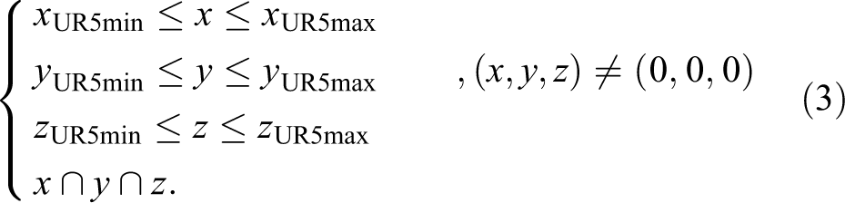
The principal axis of link 1 is parallel to the Y-axis of the world coordinate because the X-axis of the first RGB-D camera is parallel to the angle 0° of manipulator joint 1, and the Y-axis of the first RGB-D camera is parallel to the angle −90° of manipulator joint 2, and there is only the rotation rather than the translation within link 1. Consequently, it is allowed to let the principal axis vector of link 1 be

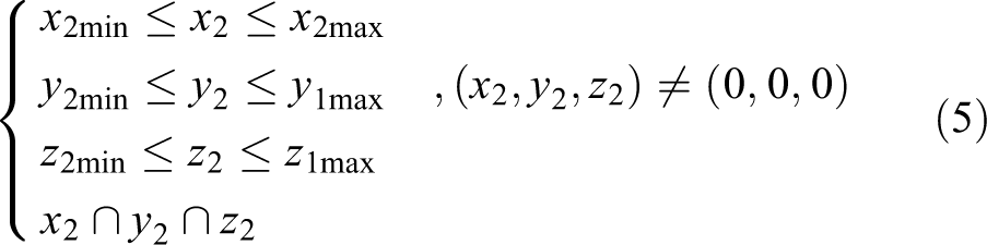
The filtered PCD is that of the manipulator without link 1. Next, and the PCD of links 2, 3, and 5 is divided into the color range of RGB value and separated from the original PCD. Although the translation of link 2 only moves on the plane which is parallel to XZ plane, the range of the working space can be divided through equation (5), where the PCD point of link 2 is
Nevertheless, other links are probably in the working space of link 2, while the posture of joint 2 is closing to the floor from the initial state; that is, the angular range of joint 2 is from −90° to −180° or from −90° to 0°. These situations may affect the segmentation results of cylindrical models with link 2. Therefore, the PCD of link 2 cannot be divided by spatial coordinate filtering.
Gaussian noise filtering
After separating from other links through equation (6),

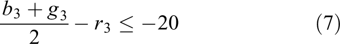
Similarly, the PCD of links 3 and 5 is able to be independent clusters, which are, respectively, defined clusters 3 and 5 in this article, after separating from other links through equations (7) and (8), where

Assuming that

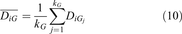
After that, the average distance
Similarly, the average value

Eventually, the PCD point


Link modeling from PCD
The successive step after the noise filtering of PCD images is to process the PCD images.
Normal vectors of point cloud surface
Before the segmentation of the cylinder model, the two points of PCD need to be chosen by their normal vectors. The normal vectors of PCD points are determined by their adjacent points because they are calculated from the covariance matrix of their adjacent PCD points.
18
Assuming that


The accuracy of the normal vectors

The density of the PCD computed by equation (20) is smaller than the actual value due to the incomplete cylinder of the PCD captured by RGB-D cameras; that is to say, the parameter value

Directions of link principal axis
The principal axis vector of the cylinders can be represented by the vector of sign symbol, which is one of the cylindrical parameters in the segmentation of cylinder model. This article describes how to get principal axis directions of the manipulator links. This section introduces the validation of principal axis direction of link 2 in the case of capture link 2. The center point

The center point


The principal axis vector of link 2: (a) principal axis of link 2; (b) projection diagram of center point; (c) the principal axis of links 1 and 2.
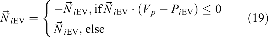
The principal axis direction of link 2 is the vector

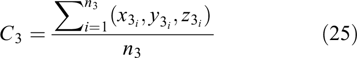
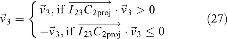
The method to verify the principal axis of link 3 is almost the same as link 2. The first step is to find the center point

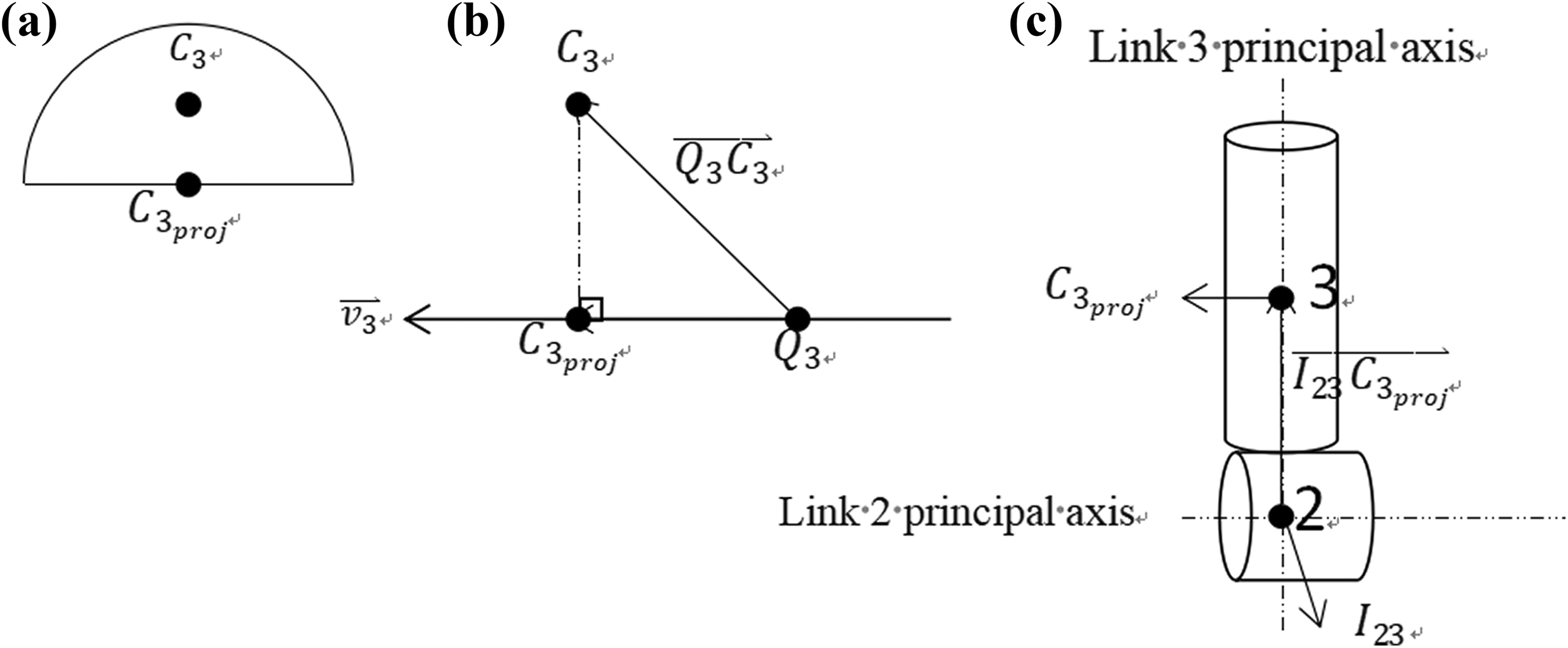
The principal axis vector of link 3: (a) principal axis of link 2; (b) projection diagram of center point; (3) the principal axis of links 2 and 3.
Similarly, the first step in terms of link 5 is to find the center point


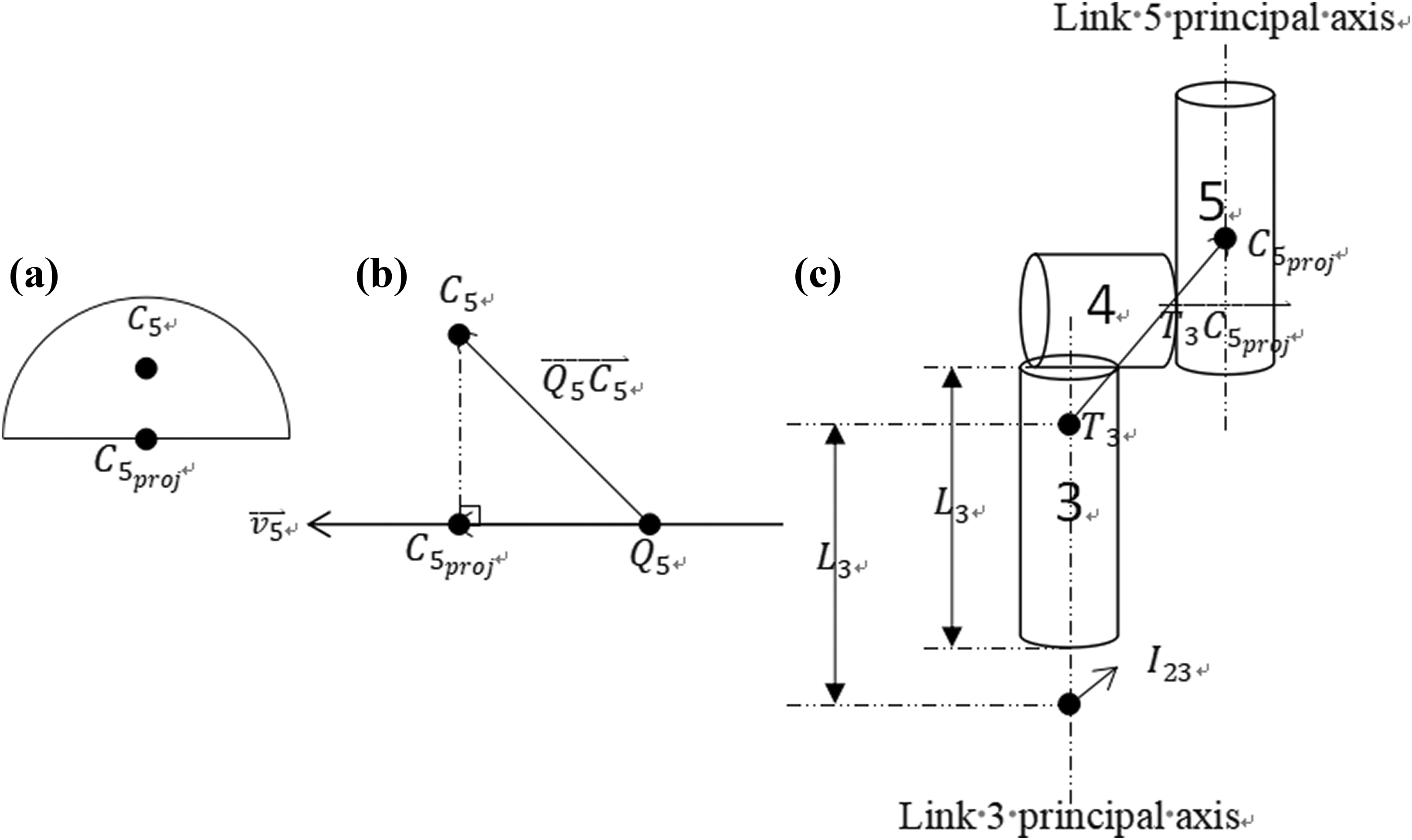
The principal axis vector of link 5: (a) principal axis of link 5; (b) projection diagram of center point; (3) The principal axis of links 3 and 5.
The next step which is different from the verifications of links 2 and 3 in this article is to find the end point


Principal axis compensating method
In terms of link 2, other links are probably in the working space of link 2, while the range of angular of joint 2 is from −90° to −180° or from −90° to 0°. Link 2 is probably blocked so that there is not any PCD of link 2 within cluster 2. Therefore, it is useless to find the principal axis of link 2 with cylinder model segmentation. The translation of link 2 only moves on the plane which is parallel to XZ plane, and the intersection O between links 1 and 2 is known. As a result, the equation of the link 2 translational plane is

The principal axis vector compensation of link 2.
For other links, if other links are blocked, as long as the cylindrical parameters of two adjacent links are known, the principal axis vectors of the links can also be found in the compensation method.
Angles of joint computing
In this article, the principal axis vectors obtained by clustering in cylindrical model segmentation are projected onto the rotational planes before computing the joint angles. According to the corresponding relationship between the joints and the links, the joint angles are computed from two projection vectors, as shown in Table 2.
In terms of the rotation plane, Figure 5 shows that the rotation plane of joint 1 is parallel to the XZ plane, and the rotation plane of joints 2 and 3 is the plane whose normal vector is the principal axis vector of joint 2 because of the same rotational directions, and because the rotational planes are vertical to the principal axis vector of link 2.

The explanation of joint rotational planes.
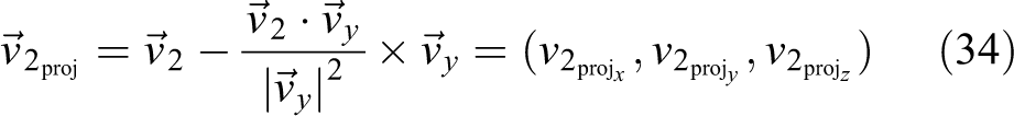
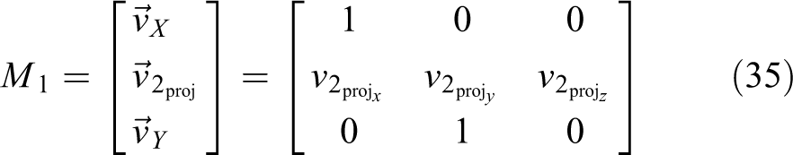
In terms of vector projections, a vector


For joint 1, the angle is between the X-axis of the first RGB-D camera and the principal axis vector of link 2. The threshold within cluster 2 which is set in this article is due to the influence whether other links block link 2 or not. The angle of joint 1 will be output directly if point number of cluster 2 is no less than the threshold; otherwise, the angle of joint 1 will be indicated that it is computed to let users know which manipulator postures that link 2 is blocked.
It is known that the rotational planar equation of joint 1 is
For joint 2, the angle is the principal axis vectors between links 1 and 3 according to Table 2 with 90°, and which is difference from the manipulator system; that is, the angle of joint 2 of the manipulator system is the angle of the principal axis vectors between links 1 and 3 which minuses 90°.
The explanation of experimental methods.

It is known that


Experiments
The experiments are the application experiment of using manipulator as the representative cylindrical robot arms to compute three joint angles and compare errors with the angles shown from the manipulator system.
Experimental configuration
In this article, manipulator is used as the research object, and the cylindrical robot arm is studied. The first step is to convert images to PCD through the RGB-D cameras, Kinect for Windows SDK 2.0, and PCL, and then the images captured by the second Xbox One Kinect are converted to the images whose reference point is the first RGB-D camera with rotational matrix and translational matrix. Then, the images are combined after the converting. The second step is to divide the PCD of the combined images and filter noise. Finally, according to the normal vector of PCD points and the order of cylinder model segmentation in PCL, some principal axis vectors are computed, and then three angles of manipulator joint are calculated through the vectors afterward. Then, the feasibility of this method is verified by comparing the errors between the computed angles and the joint angles displayed on the manipulator system.
The cylinders of PCD captured by two Xbox Kinect sensors are not complete. Because of the different radius, length, and posture of the cylinder, the number of PCD points is also changed. In addition, Zhang et al. 8 use fixed value to compute the normal vectors of the PCD points. The normal vector of the PCD point may be incorrect and the results are probably corrupted due to the selection of asymmetric points or fixed values that are not suitable for some cylinders. Therefore, this article proposes a method for calculating the normal vector according to the radius, length, and postures of the cylinders before the segmentation of the cylinder model.
Figure 6(a) shows the definition of manipulator in this article, where the numbers 1–8 are called links or cylinders of the manipulator. Robot arms can represent different positions through the rotation of joints. There are eight links (or cylinders) and six joints in manipulator. The X-axis, shown in Table 2, is the world coordinate axis, which is also the X-axis of the first RGB-D camera.

The definition of manipulator and the manipulator colored links. (a) The definitions of UR5 links. (b) The UR5 colored links.
The manipulator links are processed with different colors before capturing images. Links 1 and 4 and the arc below link 5 are kept gray. Links 2, 3, and 5 are processed with blue, red, and green, respectively. Links 6 to 8 and the blue caps of the links are processed with black. Figure 6(b) shows the colored links of the manipulator.
This paper finds the principal axis vectors of links 2, 3, and 5, and then computes the angles of joints 1 to 3 through vector computing.
In this paper, a posture measurement method is proposed. Firstly, two RGB-D cameras 20,21 and PCL are used to model the images, and the angles of joints 1 to 3 postures in manipulator 21 –23 are calculated. The next step is to verify the feasibility of this method by comparing the errors between the calculated angle and the joint angle displayed on the manipulator system.
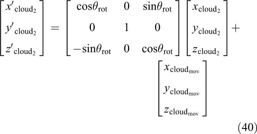
The reference point of the images captured by the second RGB-D camera is converted to that of the first RGB-D camera with rotational matrix and translational matrix, which are shown in equation (43)
After that the images are converted to the PCD and saved as the PCD files in order of the two RGB-D cameras, Kinect for Windows SDK 2.0, and PCL.
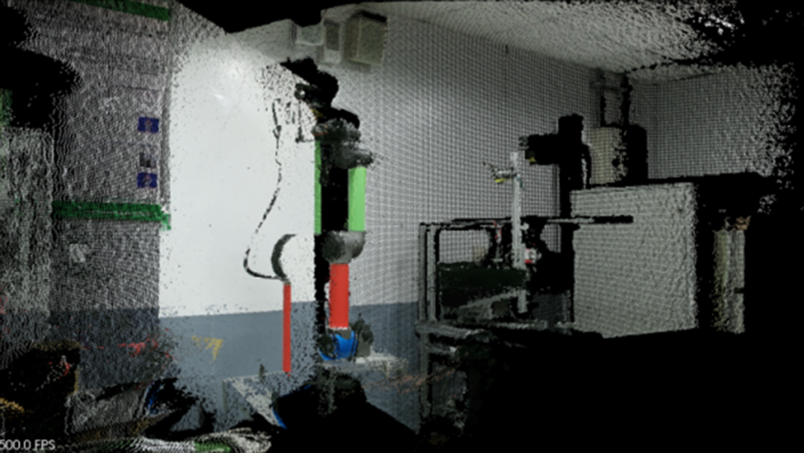
At last, the two PCD files are combined to a PCD file, and the combined image of the PCD is shown in Figure 7. The PCD image is divided into three different clusters according to colors and spatial information. Consequently, a Gaussian noise filtering process is performed for each cluster.
The definition of manipulator and the manipulator colored links. (a) The definitions of UR5 links. (b) The UR5 colored links.
In the environment of the application experiment, the base of the manipulator is about 0.7 m from the ground. The distance between the first RGB-D camera and the floor is about 1.333 m. The distance between the second RGB-D camera and the floor is about 1.273 m. The shortest distance between the first RGB-D camera and the manipulator is about 1.29 m. The shortest distance between the second RGB-D camera and the manipulator is about 1.4 m, and the distances on X- and Z-axes between the two RGB-D cameras are about 1.22 mand 1.24 m, respectively. The parameters of
The rotational angles of the manipulator joints are theoretically unlimited and the manipulator joints can rotate from 0° to 360°. Nevertheless, the manipulator joints are limited by the spatial environment and the manipulator black tubes. As a consequence, this article takes samples according to the symmetry of the rotational angles.
The samples are the manipulator postures where the manipulator only moves one joint by 1° once, and the moving trace is a semicircle. This article uses these samples to compute the rotational angles of joints 1 to 3. The samples of the manipulator postures are shown in Table 1, where
The samples of manipulator postures.

PCD: point cloud data.

The method steps of the application experiment.
The principal axis of link 2 needs to be computed within the method of principal axis compensating because the posture of link 2 is probably not captured by RGB-D cameras in some manipulator postures. This experiment uses the threshold of the PCD point number of cluster 2 to determine whether the method of principal axis compensating should be used or not. As the setting of the threshold, it is gotten by using the comparison of cylinder model segmentation and principal axis compensating with link 2 of the samples where the manipulator rotates joint 2.
Experimental results
The metrics of comparison is the errors between the computed angles of joint 1 and the angles of joint 1 displayed on the manipulator system. The fixed
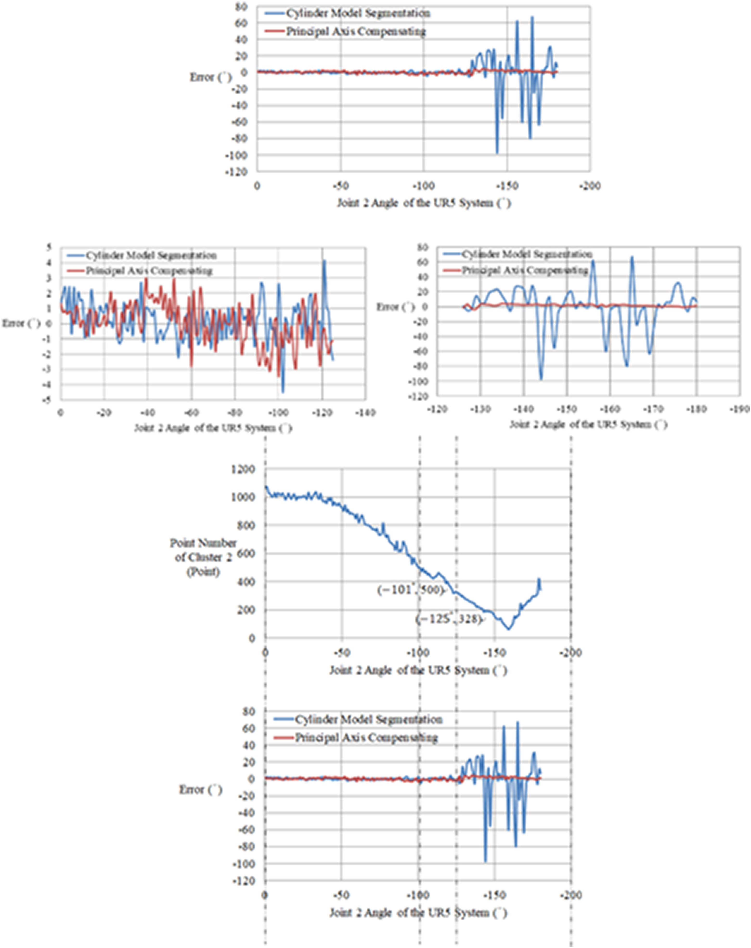
After experiments, the following results are obtained. The experimental results are shown in Figure 9. When the angle of joint 2 is −125°, which also means that the point number of cluster 2 is less than 328 points, the accuracy of the angles will be unstable within cylinder model segmentation, while principal axis compensating is not influenced by the point number of cluster 2. To increase the stability of the angular accuracy, the threshold is set to be 500 points.
The comparison of two methods.
In the application experiment, this article compares the proposed method with the original method, where the explanation is shown in Table 2. The original method, shown in Table 2, is according to the fixed value
Some of the experimental results of the samples are shown in Figures 10 to 12, where θ is the collective term of the control group

The experimental results while manipulator system. The three angles of UR5 system are 55°, −90°, and 0°.

The experimental results while manipulator system. The three angles of UR5 system are 0°, −79°, and 0°.

The experimental results while manipulator system. The three angles of UR5 system are 0°, −90°, and −48°.
Figure 10 shows the results within the original method and the proposed method with one of the samples chosen from rotational joint 1. The absolute errors of three joint angular of the proposed method are smaller than those of the original method according to the experimental results. Figure 11 shows the results within the original method and the proposed method with one of the samples chosen from rotational joint 2. The absolute errors of three joint angular of the proposed method are smaller than those of the original method according to the experimental results. Figure 12 shows the results within the original method and the proposed method with one of the samples chosen from rotational joint 3. The absolute errors of three joint angular of the proposed method are smaller than those of the original method according to the experimental results. All of the experimental results of the samples are shown in Figures 13 to 15 and Table 3. From the experimental results shown in Table 3, it can be seen that the proposed method reduces the error of posture measurement for the manipulator system from the two aspects of average error and standard deviation. But the average velocity of image processing is slower than that of the original method.

The errors of joint 1 angles.

The errors of joint 2 angles.

The errors of joint 2 angles.
The explanation of experimental methods.

The horizontal axis of Figure 13 is the angle of the rotational joints in Table 1, and the vertical axis is the angle of joint 1 where the manipulator system minuses the original method and the proposed method, respectively; that is to say,
In this article, a method for posture measurement of the manipulator by processing PCD of different joints is presented. Firstly, the image of the manipulator is captured by two Kinect sensors, and then the PCD is preprocessed by image merging and noise filtering. Finally, the principal axis of the joint is calculated by a principal axis compensation method, and the angle of the joint is estimated by the principal axis. In this article, a multi-joint manipulator is studied, and the point cloud clusters of different joints can be obtained by model segmentation for different types of robots, such as underwater vehicle-manipulator system. 25,26 If the perceptual noise of Kinect sensors in underwater environment can be overcome or the noise in PCD can be filtered better, this method can provide a new solution for the posture measurement of underwater vehicle-manipulator system.
The main factors affecting the precision of posture measurement are the influence of noise in PCD and the incompleteness of PCD. Our future research will focus on the following three aspects: Firstly, we will improve the noise filtering method in point cloud and design a robust noise filtering algorithm to increase the number of effective PCD. Therefore, the precision of posture measurement of manipulator will be improved. Secondly, the incompleteness of point cloud data will also affect the accuracy of posture measurement, and the incompleteness of point cloud data is often caused by external environmental factors such as occlusion or environmental noise. 27,28 An effective method of PCD completion will bring new solutions to this problem. Therefore, we will study the method of PCD completion and reduce the impact of environment on image acquisition. Thirdly, a robust point cloud clustering algorithm can partition different types of PCD, which can also improve the processing speed of PCD. The higher the partition accuracy of PCD, the higher the accuracy of posture measurement.
Conclusions
Aiming at the safety problems where robots and operators are highly coupled in a working space, a posture measurement approach for an articulated manipulator is proposed in this article. In order to overcome the dilemma that the accuracy of cylindrical model segmentation method is not high when the number of PCD is incomplete, a principal axis compensation method is proposed in this article. Although the proposed method in this article is slower than the original method in terms of the image processing velocity due to the more one step of Gaussian noise filtering, where the image processing velocity of the proposed method is about 5 piece/s, and the range of the proposed method is smaller than that of the original method in terms of the overall errors, where the error range of the proposed method is between about 5° and −5°. That is, the accuracy of the proposed method is better than that of the original method. The experimental results show that the proposed method is more accurate than the cylindrical model segmentation in posture measurement when the PCD is incomplete. At the same time, under normal circumstances, the result of using cylindrical robot arm posture measurement method proposed in this article is as good as that of using cylinder model segmentation with the original method according to the experimental results in this article.
Footnotes
Declaration of conflicting interests
The author(s) declared no potential conflicts of interest with respect to the research, authorship, and/or publication of this article.
Funding
The author(s) disclosed receipt of the following financial support for the research, authorship, and/or publication of this article: This work is supported in part by the Shaanxi Province Key Research and Development Program of China under Grant No. 2018GY-187, in part by the Aeronautical Science Foundation of China under Grant No. 2016ZC53022, and in part by the Seed Foundation of Innovation and Creation for Graduate Students in Northwestern Polytechnical University under Grant No. ZZ2018169.