
Abstract
This article presents a design and control framework for a prototype of lower extremity exoskeleton to enhance the human strength during locomotion. The hybrid control strategy is practically applied according to the two gait phases, that is, stance and swing. The weight shift method based on human’s weight shift information was proposed and implemented to acquire the detection of gait phase. In the stance phase, a stiff virtual wall method is applied to support the entire weight of the exoskeleton while carrying a heavy payload. Direct feedback and feed-forward torque control are used to reduce mechanical impedance in the swing phase. In experiments, to verify the performance of the proposed control strategy, a human subject wearing the prototype of power-augmenting lower extremity exoskeleton was able to walk with a 50-kg (110-lb) payload at a maximum speed of 1.67 m/s (6 km/h). Satisfactory results were obtained with regard to walking experiments with the heavy payload.
Keywords
Introduction
A lower extremity exoskeleton (LEE) attached to the outer surface of the lower body of a human has been extensively developed and studied to assist human’s locomotion abilities in various fields. 1,2 Depending on its purpose, an LEE can be roughly divided into either a power-assisting or a power-augmenting exoskeleton. A power-assisting LEE can provide the ability to support and/or assist humans. Such an exoskeleton for rehabilitation purposes was designed for therapy or to help injured patients or those with physical disabilities 3,4 and is a representative of power-assisting LEEs. Many such LEEs have been used to assist the rehabilitation process, such as Lokomat, 5 LOPES, 6 and ALEX. 7 Another area relating to power-assisting LEEs involves the assistive purposes of the activities of daily life for elderly and disabled people. In this context, the objective of the LEEs is to enhance the quality of life of a human by assisting them in activities of daily life such as walking, sitting down, and standing up. 8,9 These assistive exoskeletons have been applied to assist the elderly and/or people with physical disabilities. For those with physical disabilities, the LEEs can provide an ability to replace and/or assist the deficient function of the human motor, such as ReWalk. 10,11
On the contrary, the objective of a power-augmenting LEE is to accomplish missions that are difficult to achieve solely by human power. For example, it enables high load-carrying operation, which is considered as a representative example of the power-augmenting applications. Examples of LEEs for power-augmenting purposes include BLEEX, 12,13 EXOS, 14 and HULC. 15 The BLEEX was demonstrated for a walking experiment with a 34-kg payload at an average speed of 1.3 m/s (about 5 km/h) in the study by Kazerooni and Steger. 16 The main advantage of the locomotion control method used in the BLEEX is its minimal use of sensory information, since it does not require the measurement of the force of interaction between the user and the exoskeleton. The main limitation of this method is that a precise dynamic model may be required. Moreover, the identification of parameters for the modeling process of an exoskeleton requires considerable time and effort, where this process is subject to uncertainties in the case of the dynamics-based models. In Lim et al.’s study, 17 HEXAR-CR50 was demonstrated through experiments with a payload. It was operated with a 20-kg payload at a maximum speed of 0.8 m/s (3 km/h). Besides, an upper limb exoskeleton for human power amplification was designed and evaluated using a dynamic model-based approach. 18 Recently, the system design and locomotion control methods were proposed and evaluated for a hydraulic LEE to achieve a target mission (with 45 kg payload at 4 km/h walking speed) by our research group. 19
Furthermore, the demand of the power-augmenting LEE was mainly addressed in a military area. According to the US Naval Research Advisory Committee, 20 a load of the marine rifleman was approximately 73% (123 lb based on average weight of a soldier) of the body weight during a march. It was recommended to reduce the load to 45% (76 lb) of the body weight. Therefore, we have chosen a 100-lb (50-kg) payload to carry by a user. Furthermore, since a typical human can walk at approximately 4 to 6 km/h, the walking speed of a human wearing the LEE was set 0 to 6 km/h in this study. Although a variety of actuators, such as hydraulic, electric, and pneumatic, have been applied to LEEs, electric actuators were adopted in this study due to their fast response. Difficulties in controlling LEEs with the electric motor and gear systems arise due to impedance effects between the LEE and the human leg. Consequently, mechanical impedance (i.e. the effects of inertia, damping, friction, etc.) of the exoskeleton must be compensated for using appropriate methods. In particular, this issue related to the mechanical impedance emerges during the leg-swing motion because the swinging leg of the exoskeleton was required to track human motion. Regarding this issue, model-based control of the exoskeleton system can cause instabilities due to an improper estimation arising from the unknown nonlinearity or the uncertainties in previous studies. 21,22 Therefore, it is necessary to measure the signal that can estimate the force or torque between the user and the LEE to apply the model-based control technique.
In this article, the prototype of power-augmenting LEE, which is composed of 14 degrees of freedom (DoFs), is designed and developed to carry a heavy payload while walking quickly, particularly for military uses. A semi-anthropomorphic design was selected through the human gait analysis to provide a natural motion to a wearer. The LEE developed in this study was designed to satisfy the requirement, that is, a walking speed of 6 km/h while supporting a load of 50 kg. In fact, the LEE introduced in this study have a similar structure to the existing LEEs and have very few special features in terms of mechanism design. Note that it is challenging to find a LEE that supports a load of 50 kg and has a walking speed of 6 km/h except for HULC. Therefore, the focus of the overall mechanical design was to consider the particular requirement, that is, a walking speed of 6 km/h while supporting a load of 50 kg. Besides, the motor gear system with a torque sensor was developed to provide direct use of torque signal.
Examples of the direct use of force (torque) sensors in the LEE are presented in previous research studies. 23 –26 The torque sensors installed in joints are similar in their use, but the control methods used are different from those proposed in this study. The force (torque) sensors and force (torque) feedback control methods have been used to compensate for undesired interaction forces generated due to mechanical impedance. The use of these approaches was simple but effective for controlling mechanical impedance. However, the main disadvantage of these approaches is that a modification in the mechanical design can be required due to the installation of sensors to obtain force (torque) measurements. Moreover, most of these studies were only conducted to identify the muscular forces or improve transparency of the actuating system. The distinguished contributions in this article are practical locomotion control method and are as follows: The locomotion control method applied to the LEE utilizes a hybrid control, consisting of a stance controller and a swing controller, based on the detection of the gait phase (GP) of the wearer. An intuitive method using a weight shift of the wearer to detect the GP is proposed and evaluated. The stiff virtual wall method is used to control the leg-stance motion. The swing controller based on direct feedback and feed-forward torque control algorithm is designed and evaluated to apply to the prototype of LEE. To investigate the feasibility of the proposed control method, walking experiments on a treadmill were conducted and assessed through a user wearing the prototype of the LEE. Moreover, the muscular forces are also measured using electromyography (EMG) sensors to verify the effectiveness of the proposed stance and swing controllers.
Design and development of power-augmenting LEE system
A semi-anthropomorphic design was selected through the human gait analysis for the developed LEE. The experiment to analyze the human gait consisted of two steps. The first step was conducted with 12 infrared light markers attached to a human in an area surrounded by motion capture systems for various environments, such as longitudinal and lateral slopes, a vertical obstacle, and a stair. In this step, the range-of-motion (ROM) of the LEE was determined for these environments while carrying heavy payloads as shown in Table 1. In the second step, an unpowered mockup was used to estimate the power required to accomplish the load-carrying mission. The unpowered mockup used in this experiment consisted of absolute encoders, load cells, and attitude heading reference system to measure the joint angles, the ground reaction forces (GRFs), and the attitudes of the human–exoskeleton system. The design specification of the power-augmenting LEE was established through above two-step experiments.
Range of motion for the power-augmenting LEE.
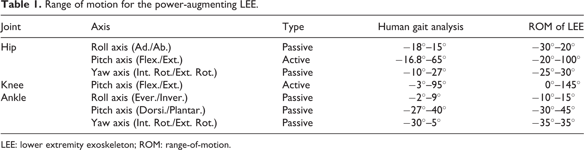
LEE: lower extremity exoskeleton; ROM: range-of-motion.
The primary objective of this study is the development of a power-augmenting LEE to be able to bear a heavy payload and walk at normal speeds. In this study, we considered that the normal walking speed was set from 0 to 6 km/h and the effective weight of the heavy payload was set to 50 kg based on the military report. 20 Consequently, the objective is that a healthy human wearing the LEE should be able to walk at 6 km/h maximum speed with a 50-kg payload. Regarding this, the design requirements related to the payload and walking speed are considered in determining the actuation modules (motor capacity, gear reduction ratio, and so on). The actuating module is mainly composed of a brushless direct current motor (RBE 02110, Kollmorgen) and a harmonic gear (CSG-25-100-2A-GR, RST). The torque of the actuator is that nominal, maximum, and peak torques correspond to 95, 172, and 255 Nm, respectively. The maximum speed of the actuator is 71 r/min at 72 V.
Figure 1 shows the prototype designs of the power-augmenting LEE developed in this study. The upper body of the LEE, which consists of spine, controller, and payload, is shown in Figure 2(a). Although the power-augmenting LEE has 14 DoFs, the hip and knee joints in sagittal plane were determined as active joints through the human gait analysis. Therefore, four joints (i.e. left/right hip and knee pitch joints) are actuated using the developed actuators. The remaining 10 joints (i.e. left/right hip roll and yaw joints, ankle roll, pitch, and yaw joints as shown in Figure 1(b) and (c)) were selected as passive joints. Note that these joints are not actuated but essentially used for locomotion. The passive joints were experimentally chosen and composed of torsional springs with different stiffnesses as shown in Figure 1(b) and (c). Besides, hip yaw joint axis can be adjusted by a sliding mechanism, that is, circular, linear motion (LM) guide. The thigh and shank links are shown in Figure 1(d). The details of the ROM for all joints are listed in Table 1.

Mechanical design of components. (a) Spine, main controller, and payload; (b) hip joint module; (c) ankle/foot module; (d) thigh and shank links.
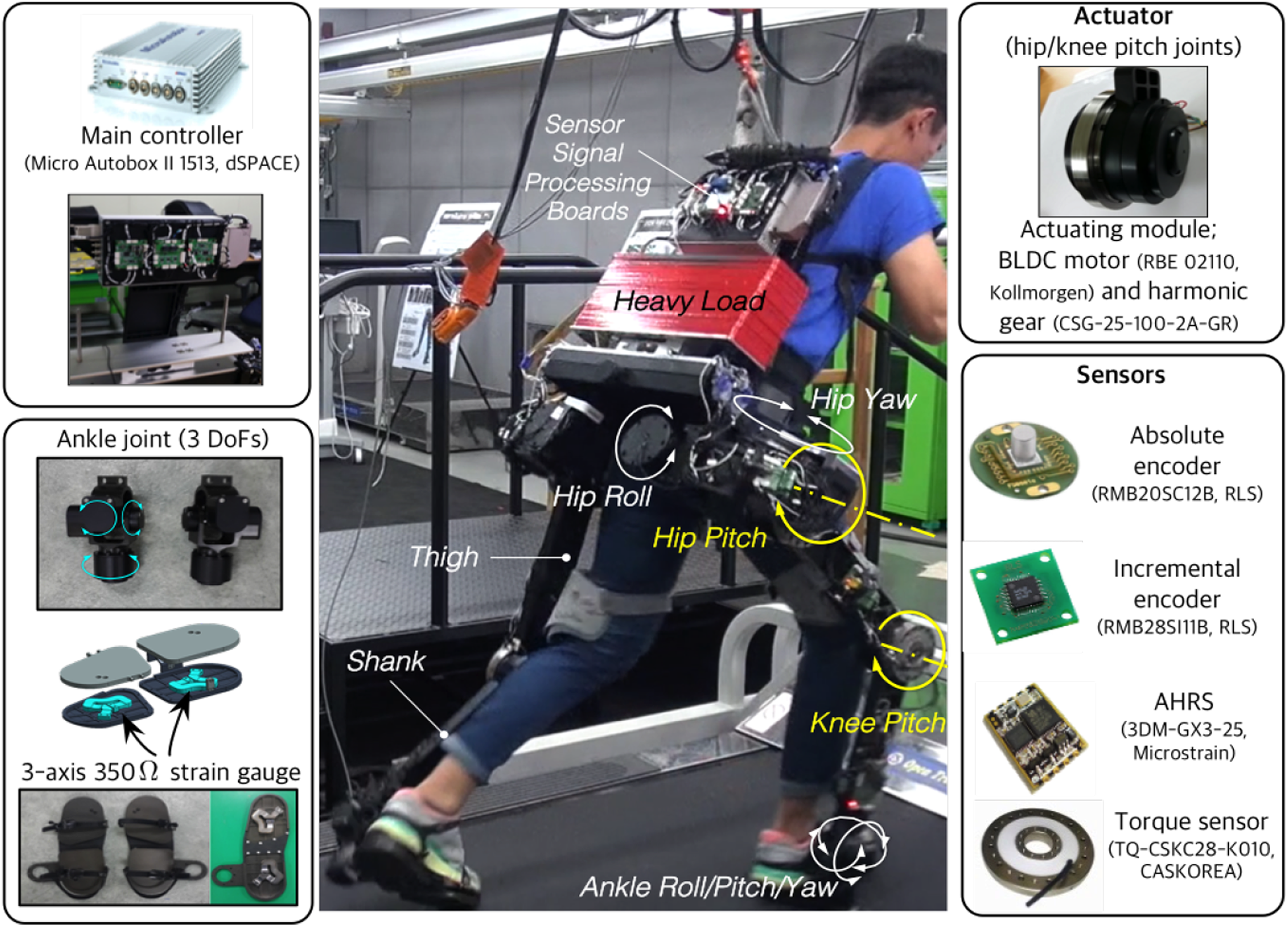
System configuration of the LEE including sensors and actuators. LEE: lower extremity exoskeleton.
The prototype of the power-augmenting LEE using hip and knee flexion/extension activities was built as shown in Figure 2. The total weight of the prototype of LEE is approximately 39 kg. Figure 2 shows the system configuration including sensors and actuators. The sensors used in this study were as follows: absolute (RMB20, RLS, Komenda, Slovenia) and incremental (RMB28, RLS) encoders were used to measure joint angles for all active and passive joints. The GRF was obtained from the foot sensor composed of strain gauges (3-axis, 350 Ω). The torques arising from the active joints could be measured using torque sensors (TQ-CSKC28-K010, CASKOREA, Gyeonggi-do, Republic of Korea) attached at the output shafts of the harmonic gear. These sensor signals were delivered using a control area network through the developed sensor signal processing boards. The controller used in this study was a commercial product (Micro-Autobox II 1513, dSPACE, dSPACE Inc.). The control algorithm was updated at 1 kHz (control sampling time was 1 ms).
Hybrid control strategy
Figure 3 shows the overall control structure of the human–exoskeleton system. H represents the muscular-skeletal part of the human body including the mass of the LEE, and yd is the desired joint motion. In general, a human can generate torques (τH in Figure 3) to follow the desired joint motion using the brain and muscles, if the human is healthy. This feature could not change even though the human wears the LEE. Therefore, we assume that a certain degree of stability can be charged in a healthy human, unlike a robotic exoskeleton system for rehabilitation purposes. To apply a hybrid control strategy, the GP in Figure 3 must be divided into two phases, that is, the stance and swing phases (ST and SW in Figure 3). Following this, the swing and stance controllers generate the appropriate control inputs (τA in Figure 3) according to the detected GPs, respectively.

Block diagram of the overall control structure for the human and LEE system. LEE: lower extremity exoskeleton; GP: gait phase; SW: swing phase; ST: stance phase.
GP detection
Walking motion can be represented by a periodic pattern called the GP. Figure 4 illustrates the sequential GPs and the definition of the hip and knee pitch joint angles used in this study. The fundamental division of the gait cycle is into stance and swing motions. In this study, we focused on the robust detection of the ST and SW while carrying a payload at normal walking speed. Since the dynamic characteristics of the LEE according to the GP are different, a classification method for the GP is required. 27 To classify the GP, the detection methods using various sensors (e.g. pressure sensor, load cell, strain-gauge, and so on) are common. 28 These methods based on physical sensors have a limitation concerning their implementation to actual exoskeleton control. The delay of the sensor signal affects walking performance. In other words, although the delay of the sensor signal may not be a problem when the walking speed is low, it results in instability of walking performance at high walking speed. For example, if a transition delay occurs due to the delay of the sensor signal when the leg is in the transition from the ST to the SW, the heel-off motion of the leg cannot be realized at an appropriate time. Also, it is possible to lose dynamic stability because of its delay.
The stance and swing motion phases can be considered to be easily detectable by examining the contact of each foot with the ground. However, even if the contact information of the foot is available, it is not easy to distinguish the transition between the stance and swing motions. It means that although the foot contacts with the ground when most of the weight is transferred to the counterpart foot, the GP of the contacting foot should be regarded as the pre-swing motion. There exist two transitions between the stance and SWs. The first transition occurs between the terminal stance motion and the pre-swing motion, which is likely to be capable of taking off the foot. The second transition between the terminal swing motion and the heel strike motion, which recognizes the contact with the ground, can be observed. We believe that the robust detection of the transition between the ST and SWs plays an important role in controlling the LEE.

Sequential gait phases and the definition of active joint angles, that is, hip (qh) and knee (qk) pitch joint angles.
In actual, the human gait is quite complicated, and its dynamics are different from one person to another even in the same stance motion phase. Biologically, the weight shift of the human can be observed from the human walking. In this study, we propose a weight shift method (GP in Figure 3) based on the weight shift change of the human. The weight shift is defined as the ratio of total weight to individual leg weight and is used to classify the GP

where
Figure 5 shows the experimental results to verify the performance of the proposed weight shift method. From the walking experiment, the weights and weight shifts of both legs can be obtained as shown in Figure 5(a) and (b). To verify the effectiveness of the proposed weight shift method, it is compared with the traditional weight threshold method. The traditional weight threshold method utilized the weight threshold of the contact leg. In this case, the weight threshold was set to 15 kg at each leg. The traditional weight threshold method was sensitive to the threshold value of the weight. In actual, although the experiments to decide the proper threshold value for the weight threshold method were conducted, the traditional threshold method was highly dependent on the human’s leg weight itself. For that reason, the proper threshold value at which the GP was well detected differed from one person to another. As a result, the threshold value (15 kg) that suitably detected the GP of the wearer participating in this experiment was selected by trial and error. However, since the proposed weight shift method depends only on the weight shift, it is less sensitive to weight value. In our case, when the 85% of the total weight is transferred to the contact leg, it recognizes as the ST. Otherwise, the phase can be considered as a SW. A comparison between the weight threshold method and the proposed weight shift method is shown in Figure 5(c). Although both methods similarly detect the GP, the proposed weight shift method can more quickly recognize the transition of the leg from the terminal ST to the pre-SW than the weight threshold method, as shown in Figure 5(d). In detail, the SW of the left leg was observed at 8.61 s from the weight threshold method. When the weight shift method was used, the SW was recognized at 8.58 s, which was approximately 30 ms faster than using the weight threshold method. Therefore, an user can stably move through the rapid transition from the stance motion to the swing motion. However, the detection of the transition from the swing to stance motion phases was relatively slower than the weight threshold method. The delay detection of the stance motion phase may not be significantly affected to the healthy wearer through various experiments. To be able to walk with a heavy payload at normal walking speed, the fast detection of the pre-SW plays an important role to maintain dynamic stability.
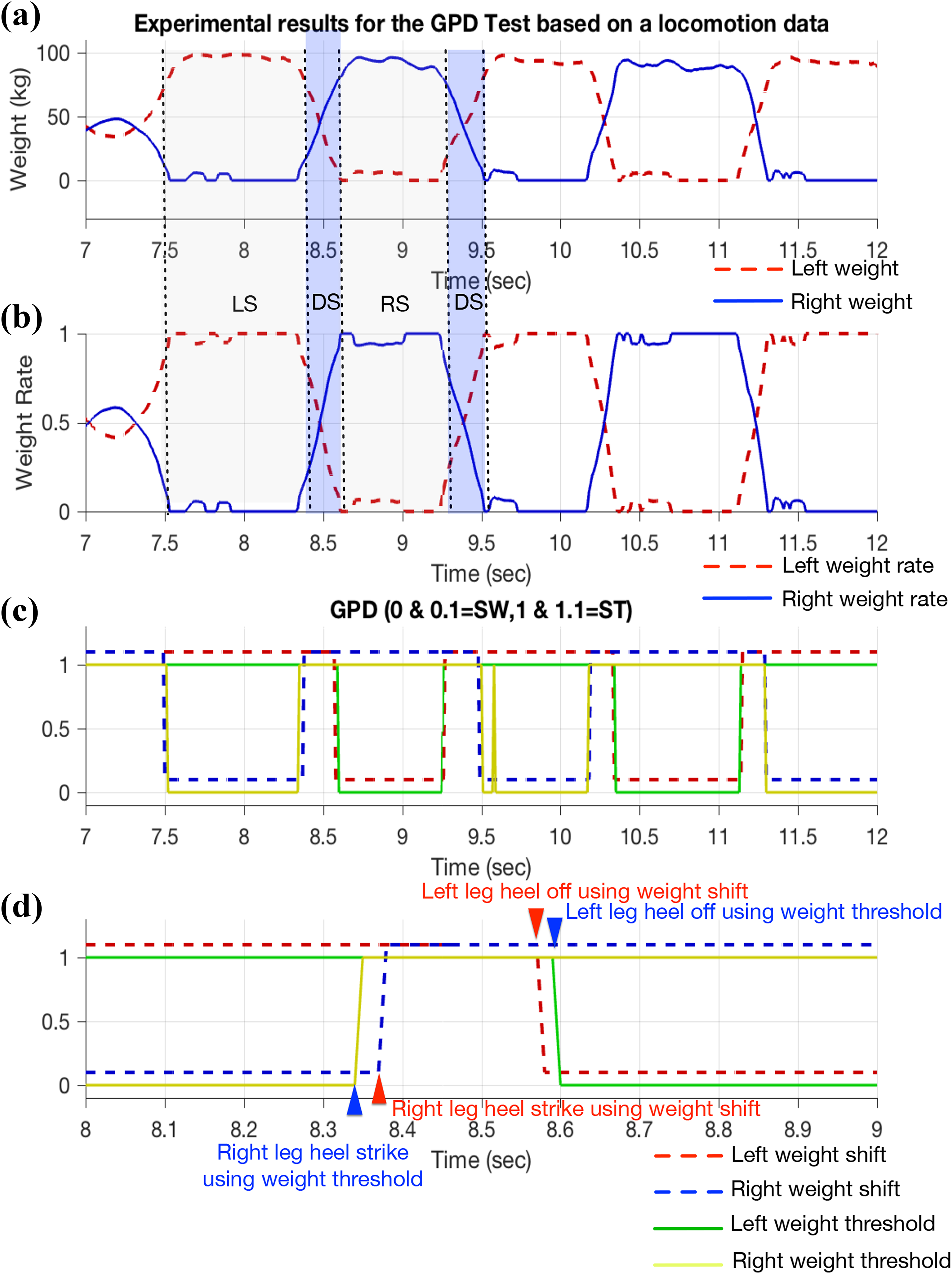
Experimental results to verify the proposed GPD method (LS: left leg stance and right leg swing; RS: right leg stance & left leg swing; DS: double leg stance): (a) measured weights for left and right legs, (b) weight shifts for left and right legs, (c) phase recognitions using weight shift method and weight threshold method, and (d) an enlarged figure of (c) to compare the two methods. GPD: gait phase detection.
Control of stance leg using stiff virtual wall method
Figure 6 shows the concept of the stance control method for the power-augmenting LEE. The control objective in the stance motion phase is to generate a torque or force that supports the weight of the human–exoskeleton system including a heavy payload. As a result, an augmented force can be required to achieve the load-carrying task, which is difficult to handle with only human force, for the developed LEE. The stiff virtual wall method
29
can be utilized in the stance motion phase. The predetermined positions (

where

Schematic of the stance control by using the stiff virtual wall method.
As shown in Figure 7, the experiment to verify the performance of the proposed stance controller was carried out with a 50 kg payload. The stance experiment was performed with only the left leg. Therefore, the total weight of the system including the payload was enforced to only the left leg. Without the support of the LEE, the user could not maintain a single stance posture. Furthermore, the EMG signals were measured to compare the human muscular forces while wearing the LEE and not wearing it. The muscular forces were measured at two points, that is, the gastrocnemius and the biceps femoris muscles considered as dominant muscles in the stance motion. The augmented torque was generated by the proposed stance controller to support the payload even in the single ST, as shown in Figure 7.

Experimental snapshots to verify the performance of the stance controller. The single stance posture by using the proposed stance controller can be maintained for the user with a 50 kg payload.
The experimental results using the proposed stance controller are shown in Figure 8. As mentioned earlier, the user attempted to maintain a constant posture of the left leg single stance (Figure 8(a)) in this experiment. Therefore, there were little variations in the joint angles and most of the total weight was forced on the left leg as shown in Figure 8(e) and (f). The assistive torques generated by the proposed stance controller are shown in Figure 8(b). The results show that the torque required for the knee joint was greater than that for the hip joint. In the stance motion phase, it was well-known that the variation in the joint angle was small and the required torque was large. In this experiment, the interaction torques (Figure 8(c)) can be roughly estimated from the difference between the measured torques obtained from the torque sensors (Figure 8(d)) and the assistive torques generated by the controller. The estimated interaction torques applied to the user were relatively small (i.e. within 15 Nm). These results showed that the assistive torques generated by the proposed stance controller played an important role to support the heavy payload in the single stance motion phase.

Experimental results to validate the performance of the proposed stance controller. (a) Gait phase, (b) assistive torques generated by the controller, (c) estimated interaction torques, (d) measured torques, (e) measured angles, (f) measured weights.
Figure 9 shows the results of EMG measurements for the above single stance experiment. As shown in Figure 9(a), the user maintained constant posture with the 50-kg payload during the single stance of the left leg, and EMG sensors were attached to the user’s gastrocnemius and biceps femoris muscles to investigate muscular forces. The maximum voluntary isometric contraction was introduced and applied to express the EMG measurement as the quantitative muscle strength and to compare the effectiveness of controller performance. 17,30 Therefore, we conducted experiments while the LEE was worn and not worn with the heavy payload. When the proposed stance controller provided assistive torque in the single stance test, the gastrocnemius and biceps femoris muscle forces were measured, as shown in Figure 9(b′). Besides, Figure 9(b″) shows the maximum force generated by the user with maximal effort. The measured EMG signals were filtered by a moving average filter where the width of the window was 0.01 s. Furthermore, the postprocessed signals (red lines in Figure 9(b′ and b″)), which were filtered by a zero-phase low-pass filter with a cutoff frequency of 10 Hz, were presented for better comparison. In addition, Figure 9(c) shows the statistical comparison of Figure 9(b′) and (b″) so that the difference can be quantified. The results show that magnitude of the EMG signals decreased. It means that the human was effectively supported by the power-augmenting LEE.

Comparison of EMG signals in the single stance test. (a) Rear view of the experiment, (b) measured EMG signals at gastrocnemius and biceps femoris muscles while wearing exoskeleton (b′) and not wearing it (b″), and (c) quantitative comparison. EMG: electromyography.
Direct feedback and feed-forward torque control for swing leg
In this section, we propose a swing control method based on direct feedback and feed-forward torque control for a human wearing the LEE. As mentioned earlier, the torque sensor was located between the output shaft of the harmonic gear and the corresponding link. Since the LEE was tightly coupled with the wearer, the torque sensor used in this study simultaneously measured the interaction torque between the human and the exoskeleton as well as that generated by the exoskeleton system. Figure 10 illustrates the block diagram of the human–exoskeleton control system in the swing motion phase. In the human part of Figure 10, if the human motion system can be viewed as a feedback control system, the desired motion (yd) can be tracked by taking the torques (τH) generated in the brain and muscles considered as sensors and actuators. Note that since the prototype of the LEE developed in this article was intended for healthy humans, it was assumed that the torque generated by the human could partially control the stability of the human–exoskeleton system. The swing motion phase can be considered the section from the pre-swing motion to the terminal swing motion of the human leg. The most important factor needed to rotate the leg in the swing motion phase is the compensation for the mechanical impedance of the LEE. Therefore, the proper compensation of the mechanical impedance must be achieved using a swing motion control technique.

Block diagram for the swing control of the LEE using the direct feedback and feed-forward torque control. LEE: lower extremity exoskeleton.
The muscular skeletal parts of the human–exoskeleton and the torque sensors used in this study are denoted as H and S in Figure 10, respectively. The estimate of inverse dynamics for H is denoted by

As mentioned earlier, the measured torque (τS) can be obtained from the torque sensor measurement
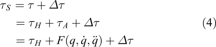
where

where τR represents the torque obtained from the inverse dynamics of the exoskeleton. It can be rewritten by

where

where
Figure 11 illustrates experimental snapshots for the performance verification of the proposed swing controller. In this swing motion experiment, only the left knee joint was actuated based on the proposed swing controller, whereas the left hip joint remained at 0° by the position controller. Figure 12 shows the experimental results for the performance of the proposed swing controller. The left knee angles (see in Figure 12(a)) varied from −15° to 85°. Figure 12(b) also shows the measured torque (τS) obtained from the torque sensor. Note that the measured torque (τS) was filtered by the low-pass filter (cutoff frequency = 10 Hz) due to its high-frequency oscillations. The torque (τR) calculated from the inverse dynamics is shown in Figure 12(c). The assistive torque (τA) generated by the proposed swing controller is shown in Figure 12(d). Note that the assistive torque was obtained based on the current input generated from the controller. The torque (τR) calculated from the inverse dynamics is shown in Figure 12(c). The assistive torque (τA) generated by the proposed swing controller is shown in Figure 12(d). The interaction torque (see in Figure 12(e)) between the user and the exoskeleton could be estimated and was relatively small (approximately +10 to −15 Nm). Note that the assistive torque shows high-frequency oscillations with relatively high amplitude in the section with oscillations of the estimated interaction torque since it was designed to minimize the estimated interaction torque. The high-frequency oscillations seem to dissipate while controlling the voltage for the desired current in the motor driver (ELMO used in this study). From the viewpoint of wearability, the user could not feel the high-frequency oscillations with the relatively large amplitude.

Experimental snapshots to verify the performance in the implementation of the proposed swing controller. This experiment was conducted for only the left knee joint.

Experimental results to validate the performance of the proposed swing controller. (a) The measured pitch angle of the left knee joint, (b) the measured torque obtained from the torque sensor, (c) the torque calculated from the dynamics, (d) the assistive torque provided by the proposed swing controller, and (e) the estimated interaction torque.
Furthermore, the EMG signals were measured to evaluate the muscular forces through the same procedure used in the previous section. EMG sensors were located at the gastrocnemius medial head and the lateral head considered as the dominant muscles to generate forces during knee flexion and extension activities to investigate the muscular forces. When the assistive torque was provided by the proposed swing controller during the single swing test of the left knee joint, muscle forces were measured as shown in Figure 13(a). Moreover, Figure 13(b) shows the maximum force generated by the user with maximal effort. Similar to the performance experiment of the stance controller in the previous section, the red lines in Figure 13(a) and (b) represent the postprocessed signals. Also, the statistical comparison is shown in Figure 13(c). The result shows that the magnitude of the EMG signals was effectively reduced. Therefore, the LEE was operated simultaneously with human motion.

Comparison of EMG signals in the single swing test. EMG signals were measured at the gastrocnemius medial head and the lateral head muscles while wearing (a) and not wearing (b) the prototype of the lower extremity exoskeleton, and its quantitative comparison (c). EMG: electromyography.
Performance evaluations through human walking experiments
This section presents experimental results to verify the performance of the proposed hybrid controller for the power-augmenting LEE. The walking experiments on the treadmill were conducted on human subjects wearing the LEE including a heavy payload to evaluate the performance of the proposed hybrid controller. Figure 14 shows the experimental snapshots for the walking test on the treadmill. The human subject in the snapshot was a 34-year old healthy male with weight of 72 kg. The treadmill speed was set from 0.0 to 6.0 km/h (1.6 m/s) to include a normal walking speed. Although the walking experiments were conducted by 3–5 humans, the representative result among the experimental results is presented in this section.

Experimental snapshots for walking on a treadmill with the heavy payload (50 kg) at a speed of 6 km/h.
Figure 15 shows the measured joint angles for actuated and passive joints. For actuated joints, hip pitch angles vary from 20° to 100° and knee pitch angles are between −30° and −80°. While actuated joint angles seem to be unaffected by the walking speed, the variations of the ankle joints are significantly increased as the walking speed is increased. With this regard, although the passive springs of the ankle joint have been determined to obtain the comfortable ankle motion, we figured out that the new ankle mechanism to obtain the variable stiffness could be required at high walking speed. The stance and swing controllers used in the walking experiment were implemented according to the detected GP, respectively. To analyze the performance of the proposed controllers, it was necessary to separate the stance and swing motion phases. Figures 16 and 17 show the estimated interaction torques in the stance and swing motion phases, respectively. For both results, there were high peaks at the starting point of each GP. These peaks were caused by discontinuities between the motion phases. As shown in Figure 14, the results showed the estimated interaction torques of 20–50 Nm and −30–10 Nm in the stance motion phase at low locomotion speed for hip and knee joints, respectively (i.e. approximately 0 to 4 km/h). The large interaction torques at 5–6 km/h walking speed (the green shaded area in Figure 16) were approximately observed from 10 to 80 Nm and from −30 to 80 Nm for hip and knee joints. In the swing motion phase at low walking speed, the estimated interaction torques of −20–40 Nm and −20–20 Nm for the hip and knee joints were observed as shown in Figure 17. Besides, the estimated interaction torques of −50–50 Nm and −20–30 Nm were observed at 5–6 km/h walking speed, as shown in the green shaded area of Figure 17. In practical, there are few kinds of literature to indicate the interaction torques because it is difficult to obtain the accurate value. However, Ka et al. 21 proposed and used the global fast sliding mode control to minimize the interaction force. Of course, even though the control methods used are different, the interaction torques were −15 to 30 Nm and −30 to 20 Nm at the hip and knee joint, respectively. Compared to these interaction torques, the estimated interaction torques in this study were considered to be similar.

Time history of all joint angles including actuated and passive joints.
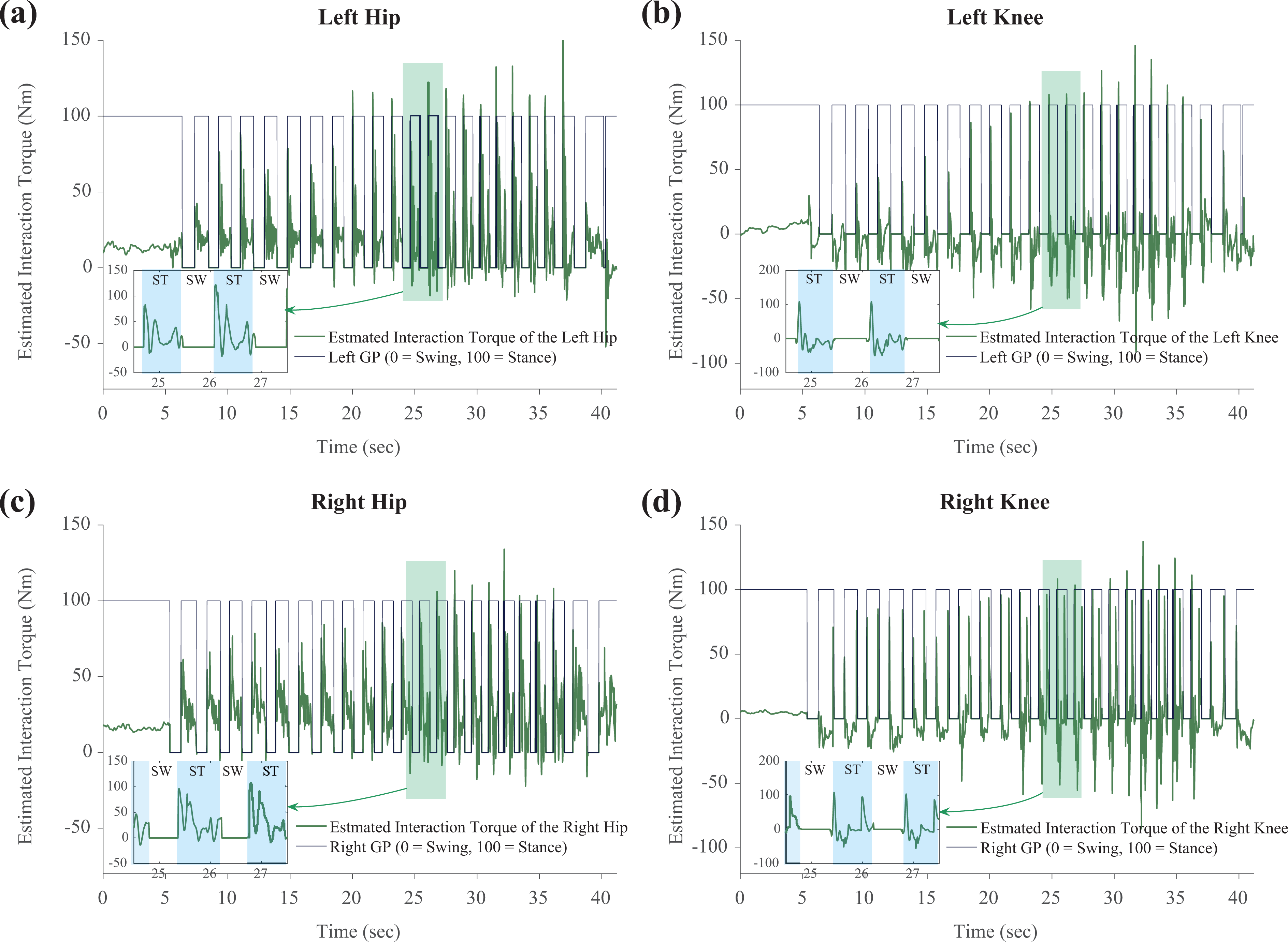
Experimental results of the estimated interaction torques in the stance motion phase. (a) Left hip joint, (b) left knee joint, (c) right hip joint, and (d) right knee joint.
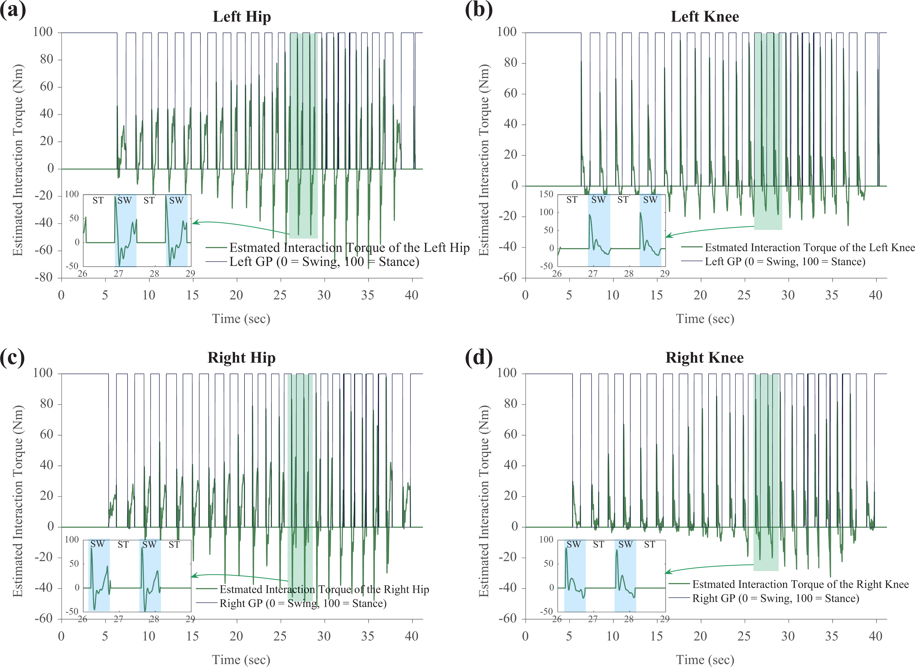
Experimental results of the estimated interaction torques in the swing motion phase. (a) Left hip joint, (b) left knee joint, (c) right hip joint, and (d) right knee joint.
From a practical point of view, the proposed controller was expected to be useful in the LEE in enhancing power. Furthermore, the performance of the controller was evaluated based on experimental walking tests carrying a 50 kg load. According to the experimental results, the user wearing the LEE can carry the heavy payload at normal walking speed using the proposed control method. Among military LEEs similar to those developed in this study, the HULC may be examined to compare the performance. HULC is known to have a maximum walking speed of 11 km/h for long durations and a maximum support load of 90 kg. Although HULC claims outstanding performance, direct comparison with the LEE in this study is difficult because it uses hydraulic actuators. As stated in “Introduction,” there are not many military LEEs operating at a walking speed of 6 km/h while supporting the load of 50 kg shown in this study.
Conclusions
The purpose of the study was to investigate a practical locomotion strategy for a human wearing the LEE including a heavy payload at normal walking speed. The prototype of LEE was developed to investigate the practical feasibility as a load carrier. The weight shift method based on the weight shift of the human subject was proposed and applied to detect the GP. The stance and swing controllers were independently designed and evaluated through experiments with a heavy payload. To support the weight of the whole system, the stiff virtual wall method was used for the stance leg. For the swing leg, the direct feedback and feed-forward torque control were utilized and evaluated in this study. These controllers yielded satisfactory results with regard to walking with the heavy payload (50 kg) at normal walking speed. The results of walking experiment on a treadmill showed that the overall control method was effective and operated well for the load-carrying mission at normal walking speed.
Footnotes
Declaration of conflicting interests
The author(s) declared no potential conflicts of interest with respect to the research, authorship, and/or publication of this article.
Funding
The author(s) received no financial support for the research, authorship, and/or publication of this article.
Supplemental material
Supplemental material for this article is available online.
References
Supplementary Material
Please find the following supplemental material available below.
For Open Access articles published under a Creative Commons License, all supplemental material carries the same license as the article it is associated with.
For non-Open Access articles published, all supplemental material carries a non-exclusive license, and permission requests for re-use of supplemental material or any part of supplemental material shall be sent directly to the copyright owner as specified in the copyright notice associated with the article.