
Abstract
This article proposes a new spatial 2-(PUU)2R hybrid mechanism that can perform the three degrees of freedom translation and one degree of freedom rotation and presents an analysis of the dynamics of the mechanism. An adaptive fuzzy terminal sliding mode controller with nonlinear observer for the hybrid mechanism is proposed to achieve a precise trajectory tracking, which could be utilized in solving the problems of the hybrid mechanism caused by model uncertainties, varying payloads, and external disturbances. Firstly, through the interrelation between the constraints, the 6 × 6 Jacobian matrix and 6 × 6 × 6 Hessian matrix for the mechanism are derived. Furthermore, dynamic modeling is established based on the virtual work principle, through which the characteristics of dynamic modeling can be proved. To achieve high-precision position tracking, a nonlinear observer was introduced to feed into the terminal sliding mode control which had improved the mechanism’s ability to resist the external disturbances. In addition, the chattering caused by the terminal sliding mode control was eliminated by approximating the switching gain with the usage of adaptive fuzzy logic in a finite time. Finally, a series of numerical simulations are carried out to prove the validity of the proposed approach, and the results verify better robustness and higher precision for the trajectory tracking than proportional–integral–derivative and sliding mode control.
Introduction
In recent years, hybrid mechanisms have attracted much attention among researchers and engineers. Their structure can be considered as the integration of serial and parallel mechanisms, which combine the advantages of these two arrangements. Thus, hybrid mechanisms exhibit better stiffness and more precise positioning compared to serial mechanisms as well as larger workspace compared to parallel mechanisms. Hybrid mechanisms have some potential applications such as in robot arms, sensors, machine tools, surgical manipulators, and satellite surveillance platforms. 1 –3
The H4 mechanism is the most typical hybrid mechanism. It is widely used in many practical applications including manufacturing, medical, and food industries. Pierrot and coworkers presented the concept of designing for the H4 mechanism. 4 –6 To meet the industrial requirement of different applications, a family of H4 mechanisms was developed. 7 Generally, the mechanisms suffer from a variety of drawbacks, such as a complex structure as well as low stiffness and accuracy. To overcome these drawbacks, this article presents and analyzes an improved 2-(PUU)2R mechanism in which all actuators are orthogonally arranged in the normal plane component. The hybrid mechanism has only 14 joints and can be driven by four actuators on the fixed platform. Its fixed linear actuators and hybrid structure contribute to accuracy and high stiffness as well as good dynamic responses because of the minimum number of driving type and joints, reduced movable mass, gap width between joints, and heavy servomotors. The proposed hybrid mechanism has potential for industrial applications. (The notations of R, P, and U denote revolute joint, prismatic joint, and universal joint, respectively.)
To realize a high-performance controller design, an effective dynamic model is necessary for decreasing the influence of the dynamic characteristics on the motion precision. In general, four main approaches can be applied to derive the dynamic model of a parallel mechanism: the Lagrangian formulation with Lagrange multipliers, 8,9 Newton–Euler laws, 10,11 the Kane equation, 12,13 and virtual work. 14,15 Whichever method is employed, it is crucial to derive an effective dynamic model in order to achieve a high-performance controller design. In fact, numerical solutions of mechanism dynamics can be used to analyze the dynamics, but because dynamic characteristics cannot be derived, the approaches are not directly used for controller design. Hence, it is important to utilize a parallel mechanism to derive dynamic characteristics, especially for the complicated hybrid mechanisms.
Traditional controllers such as proportional–integral–derivative (PID) 16,17 and computed torque control 18,19 that are based on motion controlling methods can easily achieve excellent performance but are not suitable for compensating model uncertainties and external disturbances. Hence, the traditional controllers cannot maintain a high better performance. Compared with serial or parallel mechanisms, the hybrid mechanisms have stronger coupling and higher nonlinearity in the control system. To improve the trajectory tracking performance, some advanced control strategies have been developed, such as adaptive control, 20,21 robust control, 22,23 fuzzy control, 24,25 neural network control, 26 and sliding mode control (SMC). 27 –33
To deal with modeling uncertainties, time-varying properties, and external disturbances, SMC is to be considered as an effective control scheme, having some superior properties such as fast transient response and high robustness to uncertainties. In the past few years, a great deal of SMC for parallel mechanisms have been successfully implemented. Yakhlef and Hamerlain 27 investigated a diagram of control based on SMC and applied iterative learning control to delta parallel mechanism. Pi and Wang 28 studied an SMC with discontinuous projection-based adaptation laws to improve the tracking performance of a Stewart parallel mechanism with uncertain load disturbances. Zhao et al. 29 used a discrete sliding mode controller with fuzzy adaptive reaching law for the trajectory tracking of a 6-PRRS parallel mechanism. Achili et al. 30 adopted a robust controller for external disturbances to improve the trajectory tracking of a parallel mechanism by combining neural network and SMC. Moreover, Tang et al. 31 proposed chattering-free SMC and integral-surface adaptive SMC for the two degrees of freedom (DOF) and 6-DOF parallel mechanisms. Yu and Weng 32 proposed an H∞ tracking adaptive fuzzy integral SMC algorithm for controlling 6R parallel mechanisms with unmodeled dynamics, limb-to-limb couples, and external disturbances. Singh and Santhakumar 33 presented a disturbance estimation and rectification algorithm with an improvised SMC which adapts itself to modeling uncertainties and nonlinearities for a 2PRP-PPR parallel mechanism. (The notations of R, P, S, and U denote revolute joint, prismatic joint, sphere, and universal joint, respectively).
To achieve higher control precision and faster converging speed, high control gain is usually needed in asymptotic stability controller design. However, it is undesirable to use high gains in practice. Therefore, it is important to develop a fast convergent control approach for parallel mechanism tracking control.
Terminal sliding mode control (TSMC) can make the position error converge to zero in a finite time, which is particularly suitable for high precision control without using high gains. Different aspects of the conventional TSMC have been studied in the literature, 34 –36 including chattering problems and singularity. In addition, parameters and perturbation upper bounds are often uncertain in many time-variable systems. Hence, the switching control gain should be high enough to guarantee stability. To solve those problems, Li 37 proposed an adaptive fuzzy logic sliding mode controller that has the ability to successfully approximate nonlinear systems. The approach can be used to n-link robotic manipulators with unmodeled dynamics and external disturbances. Tao 38 proposed a fuzzy terminal sliding mode controller for linear systems with time-varying uncertainties, and the parameters of the output fuzzy sets in the fuzzy terminal sliding mode controller were online adapted online. Lotfi 39 studied a fuzzy sliding mode controller design based on distributed compensation and using a scalar sign function. The fuzzy logic combined with the TSMC theory has been proved to be an effective approach for fast robot manipulators. Nekoukar 40 proposed an adaptive continuous non-singular SMC for a class of nonlinear uncertain systems without relying on a prior knowledge about the dynamics of the system. The controller guarantees not only the boundedness of all signals but also the convergence to the equilibrium in a finite time. In this article, an adaptive fuzzy terminal sliding mode controller with nonlinear observer (AFTSMCO) for the hybrid mechanism is proposed to achieve a precise trajectory tracking in the task space, which could be applied to solve the uncertainties, as well as the singularity and chattering problems.
The rest of this article is organized as follows. In the second section, the 6 × 6 Jacobian matrix and 6 × 6 × 6 Hessian matrix for the mechanism are derived. In the third section, dynamic modeling is established, and the dynamic characteristics are proved. In the fourth section, AFTSMCO is designed for the hybrid mechanism to achieve a precise trajectory tracking in the task space. In the fifth section, numerical simulations are carried out to illustrate the proposed model’s robustness and higher precision compared with SMC and PID. In the sixth section, some concluding remarks are given.
Kinematic analysis
Structure description
The 2-(PUU)2R mechanism consists of a fixed platform, a moving platform, four subchains, and two lateral bars, as shown in Figure 1. Each subchain is composed of a P joint and two U joints in sequence, where the P joint is driven by linear actuators assembled on the fixed platform. The first and second subchains are connected by the first lateral bar, which form one closed loop. The third and fourth subchains are connected by the second lateral bar, which form the other closed loop. The two lateral bars are connected to the moving platform by two R joints.

Solid modeling of the 2-(PUU)2R mechanism.
Inverse kinematics
To facilitate the analysis, as shown in Figure 2, the base frame O-XYZ and moving frame p-xyz are attached to the fixed platform and moving platform at the centered point O and the centered point p, respectively. Let the z-axis and Z-axis be perpendicular to the platform, and let the y-axis and Y-axis be parallel to the

Kinematic model of the 2-(PUU)2R mechanism. (a) Three-dimensional (3-D) view and (b) top view.
Let
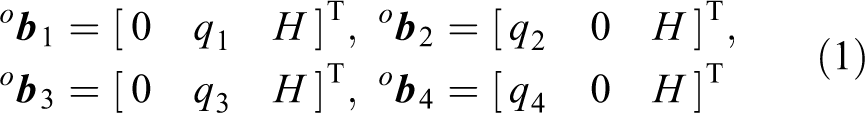
The position vector

where
The position vectors

where r and s are the X and Y components of the length between the upper joint of arm and the center of the adjacent R joint on the moving platform in the base frame, respectively.
The position vector

The closure of each subchain is given by

Solving the abovementioned equations, the inverse kinematic solutions can be obtained as
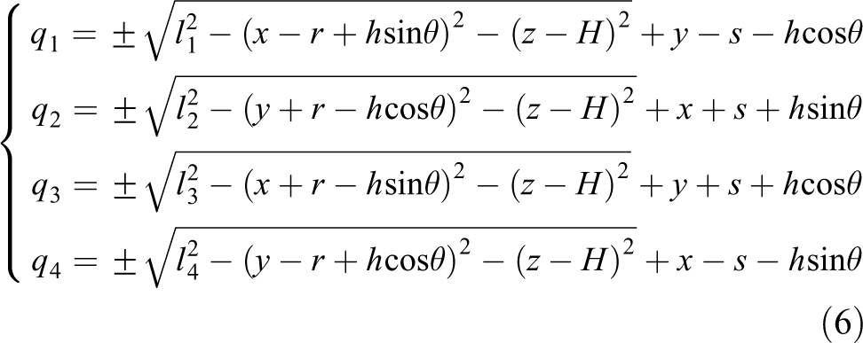
From equation (6), there are eight inverse kinematics solutions for a given pose of the hybrid mechanism. To obtain the inverse configuration, the first and the last of the signs “±” in equation (6) should be “−,” while the other signs “±” should be “+.”
Jacobian matrix
The velocity and acceleration of point p are given by

Differentiating equation (2), the velocity

where
From equation (8), the velocity

where
Furthermore, the actuation velocities can be expressed as

where
To derive the 6 × 6 Jacobian matrix and 6 × 6 × 6 Hessian matrix, the poses of the constrained wrench should be determined, there are two constrained couples on moving platform. A constrained couple of each subchain can be determined by the geometrical approach,
41
the direction unit vectors of two constrained couples of the moving platform are
Since the constrained torque limits the movement of platform, it does not provide any power to the moving platform. Thus, an augmented velocity equation is derived as

The inverse velocities of the mechanism can be solved from equation (11) as follows

where
The angular velocity of point

where
The velocity of the point
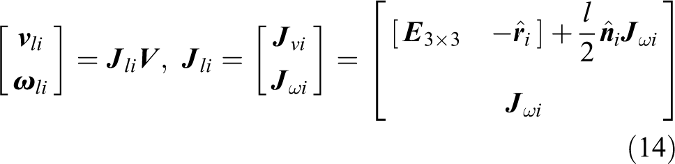
where
Similarly, the velocity of the lateral bar can be derived as

where
Hessian matrix
Differentiating equation (9), the acceleration

where
The actuation accelerations can be expressed as

where
By differentiating equation (19), the inverse/forward accelerations of the mechanism can be solved as follows

where
Differentiating equation (13), the acceleration of point
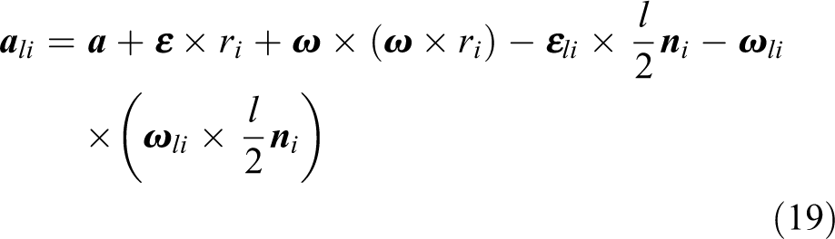
Differentiating equation (13), the angular acceleration of point

Dynamics modeling
Using the Newton–Euler equation, the inertial force and moment of each moving part can be determined by neglecting the friction force. Let m 1,m 2,m 3, and m 4be the masses of the moving platform, lateral bar, arm, and slider, respectively.
Based on the virtual work principle, the dynamic model of the hybrid mechanism can be expressed as

where
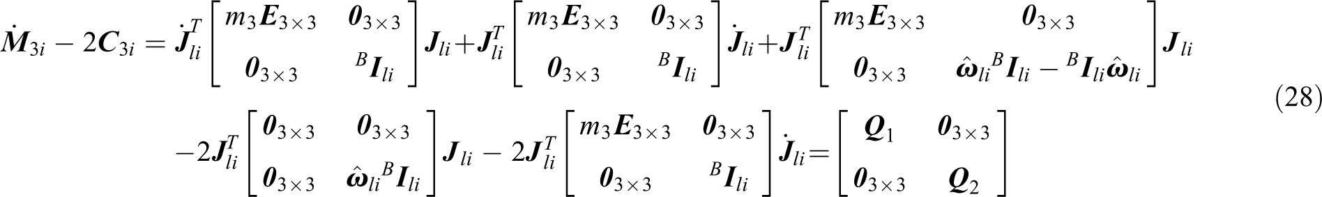
Equation (21) can be simplified as

where


where
To simplify,
Property 1
Property 2
To prove

where

It is obvious that
Then,

where

In order to prove
where
Since
Similarly, since
Furthermore, as
Therefore,
Similarly, we can prove
Controller design
The proposed strategy is composed of TSMC, adaptive fuzzy logic, and a nonlinear observer. The feedback of the nonlinear observer is used as an input in the TSMC. In addition, the adaptive fuzzy logic is used to update the switching gain of the TSMC.
The block diagram of the proposed controller is shown in Figure 3, which is composed of three subsections including a user input part, a controller part, and robotic system. The user input part is used to compute the three signals

The block diagram of the proposed controller.
TSMC design
The tracking control problem in the task space is to find a control law so that the position tracking error


where
We can define command vectors


The sliding surface can be defined as

where
The time derivative of equation (33) is

If system states come up to the fast terminal sliding mode, that is,

The ith element of equation (35) can be expressed as

where
If equation (36) has an equilibrium point at

Substituting equations (33) and (34) into equation (22) gives

where

Thus, equation (38) becomes

To make the position error converge to zero in a finite time, the following control law gives

where
Remark 1
Remark 2
Remark 3
Remark 4
Proof
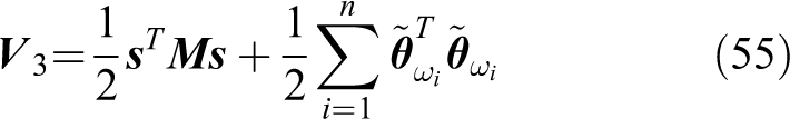
The Lyapunov function for TSMC is

Differentiating

Applying property (P2) and substituting equation (38) into equation (43), the following equation leads to

Observer design
To design a nonlinear observer to observe external disturbances, the following parameters are defined as


where
An observer can be designed as

where
The Lyapunov function for the observer is
Assuming that the disturbance signal is slow time varying, that is to say

Substituting equation (47) into equation (49) yields
where
To make sure that

Through the abovementioned analysis, the stability of the observer can be proved, the observer is asymptotic convergence to zero.
Adaptive fuzzy algorithm design
An adaptive fuzzy logic system (AFLS) is considered as an effective method to eliminate the chattering in the literature. 42 Hence, AFLS is introduced here to approximate the switching gain and to eliminate the chattering. AFLS consists of a knowledge base, a fuzzifier, a fuzzy inference engine, and a defuzzifier. The knowledge base for the AFLS is comprised of a series of fuzzy If-Then inference rules as follows:
Rule i: IF
where m is the rule number.
Both
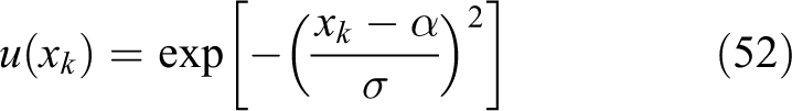
where α represents the membership function’s center and σ determines its width.
The ith-output of fuzzy logic system can be defined as

where
Lemma 1
Let

Stability analysis
Proof
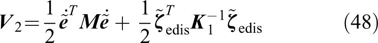
Choose a Lyapunov function as
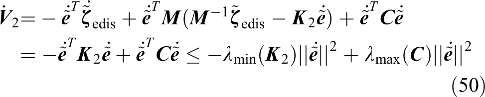
Applying property (P2), the time derivative of the Lyapunov function is

Substituting equation (44) into equation (56) gives
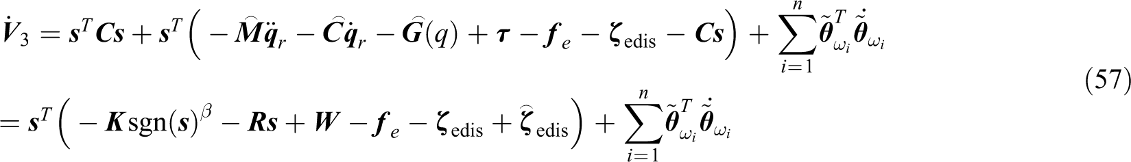
where

To satisfy the inequality

Substituting equation (59) into equation (58) yields

Applying Lemma 1, we obtain

Substituting equation (61) into equation (60) gives

where
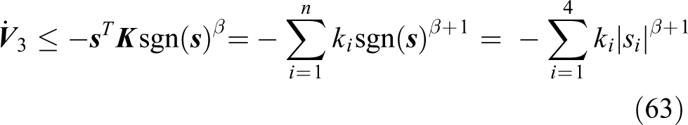
Since

where
The continuous AFSTMCO will be reached in finite time

From equations (37) and (65), it follows that

Thus, the tracking errors and its derivatives converge to zero in finite time.
Simulation
To demonstrate the performance of the proposed algorithm, simulations of trajectory tracking on the 2-(PUU)2R mechanism are performed using MATLAB [version: MATLAB 2014a] software. The related geometrical and inertial parameters of the mechanism are given in Tables 1 and 2.
Related geometrical parameters of the 2-(PUU)2R mechanism.

Related inertial parameters of the 2-(

To compare the simulation results, two trajectory tracking experiments were conducted. In addition, three control algorithms for the experiments are examined. The other popular control algorithms for the simulations such as PID and SMC are compared with the proposed algorithm, and their control vectors are given by:

where
For the purposes of comparison, three control algorithms including tradition PID, SMC, and the proposed approach were used to control the system, respectively. The control gains of the three schemes are listed in Table 3. Based on the abovementioned parameters, the simulations are shown in Figures 4 to 6. All of the controller gains are tuned in such a way that the three controllers’ performances are quite satisfactory in the ideal situation and almost equal in terms of their tracking errors.
Control gains of the three controllers.

SMC: sliding mode control; PID: proportional–integral–derivative.

The circular trajectory tracking result. PID: proportional–integral–derivative; SMC: sliding mode control.

The circular tracking error of the first experiment. (a) X-axis and (b) Y-axis. PID: proportional–integral–derivative; SMC: sliding mode control.

Joint driving force of the first experiment. (a) The first joint, (b) the second joint, (c) the third joint, and (d) the fourth joint. PID: proportional–integral–derivative; SMC: sliding mode control.
In the first experiment, considering the task space and singularities of the mechanism, the moving platform is required to move along with a circular path, and the external disturbances are assumed as to be

where x(t), y(t), and z(t) denote the displacement of the moving platform along the X, Y, and Z axes, respectively.
The tracking trajectory of point p of the moving platform is shown in Figure 4. For comparison purpose in different controllers, obviously, the tradition PID and SMC obtains a terrible tracking performance because of the constant switching gain and they did not consider the dynamic effect of varying payload. The error of the tracking trajectory by the AFSTMCO could become smaller.
The actual trajectory tracking errors along the x and y directional movements are shown in Figure 5. Compared with the other two controllers, the proposed controller has an ability to decrease the error of trajectory tracking of the moving platform of the hybrid mechanism effectively, which can keep the error in the range of 0.3 mm. It is observed that both the maximum control error and the steady-state error tolerance have been significantly reduced, and the settling time has been significantly shortened. In addition, a smoother trajectory tracking can be obtained by the AFSTMCO than the other two controllers.
The AFSTMCO is used to approximate the switching gain of SMC. As shown in Figure 6, joint force generated from the PID and SMC are compared, and a smooth input force signal can be obtained by the AFSTMCO than the other two controllers. Also, the chatter generated by the switching gain can be eliminated effectively.
Based on the simulations in Figures 4 to 6, the AFSTMCO can achieve a better trajectory tracking performance and eliminate the chattering of the SMC.
In the second experiment, the moving platform is required to move along with a circular with a high frequency. The following desired trajectory is chosen as

The circular tracking error of the second experiment is shown in Figure 7. Compared with the other two controllers, the proposed controller exhibited the ability to decrease the error of the high-frequency reference trajectory. It is observed that both the maximum control error and the steady-state error tolerance have been significantly reduced, and the settling time has been significantly shortened. Moreover, the joint forces generated from three controllers are shown in Figure 8, which shows that a smooth input force signal could be obtained by the AFSTMCO.

The circular tracking error of the second experiment. (a) X-axis and (b) Y-axis. PID: proportional–integral–derivative; SMC: sliding mode control.

Joint driving force of the second experiment. (a) The first joint, (b) the second joint, (c) the third joint, and (d) the fourth joint. PID: proportional–integral–derivative; SMC: sliding mode control.
The errors between simulation results were computed for all experiments. The cost function for the tracking position error is defined as

where ex (n), ey (n), and ez (n) are the displacement errors along X-, Y- and Z-axis of the nth sample obtained from the simulation results, restrictively. eα (n) is the rotational error around the Z-axis. N is the number of the sample.
Table 4 gives the cost function values obtained from the two experiments. We can observe that the cost function for the tracking position error of the proposed controller is even smaller than that of SMC, as well the high frequency reference trajectory. As a result, the proposed control method provides a superior tracking performance.
The cost function values for the two experiments.

AFSTMCO: adaptive fuzzy terminal sliding mode controller with nonlinear observer; PID: proportional–integral–derivative; SMC: sliding mode control.
Conclusion
This article presented an improved 2-(PUU)2R hybrid mechanism, whose actuators have orthogonally arranged in the normal plane component, which renders the motions of the plane more easier to perform. Based on the kinematic relation, the 6 × 6 Jacobian matrix and 6 × 6 × 6 Hessian matrix are derived. The inverse/forward velocity and acceleration of the hybrid mechanism are solved. Moreover, the dynamic characteristics are determined so that numerous control algorithms applied for the serial mechanisms can be easily extended for the hybrid mechanism.
The AFSTMCO for the hybrid mechanism to achieve a precise trajectory tracking is designed. The simulation results show that the proposed control method provides a superior tracking performance in the presence of model uncertainties, varying payloads, and external disturbances. Compared to PID and SMC, both the maximum control error and steady-state error tolerance of the AFSTMCO have been significantly reduced, and the settling time has been significantly shortened. In addition, the proposed control method can be used for pick-and-place robots to track the high-frequency reference trajectory.
In the future work, the design and validation methodology proposed in this article could extend to other types of hybrid mechanisms as well.
Footnotes
Declaration of conflicting interests
The author(s) declared no potential conflicts of interest with respect to the research, authorship, and/or publication of this article.
Funding
The author(s) disclosed receipt or the following financial support for the research, authorship, and/or publication of this article: This work was supported by the National Natural Science Foundation of China (Grant No. 61473112).