
Abstract
Robotics is increasingly involving many aspects of daily life and robotic-based assistance to physically impaired people is considered one of the most promising application of this largely investigated technology. However, the World Health Organization reports that, so far, only 10% of people in need can get access to the so-called assistive technology also due to its high costs. This work aims to tackle the aforementioned point presenting an innovative control strategy for a low-cost hand exoskeleton system based on surface electromyography signals. Most of the activities of daily living are, in fact, carried out thanks to the hands while the exploitation of surface electromyography signals represents a non-invasive technique in straightforwardly controlling wearable devices. Although such approach results deeply studied in literature, it has not been deeply tested on real patients yet. The main contribution of this article is hence not only to describe a novel control strategy but also to provide a detailed explanation of its implementation into a real device, ready to be used. Finally, the authors have evaluated and preliminary tested the proposed technique enrolling a patient in a single-case study.
Introduction
During the last decades, robots have been becoming increasingly more pervasive in many aspects of the human life: industry, goods handling, and transportation mostly. Lately, as other sectors, also the health care system has been consolidating the use of robotic devices as part of the so-called assistive technology. The World Health Organization (WHO) identifies assistive technology as the set of all the products that “enables people to live healthy, productive, independent, and dignified lives” whatever their condition. Examples of standard assistive technology are hearing aids, wheelchairs, communication aids, spectacles, prostheses, pill organizers, memory aids, and so on. According to the last WHO action plan on disability, 1 people who need at least one assistive device are more than 1 billion all over the world. However, only the 10% of the ones in need have access to these products due to, among the other causes, “high costs and nonexistent or inadequate funding mechanisms.” The work behind this article was born with the intention of intervening in this subject, making the assistive technology more accessible and affordable by developing low-cost robotic assistive devices. Many are the ways in which robotic exoskeletons can help, in this specific case, the focus is on hand exoskeleton systems (HES) to help and assist people with hand(s) impairments.
The hand is one of the most important providers of independence in carrying out the activities of daily living (ADLs). From the engineering point of view, it also represents a major challenge both for the mechanical design and the control strategy because of its complex anatomy, the high dexterity tasks it can accomplish and the wide set of movements it can carry out. The attempt to integrate robotics aspects with assistive products represents, nowadays, one of the trickiest aspect of the human–robot interaction field. As a matter of fact, they have to be designed to share the environment and to physically interact with human users affected by disabilities for long periods of time and, for these reasons, they have to meet strict requirements in terms of wearability, safety, and comfort. In this complex scenario, the exploitation of topology optimization methods for the mechanical design and the use of rapid prototyping technologies for the manufacturing phase have proved to be valid tools for the development of a well-performing prototype of HES (described in section “Hand exoskeleton system overview”) even in a low-cost perspective.
Unlike passive orthosis, 2 which, as the name suggests, do not present active elements (e.g. motors), assistive robotic devices generally incorporate power supply circuits, electronics (e.g. sensors, micro-processors), and actuators and, thus, need to be carefully controlled to provide an intuitive and safe utilization. Recent literature suggests, as one of the most promising emerging control strategies, the exploitation of electromyographic (EMG) signals. These signals, scientifically characterized starting from the end of the 70s 3 and placed at the heart of a big project by the European Community in late 90s, 4 are produced by the motor units (the set of motor neurons and the skeletal muscle fibers energized by those motor neurons) and manifest themselves as a potential difference that can be measured both with intramuscular and epidermal (surface) sensors. When a muscle contracts, fibers’ membranes are interested by continuous phenomena of depolarization and repolaritazion that induce an electromagnetic field in their proximity that can be recorded by means of an electrode. EMG signals present amplitudes that vary in a range from microvolts to millivolts, a frequency range from few to, roughly, 500 Hz, and a stochastic behavior; in addition, their collection is affected by several noise issues (e.g. noise coming from the electronics equipment itself, ambient noise, motion artifacts, electrocardiographic artifacts, and cross talk). 5,6 During the past years, to successfully use such signals for controlling robotic devices, many and different techniques have been investigated for classifying users’ intentions starting from the different patterns of EMG. 5 –16 At the same time, other research works have focused on attenuating the impact of the aforementioned possible measurement disturbances. 17 –20 The common base idea, among all the just cited control strategies, is to collect surface electromyographic (sEMG) signals, as it is a less invasive technique with respect to the intramuscular measurement, segmenting them into time windows of an appropriate length 21 and, for each segment, applying a filtering action and extracting time domain or frequency domain features, or a combination of both types. These features are used to feed specifically designed classifiers (e.g. neural networks, support vector machines, hidden Markov models, and so on) that run pattern recognition algorithms. The existence of a biunique relation between the EMG patterns and the corresponding gestures is reasonably assumed as true. Classifiers output is the prediction of the user’s intention which is used as a control command for the HES to reproduce the correlative movement.
Although literature presents many studies about EMG classifiers with encouraging results for what concern their accuracy, few are instead the ones regarding the implementation of such decision-making algorithms on HES. The aim of this article is to present the application of an EMG-based control strategy specifically thought for a low-cost HES internally developed (see section “Hand exoskeleton system overview”) to provide a fully wearable assistive device to assist hand-impaired people in their ADLs. At the end of the article, it will be also reported and discussed the qualitative results (no statistical analysis has been carried out) of two grasping tests conducted during a single-case study. These tests have been performed with the aim of preliminary evaluating the usability of the system and paving the way for future statistical analysis on a bigger test sample.
The article is organized as follows. The remainder of this section will outline the main related works and will discuss the main contributions of this article. Section “Hand exoskeleton system overview” gives a description of the mechanical system and the electronics of the test-bench exoskeleton. Section “Control architecture” presents the proposed control strategy. Section “Experimental tests” explains the experimental protocol used for the tests session and shows the achieved results. Section “Conclusions and future developments” discusses the results and explains further developments.
Related works
There are not many research works available in literature regarding an actual implementation of an EMG-based control strategy to a HES. This might be ascribed to the obvious need of having a safe robotic device ready to be worn and used by patients and to the observation that the changes in EMG patterns that the use of an exoskeleton entails are not negligible. In addition, the HES mechanical architecture itself represents an implicit limit to the complexity of the classification strategy. The number of degrees of freedom (DOFs) allowed by the mechanism, the number of motors, which in turn determines the number of independent fingers, and the requirements of wearability and real-time classification are indeed limits both for the number of reproducible users’ intentions and for the computational power available to run the classifier. This is why the refined EMG-based classification strategies suggested by literature give way to simpler techniques when it comes to the application to a real device.
Main related works available in literature will now be described on the basis of four main points: number and positioning of the EMG sensors (intended not only as the place where the sensors are located but also as the positioning act itself), classification phase (characterized by the number of classifiable gestures, the nature of the extracted features, and the classification criterion), actuation methods (separating between control systems that wait for a triggering action and those which require a continuous effort), and wearability of the system (intended as the possibility to be totally worn). Type of EMG sensors and the field of application (i.e. assistive or rehabilitative) will not instead be taken into account as discriminating parameters since the focus will be on the classification and the control strategy rather than on the characterization of the signals and of the collecting method.
Ochoa et al. 22 presents a control strategy that uses sEMG signals collected from the extensor digitorum and from the flexor digitorum. Sensors, whose number is not specified, are placed in their particular position by an external supervisor. The control algorithm is meant to recognize two gestures, opening and closing of the entire hand, comparing the magnitude of the signals with their corresponding fixed voltage thresholds, which is somehow set depending on the user. The actuation is carried out in percentile steps of 10% of the maximum range of motion (ROM). The classification code runs on a custom printed circuit board (PCB).
The strategy proposed by Ho et al. 23 collects sEMG from the extensor digitorum that is again in charge of detecting opening gestures, and it delegates the management of the closure to the abductor pollicis brevis signal. Similar to the previous work, two sensors are located through an external intervention on the specific muscles, and the classification is achieved by means of two thresholds (20% of the relative maximum voluntary contraction). The opening and closing gestures, which involve all the fingers, are entirely executed once the triggering action has been detected. The exoskeleton control box is fully wearable and can be connected to a remote control used by therapist to switch between different training modalities.
One of the last applications of an EMG-based control system to a HES is presented by Meeker et al. 24 They use a commercially available elastic EMG armband, composed of eight bipolar surface sensors. Unlike the two previous works, the use of the armband allows for a simpler wearing that does not require the intervention of an expert external person (since the armband does not have to be positioned in a precise way). For the classification phase, a random forest algorithm has been used. They feed the classifier with the eight raw EMG signals coming from the armband and it outputs a probability that the user’s intention is to open or close the hand (acting on all the five fingers at once). Finally, they filter the classifier’s outputs with a median filter, characterized by a time constant of 0.5 s, and they compare these new outputs with two thresholds to determine whether the hand has to be opened or closed. No clear references are made to the hardware that runs the classification algorithm nor to the actuation method.
Finally, a different approach is followed by Leonardis et al. 25 Although it is quite far from the other works and from the objectives of the work behind this article, this study anyway deserves attention as it can be used as a basis for future developments. They propose a system for bilateral rehabilitation that uses signals coming from the non-paretic hand to reproduce the same movements and forces on the paretic one by means of a HES. The sensors are, once again, placed in position by an external person but, this time, not on the limb influenced by the exoskeleton. The authors have then exploited a light neural network, implemented on a desktop PC, as classifier. Input of the neural network are full-wave rectified sEMG signals whose muscles of origin are the extensor digitorum, the flexor digitorum, and the abductor pollicis brevis.
Discussion
All the related works, except for the last one which does not specify this point, describe the application of a classifier which can distinguish among three hand states, open, close, and rest (or relax state) starting from sEMG signals measurements. The first two present two similar very simple classifiers running on an embedded control system; the third and the fourth describe two more sophisticated techniques of machine learning running on external equipment. Aside for Meeker’s work, they need a trained external person to place in position the EMG sensors. The number of total sensors varies in a range from two to eight. Only Ochoa’s study explicitly shows a non-triggering actuation method.
The main contribution of the strategy proposed in this article is to offer an approach that goes beyond some of the limits of the aforementioned related works by representing a convenient trade-off among the previously exploited strategies. This work focuses, in fact, on the development of a novel technique that involves the use of two sEMG sensors placed in specific positions and of a fully wearable embedded system, the classification among three hand states (hand open, close and rest), and a non-triggering actuation method. At the same time though, it takes advantage from a more advanced classification criterion with respect to those exploited by the fully embedded systems available in literature.
HES overview
Mechanical structure
In a previous work, Conti et al. 26,27 describe the base HES on which the proposed control strategy has been implemented. The overall structure and kinematics have been then modified by means of an optimization-based design strategy, presented by Bianchi et al., 28 to produce the system visible in Figure 1. This exoskeleton has been designed to help people with deficiency in opening the hand whether the problem was of chronic or traumatological origin. It is supposed that the user can exert, voluntarily or not, a certain amount of force when closing the hand while the opening is impeded by an unnatural tendons’ retraction and/or to a dysfunction of the extensor muscles.

The system is composed of four planar finger mechanisms, which act on the four long fingers, and a control box that contains the actuator and the control system (board and auxiliary electronics). It has a total of eight independent DOFs, two per finger. As shown in Figure 2, each mechanism presents one active and controlled and one passive DOF, which allow respectively for the flexion/extension and the abduction/adduction movements of the metacarpophalangeal (MCP) joint. As well as improving the device comfort, the passive DOF is required to align the plane of action of the mechanism with the flexion/extension plane of each finger.

The figure shows the lateral (a) and top (b) view of the finger mechanism. The 1-DOF kinematic chain acts on the flexion/extension plane (a) of each finger, while the entire mechanism is let free to rotate around the abduction/adduction axis to follow the finger movements (b). The actuated and the unactuated DOF are highlighted in red. DOF: degree of freedom.
An automatic scaling procedure customizes the kinematics of each finger mechanism to adapt the hand exoskeletons to different patients’ hand biomechanics and results in a straightforward adaptability to several users. In addition, the high customization of the 1-DOF kinematic chain leads to a good trade-off between accuracy and functionality in reproducing the patient’s finger trajectories. The average ROM (among different hand sizes) for the MCP rotation is about 80°. Each finger mechanism interfaces with the related finger only on the intermediate phalanx and is positioned on top of it not to be bothering during objects handling.
The whole system is actuated by a single servomotor that is in charge of opening all the four long fingers at once by simultaneously pulling each finger in extension by means of a cable connected to the finger mechanism. The actuator manages, instead, the hand closure by releasing the cable and allowing for a controlled but unactuated fingers’ flexion. This means that no flexion forces are applied to the fingers by the HES during closure. Since the length of the required cable is different between the finger and finger, a specific cable-driven transmission has been designed to achieve a common angular velocity. Both the transmission and the actuation system are placed on the hand backside.
The exoskeleton is designed to exert about 15 N applied to the contact point of each finger, at the same time. This value has been identified as a suitable force output for the manipulation of common objects during normal activities. In fact, considering a weight target up to 1.5 kg and a coefficient of friction of 0.255 (mean value), a force of 14.7 N per finger has been considered as appropriate to manipulate several objects. 30 Merging together the aforementioned requirements in terms of mechanical characteristics with the ones of lightness and cheapness, the 3-D-printing of all the mechanical parts in Acrylonitrile–Butadiene–Styrene (ABS) has proved to be a remarkably convenient solution. The system, made of the 3-D-printed mechanical parts and the metallic parts (screws, bolts, and pins) required for the assembly, has a total weight of about 120 g and a total cost of about €300.
Electronics
According to the guidelines of low cost on which this prototype was born, but also to the stringent constraints that this scenario imposes in terms of encumbrance and lightness, the electronics of the system has been reduced to the minimum necessary. The selected components are listed below.
MyoWare Muscle Sensors from Advancer Technologies (United States) 31 have been chosen for collecting EMG signals. Small (20.8 × 52.3 mm2) and low-powered devices (up to 6.3 V and to 14 mA), they measure the electrical activity of a muscle, outputting either raw or already filtered EMG signal. Their datasheet specifies that the filtering action they perform consists of an amplification, a rectification, and an integration phase to obtain an envelope of the signal. They can be powered directly from a 5-V pin of a whatsoever micro-controlled board and their output can be read through any I/O pins.
HS-5495BH High-Torque Servo from Hitec (United States) 32 has been selected to be the only actuator of the system. With a size of 39.8 × 19.8 × 38.0 mm3 and weight of about 44 g, can output a maximum torque of 0.735 Nm and a maximum angular speed of 6.67 rad/s if powered with 7.4 V. Before the use, the actuator has been modified to allow for its continuous rotation: the mechanical stop has been removed and its internal driver has been replaced with the Supermodified V3.0 for RC-servos from 01 Mechatronics (Greece), 33 which consists of a direct current (DC) motor controller and a 15-bit magnetic encoder. This modification has also allowed to actively control the actuator’s speed and for communicating with the motor through the I2C protocol.
One MagEnc V3.0 Low Rev from 01 Mechatronics, 34 a 15-bit magnetic encoder, has been place in correspondence of the MCP joint for collecting the angular position and velocity of the index finger. The available lateral space makes the index mechanism the perfect candidate for the housing of the sensor. Since all the four long fingers are moved together by the exoskeleton, the measurements coming from the index finger are assumed consistent also for the others. Its standard configuration involves the use of the SPI protocol to communicate with it, but it has also been modified to communicate through the I2C protocol.
The Arduino (United States) Nano board from Arduino 35 has been chosen to be the embedded microcontroller of the system. This small board (18 × 45 mm2), based on the ATmega328 from Atmel (United States) (16 MHz-clock processor, 8-bit AVR architecture, 32 kB of flash memory, 2 kB of SRAM memory and 1 kB of EEPROM memory), offers the possibility to easily connect and communicate to a wide variety of electronics devices included, of course, all the aforementioned ones.
All the presented components, except for the MyoWare Muscle Sensors, have been integrated together and housed in a box on the back of the user’s hand attached to a custom PCB, as shown in Figure 3.

The figure shows the electronics schematics that connects the sensors and the motor to the custom PCB (a) and the actual integration and realization of the circuit (b). PCB: printed circuit board.
The total weight and the cost of the selected electronics are about, respectively, 80 g and €250.
Control architecture
Before going into the details of the control strategy, a brief outline of the common requirements for such kind of application is given.
As stated at the beginning of this article, assistive products have to be continuously used for long periods of time. Wearability, lightness, and freedom of movement therefore remain important requirements to be met also for the control system. This is translated into the necessity of having a fully embedded hardware even if, compared to desktop PCs, workstations, or industrial controllers, embedded systems offer less resources and computational power.
Intuitiveness and the responsiveness of the resulting control are also two important points. The former is achieved by exploiting the same signals that normally (i.e. by healthy subjects) would be generated to control the hand motion, the latter is instead the result of a control system that allows for a maximum delay of about 300 ms 36 between muscle activation and HES response. In addition, the problem of the high costs of such devices had to be tackled with a reasoned choice of materials and equipment.
As a result of the just mentioned reasons, a trade-off between high performance and computational lightness has to be achieved.
Control strategy
The device under examination, as described in section “Hand exoskeleton system overview,” is already mechanically optimized to track fingers’ trajectories and to follow the hand kinematics. The control system therefore has to focus mainly on determining user’s intentions and managing command actions. The proposed control strategy (see Figure 4) can be split in two main parts, a “classification loop” and an “actuation loop,” which are sequentially executed every 20 ms (i.e. at a frequency of 50 Hz). The first loop, which is the main focus of this work, takes care of classifying the user’s intentions relying on the measurements of the forearm muscular activity captured by the EMG sensors. Once the current user’s intention has been classified, the corresponding signal is passed to the second loop that translates it into appropriate control commands for the actuation system. In other words, 50 times per second, the muscular activation of the user is evaluated and translated into a command for the actuation system, trying to follow the user’s intentions. To achieve this, the HES wearer has to undergo a first training phase in which the classifier algorithm is taught to recognize different muscular signals issued by the user’s muscles during different hand movements. The user will then control the exoskeleton behavior by reproducing as close as possible the signals which have been used to train the classifier (this is usually a process that takes time to be mastered and that needs training also for the user).

The figure shows the block diagram of the overall control strategy. The two main loops, the classification loop and actuation loop, are enclosed in the dashed rectangles. The word “passed” after the “ROM check” block means that the exoskeleton has not reached the limit of the ROM and, thus, the motor can keep running; the word “passed” after the “grasp check” block means, instead, that an object has been grasped and, therefore, the motor must be stopped. ROM: range of motion; EMG: electromyography.
Classification loop
The human hand can perform lots of different movements and most of them require high dexterity. These movements are allowed by muscles located in a small place within the forearm, very close to each other. The use of high computational power machines becomes, therefore, mandatory to achieve an accurate classification of every possible user’s intentions starting from sEMG signals. On the other side, linking an assistive device to such machines, which are usually heavy and fixed in place (e.g. workstations), is definitely far away from representing a wearable and a low-cost solution (since the machine itself will be account as part of the system).
In this complex scenario, a help comes from a recent study. Montagnani et al. 37 demonstrate what some of the previous works assumed as a simplification, that is the independent movement of the long fingers is not essential for most of the ADLs. An HES can therefore allow only for full hand opening and closing and still be an useful device capable of deeply improving the quality of life of hand-impaired people. This assumption not only validates the use of a single actuator, as described in the previous section, but also gives the scientific basis for the desired trade-off between the number of different movements to be classified and the limited computational power available on embedded low-cost hardware. Only hand opening, hand closing, and hand resting have then been considered as classifiable user’s intentions. The rest state represents the safe mode of the system because it does not imply any motion and it has been thought to enclose every EMG pattern different from hand opening and hand closing, including the ones coming from unwanted movements or external disturbances. The EMG envelope, which works well with microcontrollers’ analog-to-digital converters and which gives a qualitative idea of the level of activation of the muscle, has been selected as a representative feature to discriminate between the three gestures.
It has been chosen to use two EMG sensors placed on the antagonist muscle bands responsible for fingers’ extension and flexion, respectively, extensor digitorum superficialis and flexor digitorum superficialis. Figure 5 shows an example of the positioning of the EMG sensors attached to a healthy subject’s forearm. The use of two sensors is the result of the convergence of two different arguments: firstly, in a low-cost perspective and aiming at high wearability, a low number of sensors is preferable; secondly, two is the minimum number to consistently discriminate between the three possible classifiable intentions.

The figure shows the position of the sEMG sensors on a healthy subject forearm. An additional electrode is placed on the wrist bone and serves as reference. sEMG: surface electromyography.
Previous works, that focused on the classification of the user’s intentions during the use of a HES (as reported within the “Related works” subsection), exploit a technique that compares the signal coming from a single muscle to a lower threshold, which corresponds to a minimum level of muscle activation. Once the threshold has been exceeded, the corresponding input signal is sent to the actuation control. This makes the decision process 1-D. Although this method results to be very computationally lightweight and produces a decent control experience, it carries some intrinsic problems. Unwanted movements, little impacts with objects in proximity of the sensors, and/or sliding between skin and sensors might, in fact, produce the “so-called movement artifacts.” Since these artifacts are read, even though they are not, as remarkable muscle activation and since the triggering thresholds cannot be fixed to too much high values (which would entail a too tiring management of the system), these disturbances usually cause errors in the classification phase. Moreover, different hand or wrist movements might produce muscular activation that overcomes the same threshold (e.g. wrist flexion produces almost the same sEMG signal from flexor digitorum superficialis of fingers flexion because of cross-talk effect. It is instead less likely that the same thing happens considering a combination of two or more signals at the same time.
To reduce the incidence of such errors, the proposed control strategy aims at classifying the current user’s intention based on a combination of the signals coming from the two sensors. This way, the classification process becomes 2-D and a disturbance acting on a single muscle has less chances to lead to a misclassification. Instead of independently comparing the two signals to their corresponding lower thresholds, every sample interval a point, whose coordinate are the envelopes of both the sEMG signals, is plotted on a proper 2-D Cartesian plane, and it is tested against the belonging to a specific area.
A custom Qt Graphical User Interface (GUI), see Figure 6, has been designed to provide a user-friendly tool to be used to collect data, specify classification parameters, and to easily upload the tuned classifier to the microcontroller board from the PC where the tuning phase took place. In particular, it allows to collect sEMG data point concerning different gestures, to display them on a 2-D Cartesian plane on whose axis are reported the signals from the EMG sensors, and straightforwardly to draw the polygons which delimit the clouds of points belonging to the same gesture. The number of vertices, the shape, and the size of these polygons represent the main parameters to tune the classifier. Properly assigning these parameters on patient’s needs can improve classification accuracy and disturbances rejection. Tuning is hence meant to be done manually by a professional who has followed the patient during previous supervised physiotherapy sessions. It will also likely be performed at the hospital/rehabilitation center before the patient gets discharged.

The figure shows, on the left, an overview of the GUI while collecting data of different gestures and, on the right, a detail of the GUI during the drawing phase of the polygons. On the axes of the Cartesian graph are shown the envelopes of the signals coming from the two sensors. The buttons, visible on the left side of the overview, allow for the execution of various functions, including starting a new session, loading data from previous one, recording data, saving the current session, and uploading the parameters of the classifier to the Arduino. The GUI allows also for collecting an arbitrary number of different movements even if only two different polygons can be used so far during the classification phase. GUI: graphical user interface.
Going into details of the classification phase, a point-in-polygon algorithm, see Algorithm 1, has been chosen as the classifier. What this light code does is a ray-casting to the right. That is, it takes as inputs the number and the coordinates of the polygon vertices and the coordinates of a test point, and it verifies if the test point belongs to the area described by the vertices.
Point-in-polygon algorithm.

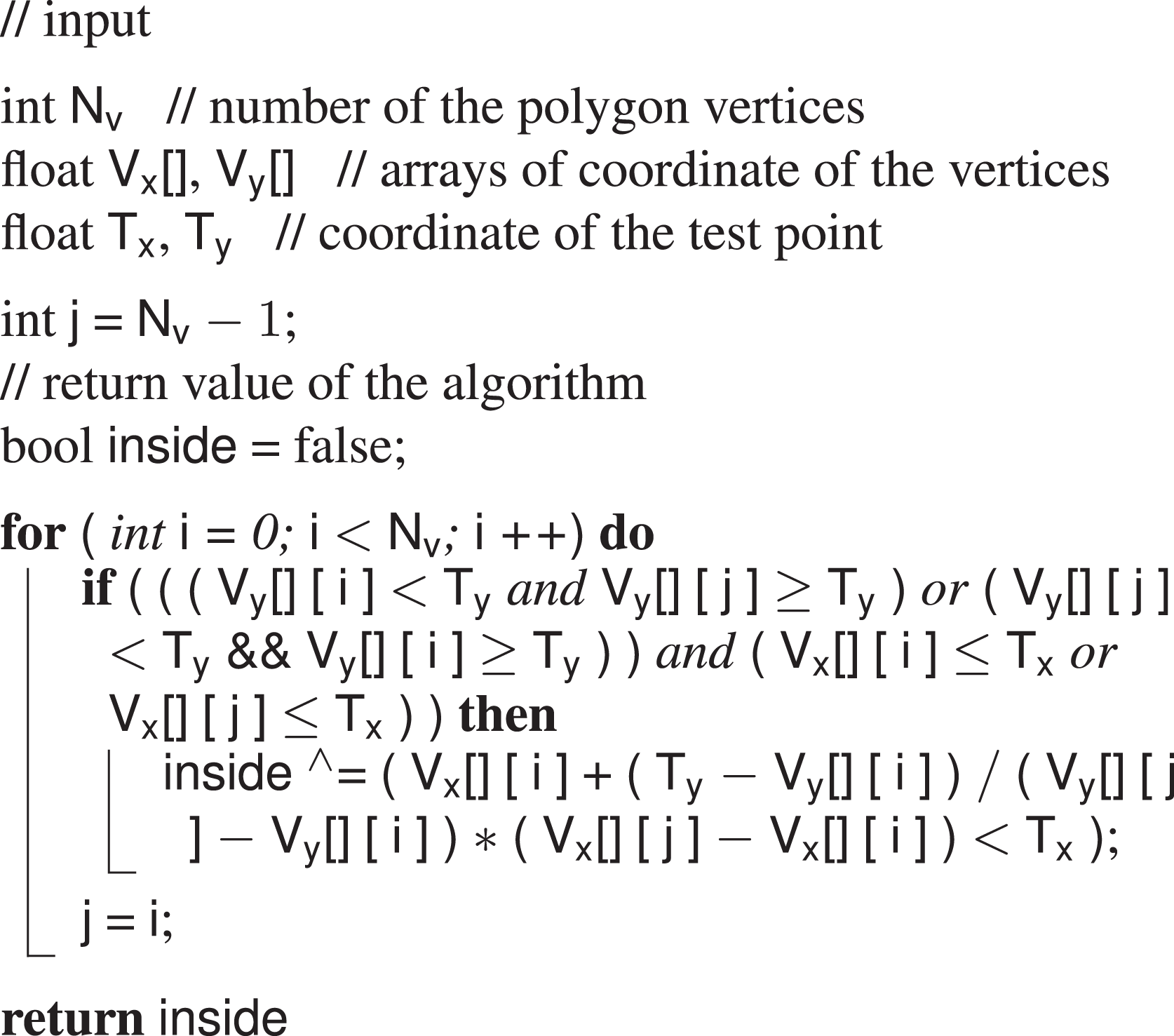
The number and the coordinates of the vertices come from the GUI and are stored in the EEPROM memory of the Arduino Nano board. The coordinates of the test point are instead the readings coming from the sEMG sensors and they are acquired every sample time. During each iteration of the code loop, the line drawn rightwards from the test point is checked against the polygon perimeter and the number of time this line crosses the edge is counted. Once the loop has ended, if the number of crosses is odd, then the point is inside, if an even number, the point is outside. The output of the classifier is computed and translated into actuation command once every loop. The HES control thus requires a continuous effort by the user. This choice has been made not to limit the actuation to preestablished movements but to let the user free to move the device to every intermediate position between the complete opening and the complete closing.
Actuation loop
The actuation is in charge of translating the classified user’s intention to a valid sequence of commands to be executed by the motor. If the detected user’s intention is to open the hand, the motor will start rotating clockwise, pulling the cables connected to every finger mechanism and resulting in the extension movement of the long fingers. If the classifier output is, instead, a closing intention the motor will rotate counterclockwise and will drive the closure of all the long fingers by releasing the same cables. Finally, when the classifier detects a rest intention, the motor is told to stop whatever it was doing before. To be noticed that, as stated at the end of the previous subsection, this command translation is performed 50 times per second. Therefore, to perform a smooth and natural movement, the user has to issue the same muscular activity for the whole time the desired motion lasts. Although it is a more tiring actuation technique with respect of those which just actuate the motion in response to a trigger command, it allows for a more complete control over the hand motion which, in the end, results in a more intuitive experience. Customized Arduino libraries have been used to interface with the HS-5495BH servo and the Supermodified motion control modules.
However, the motor commands are not generated only by the classifier. An outer loop is in charge to continuously check that, during functioning, the system does not overcome a fixed ROM. Real-time feedback on the angular position and velocity of the fingers is collected by means of the magnetic encoder mounted on the exoskeleton in correspondence of the MCP joint of the index finger. During a preliminary phase of tuning, the exoskeleton is donned by the patient, the actuator is left idle, and a physiotherapist moves the hand of the patient from the maximum opening to the maximum closure for several times. The average of the measurements identifies the anatomical limits of the user’s hand, in terms of rotation around the MCP joint of the fingers. Values corresponding to the complete opening state are used as reference. If these bounds are reached, the system stops and waits for the command that will move it back within the ROM (e.g. if closure bounds are reached, the system waits for an open command and rejects every other close commands).
An inner control loop, which is only active during hand closing, is meant to check instead whether a rigid or semi rigid object is grasped. This is done evaluating closing velocity of the index finger: when it drops below a fixed threshold while the motor is still releasing cable, it is reasonable to think that the hand has encountered an object or an obstacle. The control system intervenes stopping the motor, making it hold position and preventing the cable to be released more than necessary.
The necessity of actively controlling the grasping of an object has come into play during the first tests on healthy subjects. The authors have experienced that, if not properly monitored, objects handling with this cable-driven system, actuated through a sEMG-based control, might result very hard to achieve without repercussions. The mechanism, in fact, exploits and manages the user’s residual closing force without any force feedback about the interaction of the user’s hand with the environment. It is the user himself who decides when to stop the closing motion in correspondence of a good grasping. This is done by relaxing the muscles and letting the HES entering the rest state. To be noticed that the rest state of the exoskeleton does not correspond to rest state of the hand since it is assumed that, for the specific patients this system is designed for, a residual closing force is applied to the hand by tendons retraction. This means that even if the hand is relaxed, a force is anyway exerted on the object. Nevertheless, the transition from the close to the rest state has proved to be very difficult when interfacing with an object and it often made the motor run after the grasping, releasing cable when not requested. Although the inconvenience lasted just for a short period of time, it has been observed that also a small amount of cable released in excess usually introduced remarkable delays in further controlling actions and led to issues of interweaving.
Implementation issues and solutions
During the first laboratory tests, it turned out that executing a command action at 50 Hz results in stressful operative conditions both for the motor and for the user himself.
In fact, the control system forced the motor to execute every command coming from the classification loop even if it was the same as the previous one. This caused a quick overheating of the motor and consequently a loss of performance of the whole system. To reduce this stress factor, it has been hence decided not to overwrite the previous command if the status (i.e. the classified user’s intention) did not changed.
The user’s stress was instead related to the possibility of driving the exoskeleton actions with muscular signals mapped very close to the perimeter borders of the gestures areas. In these conditions, the point corresponding to the user’s intention can, in fact, easily jump from inside to outside the polygon and vice versa, as visible in Figure 7, under the effect of noise or little modifications in muscle activation, even if the actual intention does not change. Since the motor is continuously told to move (when the point is inside the polygon) and stop (when the point is outside the polygon), a glitchy actuation is the undesired result if no filtering actions are implemented. To mitigate this problem, the control action has been modified adding a sort of memory of the past command and of the last classified intentions. The classification phase has not been modified and the classification loop keeps outputting the estimated current user’s intention. However, the classifier output is no longer translated directly into a motor command, but it is instead added to a vector containing the last four classified user’s intentions and the present one. Each time a new element is added to the vector, the oldest one is removed. The vector size, for a corresponding time window of 5 × 20 = 100 ms (the action in execution does not fit into this calculation), has been chosen not to introduce too much latency, providing a still responsive control experience for a real-time application. The currently executed intention is stored in a separate variable. A customized filtering action is applied to this variable and to the intentions vector to determine which command action has to be executed by the motor. First of all, each classifiable intention has been assigned to an integer number, such as the rest state is the number in between the other two


The figure shows a zoomed portion of the Cartesian plane of the GUI. The green ellipse highlights the area where points belonging to the same gesture jump in and out the polygon producing the glitchy control issue. Enlarging the polygon in order to include every point is not always a good solution to this problem, since it reduces disturbances rejection and it might lead to more misclassifications. GUI: graphical user interface.
Then, a fixed weight of 0.4 is assigned to the current executed intention, while other five weights, heuristically gathered from a unitary parabola (


where
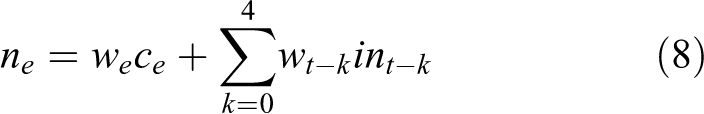
where
This has been done to achieve the effect of a windowed smoothing filter (window length = 100 ms, overlap = 20 ms) which strongly rejects single jumps from one intention to another, which gives much more importance to the latest classified intentions with respect to the oldest ones and which has a remarkable but not excessive inertia to changes: 40% of the output command depends in fact to the currently executed intentions. The selected weights are the results of laboratory tests which highlighted how the modified control experience turn out to be much smoother, less power consuming, and less fatiguing for the user.
Experimental tests
A single-case study has been carried out, in a rehabilitation center, to preliminary assess the impact level of the control strategy on the usability of the device when worn by a real patient. Given the de facto exploratory nature of these tests, the minute size of the test sample, and focusing more on demonstrating the possible application of the proposed approach than evaluating its actual performance, no statistical analysis has been performed so far.
One subject (male, aged 54, 1 + Modified Ashworth Scale 38 ) has been enrolled for the study. The patient suffers since birth from spinal muscular atrophy (SMA) type II, which is a neuro-degenerative disease with several possible different outcomes. In this specific case, SMA produced a selective damage to muscular extensors of both hands causing a clenched fist deformity and resulting in hand opening impairment due to tendons’ retroactions. The subject was provided with a written informed consent form and an information sheet. To provide a comfortable and high customized locking system on the patient’s hand, the ergonomics of the device has been improved by fixing the system on a splint directly manufactured on the user’s anatomy. Such a tailor-made interface solution, as visible in Figure 8, assures a stable kinematic coupling between the exoskeleton and the hand.

The figure shows the thermoformed plastic support, also known as “splint”, which has been used as a basis for the coupling between the patient’s hand and the HES. HES: hand exoskeleton systems.
Two EMG sensors have been placed, exploiting silver-chloride (Ag/AgCl) electrodes, on the extensor digitorum superficialis and on the flexor digitorum superficialis. However, since the selected subject was not able to provide strong signals concerning finger extension without feeling annoyance, it has been decided to use instead the remarkable cross-talk components from muscular activity coming from wrist motions. This decision has been made not to step away from the procedure previously tested on healthy subject during laboratory tests.
Single-case experimental design 39 methodology was chosen for the study: 10 objects of different sizes and shapes from those of daily use (i.e. an apple, a tangerine, a tennis ball, a mug, a 0.5-l bottle of water, a door handle, a spray can, a pot, a felt-it pen, and a smartphone) were selected for chronometric functional tasks tests.
Experimental protocol
In the following, the proposed protocol to evaluate the control strategy is described. The subject seated in front of a table on which the aforementioned objects have been previously placed within a fixed area. The subject, wearing the exoskeleton, has been asked to grasp each object and move it on a standard shoe box (12.5 × 28.5 × 10 cm3) placed 10 cm away from the initial position. For each object, a total of five trials have been conducted and the average grasping time was calculated. These test sessions have been accomplished twice in a week. Figure 9 shows the hand exoskeleton worn by the user during the testing sessions. A user-training approach has been followed to teach the patient to consistently produce EMG pattern corresponding to clear commands for the exoskeleton. The subject hence performed 1 h of training a day in between, wearing the exoskeleton, without being recorded.

The figure shows a free grasp (a), a spherical grasp (b), and a cylindrical grasp (c) performed by the patient using the exoskeleton. Although the overall geometry of the device has been changed to adapt to the splint, the kinematics and the functioning of the system have remained unchanged.
Results
Results of the two conducted test sessions are reported in Figure 10. The histogram reports on the x-axis the objects involved in the tests and on the y-axis the corresponding average grasping time. Tests results show that, in general, grasping time is longer as the shape get more complicated, for example, grasping an apple is quicker than grasping a felt-it pen. This can be attributed to the fact that, actuating four 1-DOF mechanisms at once, grasping an object with an irregular shape might require more time to let the exoskeleton adapt to the uneven form. It is also worth noticing that lateral grasping arose to be more difficult than the vertical one. This difference can be seen comparing bottle of water grasping with the tangerine/tennis ball one: the latter required, in fact, less time despite a similar diameter of the grip. This can be attributed to many difficulties encountered by the patient to activate the correct muscles in the different positions (the exoskeleton weight itself is differently compensated).
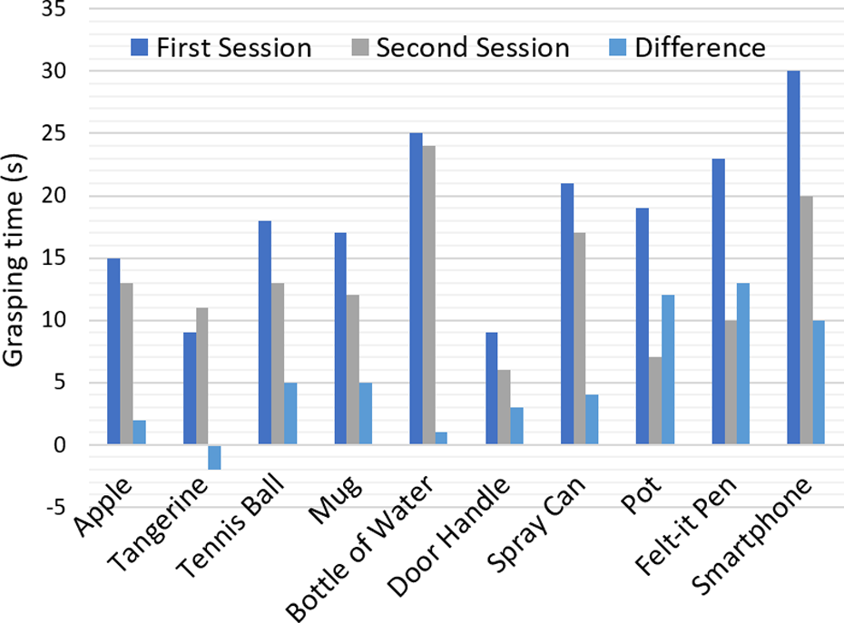
The figure shows the result of the chronometric tasks. The blue column refers to the first session, the gray one to the second session and the light blue one represents the difference between the two previous grasping times.
Although the average grasping times result to be quite high compared to reasonable standards for able-bodies, it can be noticed that they have overall become lower in only 1 week of training. The merit can be ascribed both to the practice, which has led the patient to the generation of better and more selective muscular signals, and to the major confidence in managing the system acquired by the user.
Conclusions and future developments
This article not only presents a sEMG-based strategy to control a lightweight (≃ 200 g) and low cost (≃ €550) fully wearable assistive HES but also describes its implementation on an embedded system that has been then tested on a physically impaired user during simulated ADLs. The classification phase of the user’s intentions and the integration of the strategy on a real device are the focal points on which the article is focused.
The novelty of this work lies in the fact that, comparing it with the related works available in literature, the studied solution shows a peculiar aspect which raise the bar of the current wearable assistive technology. Unlike other studies, in fact, the complexity of the classifier has been brought from a 1-D to a 2-D level. This way, it becomes more robust to external disturbances and more flexible to different intentions to be classified, as reported in the section “Control architecture.” The lightweight decision-making algorithm and procedure adopted make it still suitable for embedded applications which is another key point of the work.
Enhancing the classification capabilities and still achieving the possibility of integrating the code on a fully wearable system are encouraging signs for further developments.
Tests have been performed on a real patient to validate the discussed approach and qualitatively evaluate the capability of the user in exploiting the proposed control strategy during objects handling. A straightforward learning in managing the system has been suggested by the overall reduction of the grasping times between the two test sessions.
The authors are now working on overcoming the limits of the proposed solution.
First of all, since the conducted preliminary tests have assessed the goodness of proposed idea, a new testing campaign, on a larger test sample, will be scheduled and statistical data both for training and grasping time will be collected.
Secondly, a new actuation strategy will be investigated. To accelerate the grasping process and also to provide a more natural control of the hand motion, commanding the motor to move with a velocity proportional to something representing the overall level of activation of the muscles involved in the movement can be ascribed as a possible solution.
Thirdly, the classification phase will be further enhanced. The difficulties come out during later grasping might be got over by introducing inertial sensors capable of identifying the arm pose. This way, a later grasping can be detected and the control system will accordingly switch classification methodology taking into account gravity compensation. In addition, a new solution, based on a new microcontroller board, capable of executing more complex algorithms, has started to be designed. Some microcontrollers manufacturers have, in fact, planned to release in the next future tools capable of translating trained artificial neural networks directly to their embedded system. These tools are supposed to work with popular artificial intelligence frameworks (e.g. Caffe, CNTK, Keras, Lasagne, TensorFlow, theano) and their exploiting might push even further the level of “intelligence” in assistive products.
The new microcontroller board will be based on an ARM Cortex-M3 processor from STMicroelectronics (Switzerland) that will be totally dedicated to the classifier algorithm. The board will also house a LSM9DS1 inertial sensor from STMicroelectronics and an eight-channel EMG front end from Texas Instruments, which will manage the collection of the EMG raw signal from eight bipolar dry electrodes. To move toward an easier wearability procedure, while trying to increase the number of worn sensors, these electrodes will be encapsulated, as well as the microcontroller board, within an elastic band that will wrap up the forearm circumference. Something similar to current commercially available arm bands, together with a compliant dock stations, will be investigated and designed to allow the user for an independent donning of the sensitized system.
Footnotes
Declaration of conflicting interests
The author(s) declared no potential conflicts of interest with respect to the research, authorship, and/or publication of this article.
Funding
The author(s) disclosed receipt of the following financial support for the research, authorship, and/or publication of this article: This work has been supported by the HOLD project (Hand exoskeleton system, for rehabilitation and activities of daily Living, specifically Designed on the patient anatomy), funded by the University of Florence (UNIFI), Italy.
Supplemental material
Supplemental material for this article is available online.
References
Supplementary Material
Please find the following supplemental material available below.
For Open Access articles published under a Creative Commons License, all supplemental material carries the same license as the article it is associated with.
For non-Open Access articles published, all supplemental material carries a non-exclusive license, and permission requests for re-use of supplemental material or any part of supplemental material shall be sent directly to the copyright owner as specified in the copyright notice associated with the article.