
Abstract
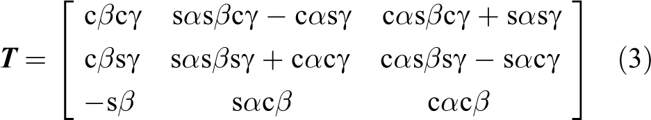
Singularity analysis is one of the basic problems for parallel manipulators. When a manipulator moves in a singular configuration, the motion and transmission performance are poor. In certain serious cases, the normal operation could be damaged. Based on the topology structure and kinematics analysis of a 2(3HUS+S) parallel manipulator, the Jacobian matrices were established. Then, the singular locus surface was obtained by numerical simulation. In addition, the relationship between the motion path curve and the singular locus surface was analyzed. In this study, α, β, and γ are the attitude angles that describe the motion of moving platforms. There is a nonsingular attitude space in singular locus surfaces, and the singular locus surface is a single surface in a small attitude angle range. The nonsingular attitude space increases as the absolute value of γ increases, and singularity could be avoided when γ is large. Furthermore, the motion path curve passes through the singular locus surface two times, and the two intersection points are consistent with the positions where the motion dexterity is equal to zero. This study provides new insights on the singularity analysis of parallel manipulators, particularly for the structure parameter optimization of the nonsingular attitude space.
Keywords
Introduction
A parallel manipulator is composed of at least two independent kinematic chains, which are connected by a moving platform and a fixed platform. It is a closed-loop manipulator with two or more degrees of freedom (DOF). Compared with the traditional serial manipulator, the parallel manipulator has many advantages, such as high rigidity, small error, and high precision. Furthermore, it has a complementary relation with the serial manipulator and expands the application field. 1,2 At present, most of the research studies are focused on kinematics, 3,4 dynamics, 5 –7 and performance analysis 8,9 of the manipulator; however, the analysis of singular locus surface is few.
When the manipulator lies in a singular configuration, 10 the Jacobian matrix loses rank, and its determinant is zero. According to the relation between the output and input, Gosselin and Angeles 11 divided the singularities of parallel manipulators into boundary singularity, interior singularity, and structure singularity. At present, singularity analysis is an inseparable part of the parallel manipulator. The research methods of singularity are divided into geometric algorithm and analytical algorithm. Geometric algorithm 12 –15 is mainly used to study the singularity of the manipulator, explore the mechanism of singularity, and so on. However, the results with the geometric method are incomplete in some cases. The analytic method where the Jacobian matrix loses rank 16,17 is used to analyze the singularity of the complex manipulator comprehensively. According to the intuitive curve, the trend of the singular locus could be observed directly. Thus, it is often used in the analysis of singular loci. Nawratil 18 concluded that the singular locus of the Stewart manipulator was a conic surface by analyzing the Jacobian matrix. Cheng et al. 19 established the 6-6 Stewart manipulator Jacobian matrix by taking the quaternion as the attitude parameter, given the three-dimensional (3D) description of the position and the attitude singular locus. However, an analysis of the relationship between the singular locus surface and the motion path is relatively few. In addition, the motion performance of a manipulator could be analyzed better by combining with the actual motion path curve. Cheng et al. 20 analyzed the singularity of a 3SPS+1PS parallel hip joint simulator, Shan and Cheng 21 and Zhang et al. 22 conducted some research studies on structural error, friction compensation control, and kinematic accuracy for the 2(3HUS+S) parallel manipulator, but the internal structure of the singular locus surface for the manipulator is not analyzed.
A 2(3HUS+S) parallel manipulator has three rotational DOF, and it is used for friction and wear tests of biomimetic hip joint materials. This article is organized as follows. In “Description of 2(3HUS+S) parallel manipulator and analysis of DOF” section, the description of the topology structure of the 2(3HUS+S) parallel manipulator and the analysis of DOF are presented. In “Establishment of the Jacobian matrix” section, we describe how the inverse kinematic model is built and how the Jacobian matrix is established. In “Singular locus surface of attitude parameters” section, the description and analysis of the singular locus surface of pose parameters are explained. In “Relationship between the singular locus surface and motion path” section, we present the analysis of the relationship between the singular locus surface and the motion path. Finally, conclusions of this study are provided in the “Conclusions” section.
Description of 2(3HUS+S) parallel manipulator and analysis of DOF
The topology structure and the virtual prototyping model of the 2(3HUS+S) parallel manipulator are shown in Figure 1. The parallel manipulator with three DOF is composed of two moving platforms (m 1 and m 2), three linear modules (LN 1, LN 2, and LN 3), a bottom base B, and a peripheral support. Each moving platform is connected with the linear modules by three HUS-type peripheral limbs and an S-type intermediate limb. A linear module has two sliders that can move up and down in the vertical direction. The slider is connected with its corresponding moving platform by a joint lever, which has one end as a Hooke joint (U pair) and the other as a spherical hinge (S pair). One end of the intermediate support is fixed on the bottom base and the other end is connected with the moving platform m 2 through a thrust bearing. One end of the ball spline is connected with the artificial hip joint in the moving platform m 2 and the other end is connected with m 1 through another thrust bearing. In addition, the moving platforms m 1 and m 2 are driven by three linear modules simultaneously. Accordingly, the two moving platforms of 2(3HUS+S) parallel manipulator have the same motion state, which ensures that the two artificial hip joints have the same mechanical characteristics. The two moving platforms for the 2(3HUS+S) parallel manipulator have many advantages, such as high efficiency and low test cost.

2(3HUS+S) parallel manipulator. (a) Topology structure and (b) virtual prototype.
The coordinate systems are shown in Figure 1(a), and they consist of a fixed coordinate system O-XYZ and two moving coordinate systems o 1-x 1 y 1 z 1 and o 2-x 2 y 2 z 2. The fixed coordinate system is established on the bottom base B at its center point O, with the line of Ob 2 as the Y-axis and the normal line of the fixed platform as the Z-axis. The moving coordinate system o 1-x 1 y 1 z 1 is established on the moving platform m 1 at its center point o 1, with line o 1 a 12 as the y 1-axis and the normal line of the moving platform as the z 1-axis. The establishment of the moving coordinate system o 2-x 2 y 2 z 2 is similar to o 1-x 1 y 1 z 1. Furthermore, the Y-axis, y 1-axis, and y 2-axis follow the right-hand rule. Two moving platforms are identical, and they establish an equilateral triangular structure with radius r. The bottom base also establishes an equilateral triangular structure with radius R, where R is the length of Obi .
The DOF of the parallel manipulator can be calculated according to the modified Kutzbach–Grubler formula. The DOF of the 2(3HUS+S) parallel manipulator can be described by

where M is the number of DOF, d is the order of the parallel manipulator, n is the number of members, g is the number of kinematic joints, fi is the number of relative DOF for each kinematic joint, τ is the number of redundant constraints, and ζ is the number of isolated DOF.
For the 2(3HUS+S) parallel manipulator, d = 6, n = 8, g = 10,
Establishment of the Jacobian matrix
The kinematic analysis methods of parallel manipulators mainly include the Euler transformation method, quaternion method, and Rodrigues parameter method. The Euler transformation method is simple and intuitive, and it does not need to be converted. Thus, in this study, the Euler transform method is adopted to analyze the kinematics of the 2(3HUS+S) parallel manipulator. For convenience, only the moving platform m 1 is analyzed; the analysis of the moving platform m 2 is similar to m 1.
In this study, α, β, and γ are used to describe the RPY angles. The RPY angles are the angles in which the moving coordinate system relates to the fixed coordinate system with the x 1-axis, y 1-axis, and z 1-axis, respectively. Based on the topology structure of the 2(3HUS+S) parallel manipulator, the motion branch vector is shown in Figure 2. The closed-loop vector equation for the manipulator can be described by

where

Motion branch vector.
In the moving coordinate system o
1-x
1
y
1
z
1,
For the first case,

where
For the second case,

where
The vertical velocity of the slider is rewritten as


The 2(3HUS+S) parallel manipulator has three HUS-type peripheral limbs,
According to the inverse kinematics of the parallel manipulator,


According to equation (7),

The singularity classification method was proposed by Gosselin and Angeles.
11
Singularity could be divided into three categories: Boundary singularity ( Interior singularity ( Structure singularity (
When analyzing the boundary singularity and interior singularity with the descending matrix rank method, the Jacobian matrix


where sα = sinα and cα = cosα. r and R are the radius of the hinge centers for the moving platform and the bottom base, respectively. z 1, z 2, and z 3 are the distances from the hooker joints on linear modules to the bottom base, they can be solved by the kinematics easily.
Through the numerical analysis and computation, the determinant of
The third singularity happens when the rank of the matrix
Singular locus surface of attitude parameters
Based on

Singular locus surface of 2(3HUS+S) parallel manipulator. (a) Elevation view and (b) overhead view.
According to the ISO14242-1:2002(E) standard for the artificial hip joint friction and wear testing machine, the motion law of the moving platform is as follows
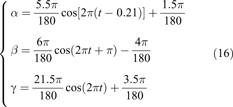
The motion path curve of the moving platform is gained by equation (16), and it is shown in Figure 4.

Motion path curve of moving platform.
Figure 3(a) shows that the singular locus is complex. Particularly, the complexity is more obvious when the attitude angle is large. In the movement process, the transmission performance of the 2(3HUS+S) parallel manipulator is poor. Furthermore, the singular locus surface is not a whole structure, but a discrete structure. It is worthy to note that the state of the singular locus surface is hollow. Similarly, there is a nonsingular attitude space in the singular locus surface. Additionally, the entire singular curved surface is distributed symmetrically. Figure 3(b) shows that the singular locus surfaces are not coincident in small attitude angles. In the course of normal operation, the 2(3HUS+S) parallel manipulator moves within these small attitude angles. Therefore, the singular locus is reasonable for the motion path curve. When γ lies in the small values, the singular locus surface trend of the manipulator is shown in Figure 5.

Singular locus surface of small attitude angle. (a) Singular locus of [−30°, 30°] and (b) singular locus of [−20°, 20°].
Figure 5(a) indicates that the singular locus surface is a single surface in small attitude angles. It is smooth in the middle and steep on both sides, as shown in Figure 5(b). In particular, when α and β are in the range of [−20°, 20°], it is most fit with the realistic motion range of the moving platform. The variation range of γ is small and changes within ±5°. The results also show that as long as the increase in the value of γ is within the allowable appropriate range, singularity would be avoided.
To observe the distribution trend of the singular locus surface conveniently, the singular locus surface is stratified. According to Figure 3(a), the singular locus surface is a symmetric structure in the vertical direction; therefore, only the upper part is analyzed. Based on the actual motion curve, the results of γ within 0–60° are shown in Figure 6.

Singular locus of each section. (a) γ = 0, (b) γ =5°, (c) γ = 30°, and (d) γ = 60°.
In Figure 6, the red curve is the singular locus curve, and the blue curve is the nonsingular attitude circle. The radius of the nonsingular attitude circle increases with γ increasing. Similarly, the nonsingular attitude ability becomes better. At the singular configuration where γ = 0, the curves cross each other. In addition, the increasing angle of γ will reduce the number of singular curves, and there are four single curves, which are disjoint to each other at 5°. In Figure 6(a), it is worthy to note that these curves do not cross each other except for the singular locus of γ = 0.
Relationship between the singular locus surface and motion path
After the motion Jacobian matrix is solved by equations (7) and (11), the motion dexterity index of the 2(3HUS+S) parallel manipulator can be defined as

where cond(
The smaller this value is, the worse the motion performance of the parallel manipulator is. The motion dexterity curve is shown in Figure 7, and the relationship between the motion path curve and singular locus surface is shown in Figure 8.

Motion dexterity curve of 2(3HUS+S) parallel manipulator.

Relationship between motion path curve and singular locus surface.
In Figure 7, the motion dexterity is equal to zero near 0.28 s and 0.72 s. Figure 8 shows that the motion path curve passes through the singular locus surface two times, and the intersection is just near the plane of γ = 0. The transmission performance of the two positions is relatively poor, and this is consistent with the two points at which the motion dexterity is zero. In addition, Figure 7 also indicates that the motion dexterity of the two points is small, and the same is true for the values near the two points. Therefore, the singularity of the manipulator should be for a region, not for some isolated points.
Conclusions
In this study, α, β, and γ are used to describe the attitude angles of 2(3HUS+S) parallel manipulator. On the basis of the topology structure, the singular locus surface is obtained by analyzing the Jacobian matrix and the relationship between the motion path curve and singular locus surface is described. The conclusions are as follows:
The state of the singular locus surface is hollow. In other words, there is a nonsingular attitude space in the singular locus surface. In a small attitude angle range, the singular locus surface is simplex. Meanwhile, this range is nearly consistent with the realistic motion.
Based on the stratified analysis of the singular locus surface, the nonsingular attitude space of the manipulator increases from the middle to both sides with the absolute value of γ becoming larger. Otherwise, at the plane of γ = 0, the complex singular loci cross each other and the Jacobian matrix loses rank. This position is just the singular configuration of the manipulator. Therefore, in the movement process, the values of γ should be kept large, and the manipulator cannot stop running at the position as much as possible.
The motion path curve passes through the singular locus surface two times, which is in agreement with the two points where the motion dexterity is equal to zero. Furthermore, the motion performance is poor near these points.
Finally, the results also provide a theoretical support for the structure parameter optimization of the nonsingular attitude space.
Footnotes
Declaration of conflicting interests
The author(s) declared no potential conflicts of interest with respect to the research, authorship, and/or publication of this article.
Funding
The author(s) disclosed receipt of the following financial support for the research, authorship, and/or publication of this article: This work was supported by the National Natural Science Foundation of China (grant no. 91648105) and the Priority Academic Program Development of Jiangsu Higher Education Institutions.