
Abstract
This study describes the design, development, and flight tests of a novel control mechanism to generate yaw control torque of a hovering robotic hummingbird (known as Colibri). The proposed method generates yaw torque by modifying the wing kinematics while minimizing its influence on roll and pitch torques. To achieve this, two different architectures of series and parallel mechanisms are investigated; they are mathematically analyzed to investigate their behavior with respect to cross-coupling effects. The analysis is verified by measuring the control torque characteristics. The efficacy of the proposed method is also explored by flight experiments.
Introduction
To perform aerial maneuvers, animals with hovering capability such as hummingbirds and insects must not only generate sufficient lift to remain aloft, they must also manipulate flight forces. 1,2 Although they are known to use also their tail 3,4 (in hummingbird) and their legs and abdomen (in insects) as control surfaces during flight, 5,6 they steer and maneuver primarily by modifying wing kinematics and altering wing motions. 7,8
In the last decade, some engineers and researchers have developed robotic vehicles that mirror some of the basic wing kinematics of what their natural counterparts do. Some of the main techniques inspired from nature to achieve this are the angle of attack (AOA) modification (wing rotation and wing twisting modulation), 9 –11 flapping plane tilting, 12,13 split cycle flapping, 14 –20 flapping amplitude variation 13,17 and variable flap stroke centering. 17,21
Few researchers have successfully demonstrated the controlled flight of a hovering tailless twin-wing robot with the controlled heading capability. Recent successes are Harvard’s Robobee, 17 AeroVironment’s Nano Hummingbird, 9 and FWMAV from University of Texas A&M/University of Maryland. 13
The Robobee is equipped with two piezoelectric actuators that can independently modulate each wing by a separate actuator. Its yaw torque is generated by a mean drag difference of the right and left wings. To accomplish this, it influences wing drag forces by cyclically modulating stroke velocity in a split-cycle scheme (Figure 1). A difference in stroke velocity between right and left wings leads to an imbalanced drag force per wing beat cycle. By modulating magnitude and direction of this mean drag force on both wings, a yaw torque is generated.

Split-cycle flapping concept.
AeroVironment’s Nano Hummingbird yaw torque production is also based on the mean drag regulation principle. However, it utilizes a different mechanism to affect the drag forces. In this approach, the wings rotate as a whole passively about the leading edge bars as a result of the aerodynamic forces applied on the wing during flapping stroke. The mechanism is equipped with two adjustable stoppers to restrict the wing rotation in each half stroke. Therefore, the wing AOA of each half stroke can be manipulated to create an imbalanced drag force per wingbeat cycle 9,22 ; this mechanism is called wing rotation modulation (Figure 2).

Schematic top view demonstrating a clockwise yaw moment generation using wing rotation modulation. Here the AOA of the left wing is higher in upstroke and the right wing AOA is higher during downstroke. AOA: angle of attack.
The flapping plane tilting technique is implemented in the robot of Konkuk University in Korea 12 and FWMAV of University of Texas A&M/University of Maryland 13 to create yaw control torque. Phan and Park 12 developed a mechanism named Stroke Plane Change (SPC) to rotate the left and right wing planes in opposite directions to introduce a yaw motion similar to what is shown as a concept in Figure 3. The horizontal components of the lift vectors are responsible for yaw moment generation. The SPC mechanism consists of a slot attached to a rotating frame mounted close to the flapping hinge. This mechanism defines the flapping plane by limiting the motion of wing leading edge bars inside the slot. Therefore, rotating the slot frame can change the stroke plane in a desired direction. As it is shown by the authors, this mechanism was not very successful in yaw production since the wing roots were not tilted together with the modified stroke plane. Therefore, the stroke plane tilting leads to asymmetric wing kinematics between upstroke and downstroke in which the additional horizontal force generated from the imbalanced drag forces counteracts the horizontal force production by the stroke plane tilting. Also a reduction of the lift force due to the large deflection of the flapping plane is reported. Consequently, the contribution of its horizontal components for yaw torque generation is diminished. Conversely, in the yaw modulation mechanism developed by Coleman et al., 13 the whole wing with its root bar is held by a wing mount, and as a result, they are rotated together when the wing mount is rotated to modify the wing plane. This mechanism has been tested successfully by flight experiments.
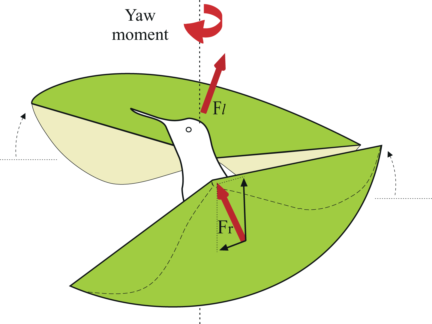
Schematic of flapping plane tilting.
Additionally, there is a couple of vehicles demonstrating hovering capability in which a tail is used to steer the robot. The most notable ones include DelFly 23,24 and Mentor. 25 These types of FWMAVs are not the topic of this article.
Our project, named Colibri (Figure 4) has evolved since 2012. Roshanbin et al. 10 demonstrated the controlled flight of our robot in pitch and roll motions was demonstrated. However, there was no control on yaw axis which is passively stable. The detailed design of its subsystems including the wing design, the wing drive mechanism, the pitch and roll control torques production, the avionics, and the proportional–derivative (PD) control is presented in the literature. 10,26 –28

General view of the Colibri robot demonstrating its main subsystems.
The previous work 10 showed that the pitch and roll torque productions are sufficiently decoupled to support the use of independent control loops for lateral and longitudinal motions. The primary challenge of wing-based yaw control mechanism is to avoid influencing on pitch and roll torques when a yaw torque is generated. This article focuses on the design and development of a novel control mechanism based on wing twist modulation technique to control the yaw motion while minimizing its influence on lateral and longitudinal motions.
The article is organized as follows: First, the torque generation principle of Colibri is explained and then the mechanical designs of two different architectures of series (Figure 7) and parallel (Figure 8) control mechanisms are introduced. The proposed architectures will be also analytically analyzed and the cross-coupling effects will be explored; additionally, the way how to overcome the unintended behavior will be addressed. Then, the control torque characteristics of the proposed mechanisms will be evaluated by measurement, and finally, the results of some flight experiments will be presented.
Control torque generation
The principles for controlling roll and pitch torques in the Colibri project were introduced by Roshanbin et al. 10 Here, we briefly review those principles and then explain the concept of yaw torque control based on wing twist implemented in Colibri.
Roll and pitch torques
The production of pitch and roll control moments is based on the modulation of the mean lift vector relative to the center of mass. To this end, the control bars are actuated to modify the camber distribution along the span (Figure 5). Modulating these bars produces a reorganization of the air flow which moves the center of pressure along the wing span. A dissymmetry between the left and the right wing will produce a roll moment by relocating the mean lift force sideways, and a dissymmetry between the front and the back half strokes will produce a pitch moment by relocating the mean lift force back or forth depending on its relative position to the center of mass. 10 Thus, the roll moment is achieved by moving the control bars sideways, and the pitch moment is achieved by moving the control bars equally back and forth, without significant influence on the magnitude of the lift force.
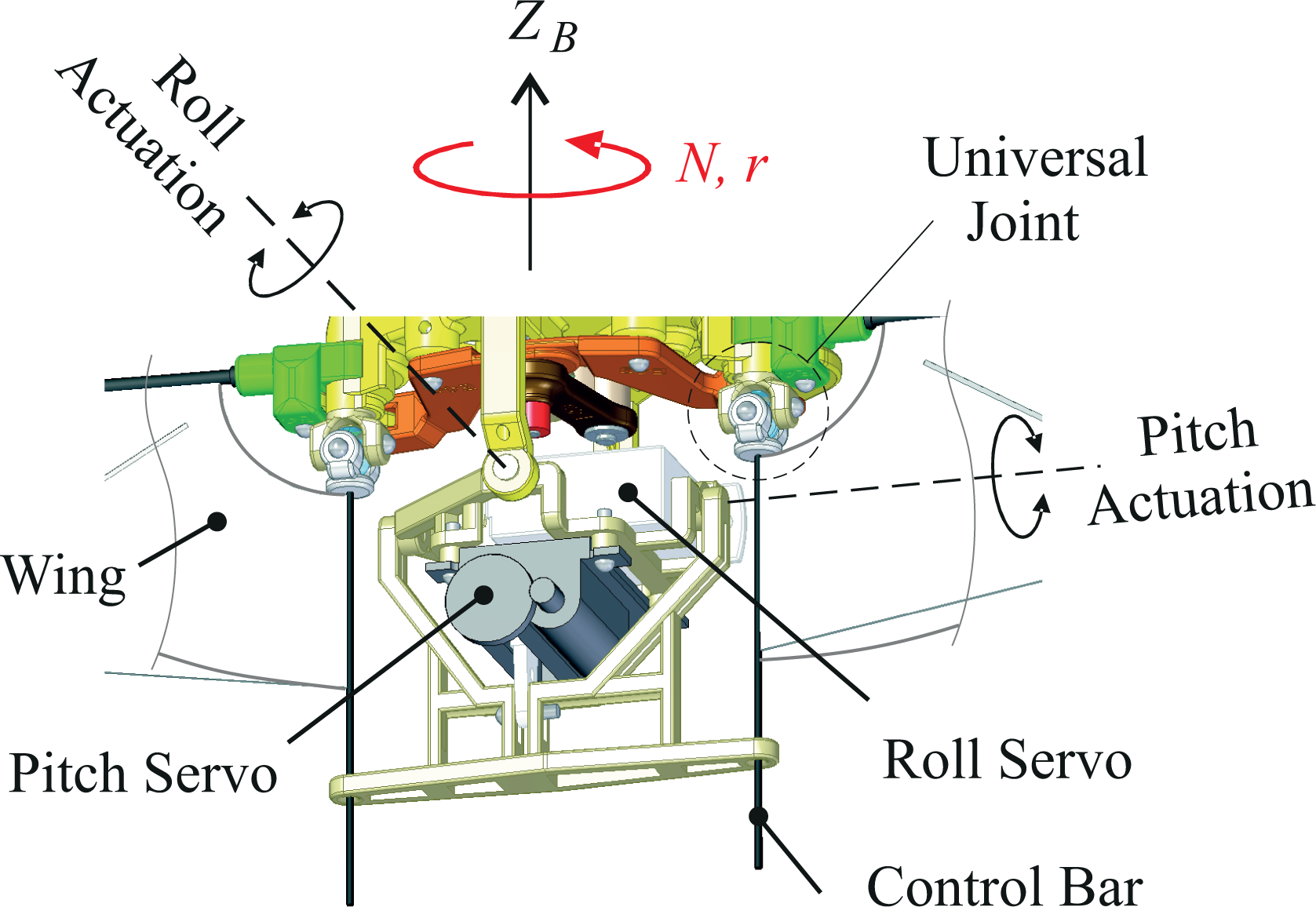
Wing twist modulation mechanism for pitch and roll control. A rotary servo is used for roll control and a linear servo mounted in series on the roll servo is used for pitch control. The pitch and roll axes intersect.
The pitch and roll axes are sufficiently decoupled to allow independent control loops for the axial (pitch) and lateral (roll) dynamics. Flight tests, however, revealed that flights stabilized in pitch and roll tend to spin about the yaw axis. The spin velocity, r, results from the equilibrium between a parasitic yaw torque and the rotational damping about the yaw axis. The parasitic yaw torque is generated by the various manufacturing tolerances in the 3-D printed parts of the robot; it is particularly sensitive to the differential tilting of the flapping planes of the two wings with respect to the pitch axis, exactly according to the principle described in Figure 3: a differential tilting of α (rad) generates a yaw torque of
Yaw torque
In contrast to the pitch and roll productions that are based on the lift vector modulation, the yaw moment mechanism in Colibri is controlled via differential drag produced by modulating the mean drag forces of the right and left wings using the mechanism known as wing twist modulation. In this design, the control bars are connected to the flapping frame through universal joints (Figure 5), and they are actuated in opposite directions to produce yaw torques. Consequently, the wings will experience different AOA during a wingbeat cycle if the yaw motion is commanded. This is different from what was mentioned in the introduction for wing rotation modulation 22 in which the AOA stays constant during the whole half wingbeat cycle. If the control bars are actuated counterclockwise (similar to Figure 2), the left wing will have a higher cycle-averaged drag coefficient on the upstroke, and the opposite wing will have a higher cycle-averaged drag coefficient on the downstroke. This creates an asymmetry in drag forces on each wing over the wingbeat cycle, resulting in a net yaw torque. An opposite torque is obtained if the control bars are actuated clockwise. This technique was first introduced by AeroVironment in Jupiter series of aircraft and later abandoned in favor of the wing rotation modulation, due to coupling effects. 9 This article addresses the cross-coupling effects of wing twist modulation and proposes solutions to tackle it.
Vehicle design
A general view of the Colibri robot is shown in Figure 3; the detailed design of the various subsystems is presented in the literature. 10,26,28
The flapping mechanism consists of two stages: a slider crank to produce the flapping motion and a four-bar linkage mechanism for motion amplification. The wings have a single degree of freedom (flapping) and the wing camber is obtained passively. The current version of the Colibri robot has a total mass of 24.8 g, a wing span of 21 cm, and a flapping frequency of 22.3 Hz.
Figure 6 illustrates the block diagram of the pitch/roll control system. An onboard flight control board combines the angular rates measured by a three-axis gyroscope with the tilt of the gravity vector estimated by a three-axis accelerometer to extract the pitch and roll Euler angles. A PD controller is implemented for stabilization purposes. The feedback states are pitch and roll attitudes and their Euler angles. The second-order Butterworth filter acts on the rate signal with a corner frequency of 10 Hz to filter out the flapping vibration. The gimbal system was used to adjust experimentally the control gains (more details can be found in the study by Roshanbin et al. 10 ).

Block diagram of the PD feedback control. PD: proportional–derivative.
The two control mechanisms presented here (series and parallel design) are equipped with three conventional micro servos for controlling the position of the wing root bars; one rotary for roll and two linear servos for pitch and yaw actuation. As explained in the next section, the coupling effect arising from the parallel design is small enough to be compensated by the feedback controller while in the series architecture a feedforward compensator is indispensable to maintain the robot stability.
Series architecture
The first yaw control mechanism implemented in Colibri was the one depicted in Figure 7. In this design, the pitch servo is mounted on the output of the roll servo and the yaw servo similarly is mounted on the output of the pitch servo. The yaw servo arm slides inside the slot of the control arm leading to a rotation of the control arm about the yaw axis. Therefore, a combined movement of pitch and yaw contains a radial component giving rise to unintended roll camber changes. This will be analyzed in the next section and a way to mitigate the coupling will be developed. However, it turns out that kinematic coupling cancellation by software is not effective in the whole actuation range, especially at the extreme range of the yaw actuation. This motivated the development of the parallel architecture described below.

3-DOF series architecture of control mechanism. 3-DOF: three-degree-of-freedom.
Parallel architecture
Figure 8 shows a control mechanism with two linear servos mounted in parallel at the output of the roll actuation. The two linear actuators control simultaneously the pitch and the yaw axes. In this design, the radial component of the yaw actuation observed in the series architecture disappears due to the linear movement of the control bars relative to roll actuation; the control bars can be moved independently to produce both pitch (by moving both servos together) and yaw torques (by moving the servos in opposing directions).

3-DOF parallel control mechanism. 3-DOF: three-degree-of-freedom.
Cross-coupling effects
While the pitch and roll torques have been found to be nearly decoupled, 10 the control characteristic measurements showed a pitch/yaw to roll coupling: an undesired roll torque will appear if a combined pitch and yaw input is needed. Two types of cross-coupling effects have been identified: a kinematic coupling in the series architecture and an aerodynamic one in both architectures. We will examine them successively below. The aerodynamic coupling is small enough to be compensated by the feedback controller, while the kinematic coupling arising from the series architecture makes the robot unstable if it is not compensated by a feedforward controller. The results of the coupling measurements and their amplitude comparison for both cases are presented in the “Torque characteristics evaluation” section.
Kinematic coupling (series architecture)
To investigate the cross-coupling effects, the kinematics of the series architecture is analyzed in the presence of both pitch and yaw inputs (Figure 9). The axes of the fixed coordinate system attached to the flapping frame is denoted as XYZ and the axes of rotated frame attached to the control arm as xyz. The origin of XYZ is located at the intersection of the rotation axes of the roll and pitch control mechanisms. Before rotation, the two coordinate systems coincide as depicted in the figure. We also define two intermediate coordinate systems of

Coordinate systems for the control mechanism in series architecture. XYZ is the fixed coordinate system attached to the frame and xyz is the rotated coordinate system which is fixed to the control arm. ϕ (roll) represents a rotation around the X axis, θ (pitch) is a rotation around
The vector

where

and

with the classical notations c for cos and s for sin.
After substituting equations (2) and (3) into (1), the vector
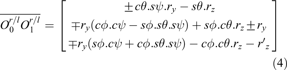
[recall that the top and bottom (plus or minus) signs in the equations refer to the right and left bars, respectively]. From this equation, the control bar angles responsible to generate roll moments can be obtained
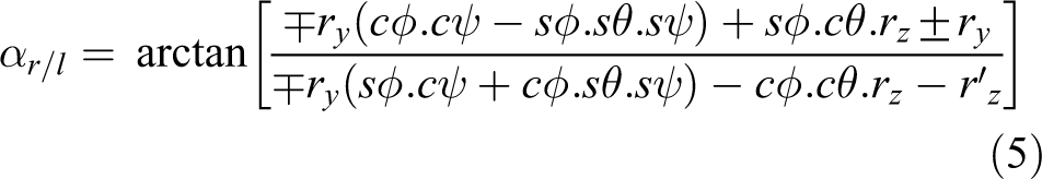
To cancel the roll torque, the roll angles of the right and left bars should be equal and opposite. Thus, the zero roll torque surface is the solution of
Therefore, the solution of the following equation determines a surface in which no roll is generated

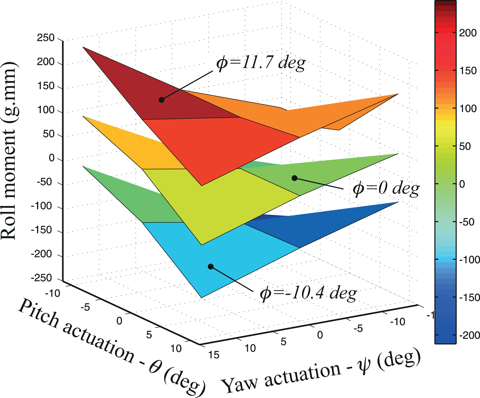
The equation is solved numerically in MATLAB (MATLAB 2015b [version 8.6]). Its solution is represented in Figure 10 for different pitch and yaw actuation angles.

Zero roll torque surface for different pitch and yaw actuation angles.
The roll moment values in the vertical axis of this graph are the torques required to cancel the cross-coupling effects. In extreme cases, it reaches up to 25% of the roll torque budget available to control the roll motion. The torque axis in the graph is a transformation of the actuation angles to the corresponding roll torque using the mapping shown in Figure 11. In this mapping, the angle of actuation is captured by a camera and the corresponding moment is measured by a six-axis load cell (Nano 17-E transducer, ATI Industrial Automation Inc.). Presenting the vertical axis by torque rather than angle will help us to compare the analytical results of this section with the moment characteristics measured experimentally in the next section.
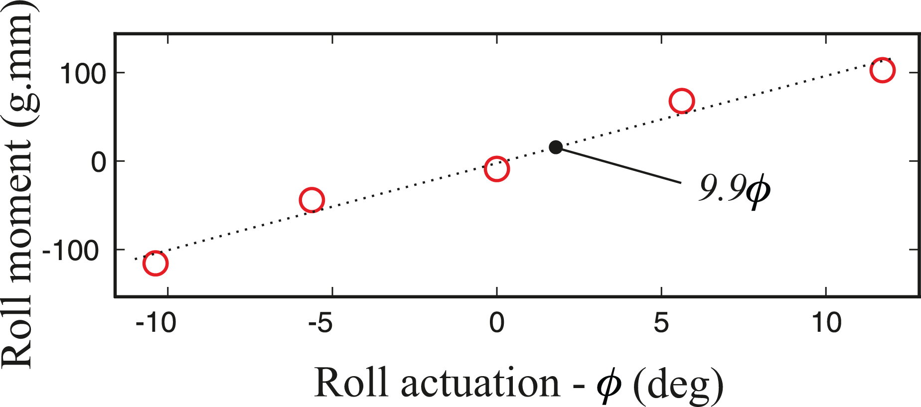
Roll moment as a function of roll actuation. The experiment is done with a flapping frequency of 20 Hz.
To correct the coupling effects, equation (6) has to be simplified to be implemented in the control board. Thus, the kinematic coupling term is approximated by a hyperbolic paraboloid surface.

in which coefficient
To conclude this section, the undesired roll torque produced by the kinematic coupling of a combined pitch and yaw input of the series architecture can be ideally corrected by a feedforward command if the roll servo moves along the hyperbolic paraboloid surface described by equation (7).
Lift variation coupling (both architectures)
In the parallel architecture of the control mechanism implemented in Colibri, the yaw torque is achieved by introducing different inputs to the two linear actuators also responsible for the pitch input; it is not subject to the kinematic coupling discussed above and it demonstrated some stable and successful flights. However, the flight tests showed that the lateral motion is affected when a yaw command is applied. To quantify this problem, the lift production of wings is measured as a function of the pitch command (Figure 12). The result shows that the lift force slightly decreases when the control bars are deviated from their vertical position. Consequently, if the control bars are commanded differently in presence of the pitch command, the differential lift of right and left wings induces some roll coupling. This lift variation coupling can be estimated as follows


Top: schematic view of the robot demonstrating unintended roll generation as a result of differential lifts. Bottom: lift production of a single wing as a function of pitch command. The flapping frequency is 20 Hz.
where
The lift to pitch servo command curve of Figure 12 can be well approximated by a second-order equation

and the linear servos position


Coordinate system for the control mechanism in parallel architecture.
In which θ and ψ denote pitch and yaw actuation angles. If we substitute equations (9) and (10) into equation (8), the coupling can be written as

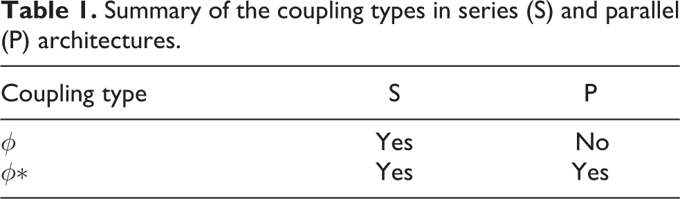
It is an interesting result since both kinematic coupling (ϕ) and lift variation coupling terms (ϕ*) have the same shape. Moreover, since the lift force curve is not also flat in the series architecture, its coupling will be the summation of both equations (7) and (11). Table 1 summarizes the cross-coupling types in both architectures.
Summary of the coupling types in series (S) and parallel (P) architectures.
As the result of the control torque measurement of the next section shows, the roll coupling resulting from the lift variation is small enough to be compensated by the feedback controller (
Torque characteristics evaluation
To assess the torque characteristics of the control mechanisms with respect to cross-coupling, a six-axis load cell (Nano 17-E Transducer, ATI) is used for torque measurement. The moment resolution of the sensor is 1.56 g·mm, and force resolution is 0.31 g. The tested prototype is mounted upside down vertically on top of the sensor in such a way that the z axis of the sensor passes through the center of mass of the robot (Figure 14). The coordinate systems

Setup for measurement of the control moments showing the coordinate systems of the transducer and the tested prototype. The prototype is mounted upside down on the transducer.
where

The following subsections present the results of the torque production of the tested prototype for both architectures based on the method explained here. In all experiments the flapping frequency is approximately 20 Hz, and the time-averaged torques and forces over a period of 3 s are reported as the torques and forces generated at each control input.
Series architecture
Two different sets of experiments with and without implementing the cross-coupling correction term have been conducted. In both experiments, the mechanism is evaluated at all possible combinations of the control input actuation angles indicated in Table 2. These positions are the extremes and the middle position of the control mechanism in roll, pitch, and yaw axes. Figure 15 shows the results of the first set of experiments when the correction of the coupling term is not implemented. The experiment shows the same shape as equations (7) and (11), that is, a hyperbolic paraboloid surface. Also parallel surfaces indicate the same coupling behavior at different roll actuation angles.
Control input actuation angles used for series architecture evaluation.

Roll torque at different combination of pitch (θ), roll (ϕ), and yaw (ψ) input for series architecture. The coupling term correction is not implemented.
The first row of Figure 16 shows 2-D cross sections of Figure 15. One sees that, for zero actuation angles of pitch and yaw, some roll coupling torque is measured, due to manufacturing uncertainties and misalignments; the measured roll torque diagram is shifted with respect to the zero actuation angles in pitch and roll (

2-D cross sections of roll torque at different combination of pitch, roll and yaw input for the series architecture. Row (a): the coupling term correction is not implemented, row (b): the coupling term correction is implemented.

The second row of Figure 16 shows the 2-D results of the roll torque when this correction term is implemented. Although a substantial improvement of the control characteristics with respect to the cross-coupling of the mechanism is observed, the coupling remains important near the limits of the yaw command, leading to some divergent flights.
Parallel architecture
The same procedure is followed for evaluating the parallel architecture of control mechanism. However, since in this mechanism the range of the actuation angles for pitch and yaw is narrower than in the series design, the pitch actuation angle was altered from –4° to 4°, and the yaw actuation angle was changed from −7.2° to 7.2 deg. The roll actuation angles are those given in Table 2. The result of the experiments (Figure 17) shows the consistency of its shape with what equation (11) suggests. Moreover, Figure 3 shows that the roll coupling due to lift variations is no more than 15% of the roll actuation amplitude that is less than the coupling observed with the series architecture when the correction term is implemented (Row B of Figure 16).
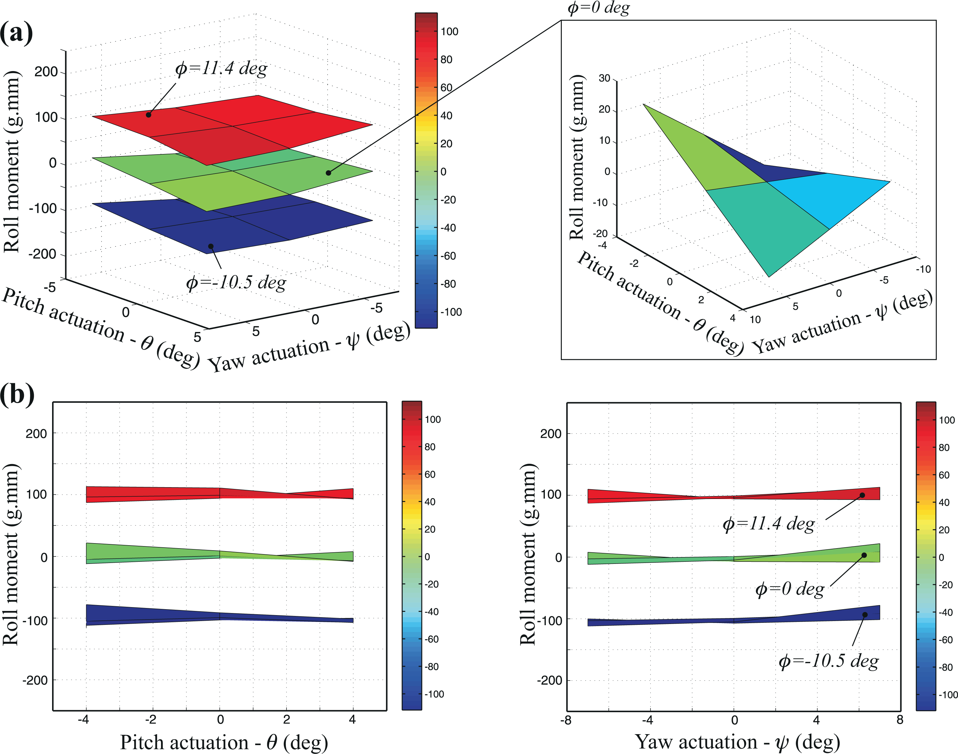
Roll torque at different combination of pitch, roll and yaw input for parallel architecture. Row (a) and (b) are 3-D and 2-D illustrations, respectively.
Flight experiment
Flight experiments are performed in a flight room equipped with eight OptiTrack Flex 13 motion tracking cameras. The room provides position and orientation of the robot at the rate of 120 frames per second (fps) by tracking the position of three retroreflective markers attached to the robot (Figure 18) . The same flapping wing robot used for characterizing the moments was utilized for free flight experiments. A PD controller is implemented for pitch and roll to stabilize the robot and the control gains are the ones presented by Roshanbin et al. 10 Two different sets of flight tests have been conducted to evaluate the series and parallel architectures of the control mechanism. In the first experiment, the robot is equipped with a series architecture of the control mechanism, and it flies for about 1 s with zero yaw command, then, it is commanded in yaw direction by 77% of its maximum amplitude (Figure 19); the flapping wing robot is stable in pitch and roll when the yaw command is applied. This shows that the coupling effects are reduced enough by the method presented in the text and thus adding the yaw command is not detrimental to the flight stability (pitch and roll values are less than 10°). Also, this figure shows that adding the yaw command effectively changes the heading rate of the robot from −33° s−1 to −248° s−1.

The tested prototype equipped with three retroreflective markers.

Robot attitude for series architecture when the yaw command is changed from
Figures 20 to 22 show the second sets of flight tests in which the parallel architecture of control mechanism is utilized. These three experiments are performed with the yaw command of 7.5°, −7°, and −10° (the video is available as a Online Supplemental Material). From the results, the following conclusions can be drawn:
The remaining cross-coupling (ϕ*) caused by this control mechanism is small enough to allow the robot to be stable without adding the correction term.
Utilizing two linear servos in parallel with possibly slightly different dynamics is not detrimental to the pitch stability.

Robot attitude for parallel architecture when yaw actuation angle is 7.5°. The heading rate is 156° s−1.
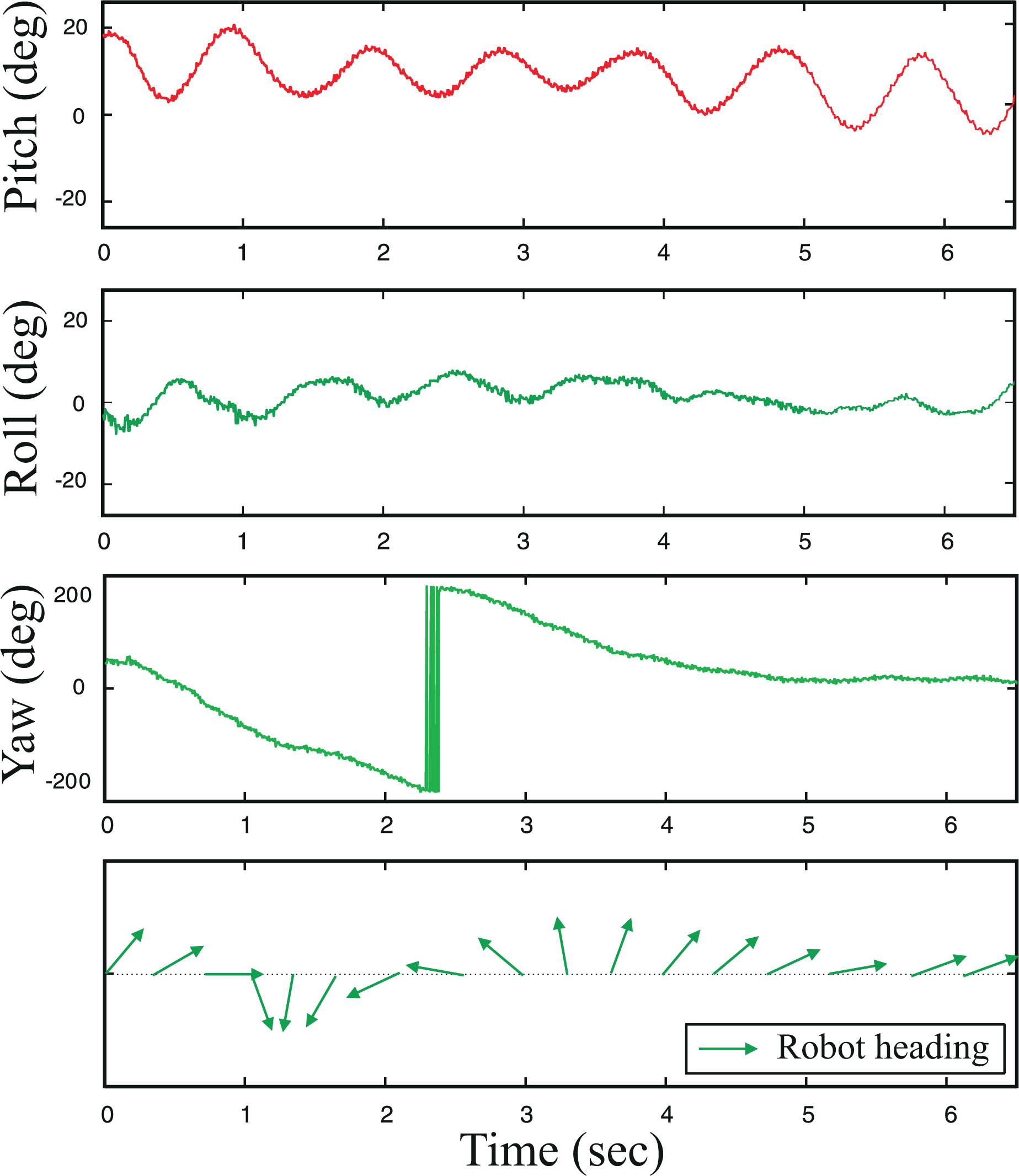
Robot attitude for parallel architecture when yaw actuation angle is −10°. The heading rate is −100° s−1.

Robot attitude for parallel architecture when yaw actuation angle is −7°. The heading is nearly constant.
The results demonstrate the ability of the proposed control mechanism to change the robot heading rate from −100° s−1 to 156° s−1 by yaw command manipulation.
The 3-D trajectory and the composite image of the second flight of the parallel mechanism with the yaw command of −7° are also presented in Figure 23. Due to inevitable manufacturing and assembly asymmetries, this yaw command for the tested prototype is needed to keep its yaw heading direction nearly constant.

Top: composite image of the flight test with yaw actuation of −7°. Bottom: the corresponding 3-D plot of its trajectory.
Conclusion
The goal of this work has been to develop a tailless hovering flapping wing robot capable of generating the yaw torque in addition to the pitch and roll torque. The primary challenge of the wing-based yaw control approach was to generate the yaw moment with minimal influence on lateral and longitudinal motions. Two control mechanism architectures have been considered to modify the wing kinematics by moving the control bars, a series architecture where the yaw control servo is mounted on the output of the pitch servo and a parallel one where two linear servos control simultaneously the pitch and yaw axes. In both mechanisms, the yaw torque is manipulated by differential drag produced between the right and the left wings. This differential drag is achieved by actuating the control bars in opposite directions.
The kinematics of both designs were mathematically analyzed and the results were verified by the torque characteristics evaluation using a six-axis load cell (Nano 17-E Transducer, ATI). The results showed that the series architecture is responsible for a kinematic coupling between control axes, which generates unintended roll torque when both yaw and pitch control torques are requested. The analytical investigation demonstrated that the kinematic coupling behaviour can be well approximated by a hyperboloid surface. Accordingly, this surface was used as a coupling estimator to correct the unintended roll production. Although the control torque measurements showed that this cross-coupling torque can be alleviated to a large extent by a feedforward control, it still remains important near the limits of the yaw command. This, in fact, motivated the development of the parallel design as a mechanical solution to mitigate the cross-coupling involved. The mathematical analysis of the parallel architecture showed that it does not lead to any kinematic coupling and has been found preferable. For both architectures, some aerodynamic coupling occurs as a result of the slight dependency of the lift on the pitch command; however, experiments showed that the roll coupling resulting from the lift variation never exceeds 15% of the actuation amplitude and can be handled by the feedback controller without threat to the flight stability.
The efficacy of the two architectures was also assessed by performing several flight tests. The flight experiments of the robot equipped with the series design showed that the kinematic coupling was sufficiently diminished by implementing the feedforward compensator to allow the robot to remain stable. Although successful, the robot with this mechanism would diverge in some cases, specifically at the extreme range of the yaw actuations. However, the flight experiments of the robot equipped with parallel control mechanism confirmed that the Colibri could successfully change its heading rate while remaining stable without implementing any corrections by software.
In spite of the careful design of the flapping wing propulsion system for flight autonomy enhancement, 28 demonstrating a longer flight for exploring the closed-loop yaw motion was not feasible at this stage. Increased flight endurance may be accomplished either by reducing the weight of the robot (e.g. using light-weight carbon/epoxy panels for robot structure) or by further efficiency enhancement of the propulsion system. This is the topic of the future work.
Footnotes
Acknowledgements
The authors wish to thank Joachim BUI for his contribution to the CAD model designs of the yaw control mechanisms.
Declaration of conflicting interests
The author(s) declared no potential conflicts of interest with respect to the research, authorship, and/or publication of this article.
Funding
The author(s) received no financial support for the research, authorship, and/or publication of this article.
Supplemental material
Supplemental material for this article is available online.
References
Supplementary Material
Please find the following supplemental material available below.
For Open Access articles published under a Creative Commons License, all supplemental material carries the same license as the article it is associated with.
For non-Open Access articles published, all supplemental material carries a non-exclusive license, and permission requests for re-use of supplemental material or any part of supplemental material shall be sent directly to the copyright owner as specified in the copyright notice associated with the article.