
Abstract
For the future demands of unmanned assembly of orbital space truss structures, a new space truss-crawling robot based on biomimetic principles is proposed. The robot system mainly consists of multi-joint legs and an adhesive microstructure imitating a gecko. The kinematics analysis of a single leg and the system design are accomplished based on functional requirements and adaptivity analysis. The motion simulation model of the robot and the discrete element simulation model of the adhesion microstructure are established based upon this analysis. The simulation of the holding motion of a single leg is implemented based on the EDEM-ADAMS platform, and the feasibility of the scheme is demonstrated by analyzing the influence of adhesive microstructures comparatively. The related motion characteristics of the robot while crawling are obtained by co-simulation, and the influence law analysis is carried out by analyzing the interaction between not only the crawling infrastructure but also the crawling gait and motion characteristics. A crawling experiment in a simulated low-gravity environment is conducted to further verify the robot’s movement function, which will provide beneficial reference for practical applications of the robot in the future.
Introduction
With the rapid development of space technology, the structure and function of spacecraft and other spatial mechanisms with the truss as their basic structure have become larger and more complex. Constrained by design and launch costs, the limitations of traditional ground manufacturing integration methods have become increasingly evident. In contrast, space crawling robots have the advantages of high flexibility, a large workspace, and low cost. Applying this technology to the field of orbital truss assembly, not only the operating range of space manipulators can be expanded, but also astronauts can be spared from performing these off-board missions, reducing their risk. 1,2 The technology has important research value and broad application prospects.
Crawling robots are an important branch in the field of robotic. Many countries in the world have conducted in-depth research on crawling robot technology, including scheme planning and prototype manufacturing, and have achieved some results. Figure 1(a) and (b) shows robot systems in space environment, 3,4 while Figure 1(c) and (d) is crawling robots in a conventional ground environment. 5 –7 Their crawling principles and locomotions are different, but they are all able to climb specific infrastructures, such as trusses, walls, and poles.

Crawling robots. (a) Skyworker. (b) SpiderFab Bot. (c) Abigaille-III. (d) RISE V3.
In addition, animals in nature can provide a basis for the design of robots from the biomimetic perspective. Their body structure and movement mechanisms are the result of long processes of evolution and have excellent environmental adaptability. 8,9 Similarly, the aim of creating crawling robots is to replace humans with the ability to execute multiple tasks in a wider range of environments. Therefore, taking reptiles as biological archetype and combing modern biomimetic technology can create a foundation for the research of truss-crawling robots.
A new type of crawling robot adapted for truss infrastructures is proposed. The robot system has a six-legged symmetrical structure and can adapt to different types of truss structures. To provide basic locomotion, an adhesive microstructure, called biomimetic setae, imitating those on gecko’s feet is added to the inside of the robot’s legs. Combined with the mechanical clamping of the legs, the adhesion effect of the biomimetic setae improves the stability of the robot during operation. The structure and motion characteristics of this robot need to be further studied.
Design of robot system
The completion of the orbital truss assembly requires the robot to not only crawl stably on the truss but also to climb under different working conditions, which require greater adaptability of the robot’s movement function. By analyzing the diversity of crawling infrastructures, we identify three situations the robot may encounter, including large-section truss rods, large-scale truss structures, and spacecraft surfaces. The following structural design is carried out based on the infrastructure analysis.
Mechanical design
Legs, used to grasp the infrastructure, are the most important structure in the crawling robot. The crawling ability of insects in the order Phasmatodea (walking sticks) is very flexible in nature. After studying its body configuration and locomotion, we choose to use rotating joints in the legs of the robot. The overall structure of the robot is symmetric, and the six legs are evenly distributed on both sides of its body. However, the 3 R structure of legs is not applicable because of the structural features of the space truss. Especially when the robot is crawling on a truss rod, the completion of the leg’s movement depends on the rotation of each joint. But the legs have a certain width, which makes the edge of the leg and the outer circle of the truss rod tangent, which would result in point contact if not deformation. A 3 R structure cannot provide effective clamping force and can even result in instability. Therefore, adding a rotating joint to the legs can improve contact between the leg and the infrastructure, as shown in Figure 2.

The benefit of adding a rotating joint.
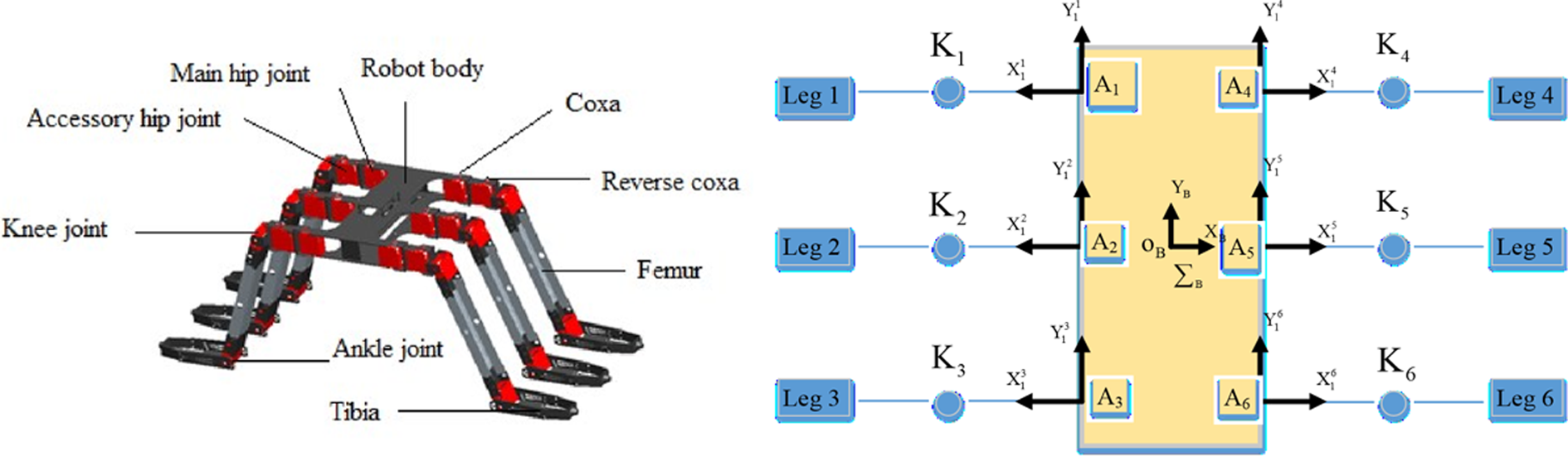
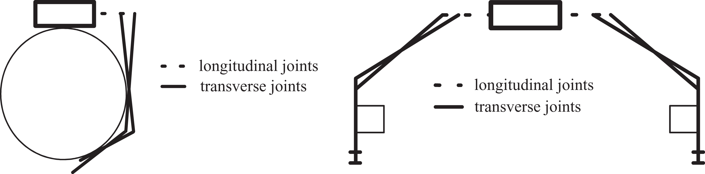
Based on the above analysis, a multi-joint leg configuration was selected, each leg having four rotational degrees of freedom: the main hip joint, the accessory hip joint, the knee joint, and the ankle joint. The rotation axis of both the hip joints is designed to be perpendicular to the robot body, therefore, called longitudinal joints, and the rotation axis of the knee joint and the ankle joint is designed to be parallel to the robot body, therefore, called transverse joints. These four segments, referred to as coxa, reverse coxa, femur, and tibia, are connected to the body by the four joints. A three-dimensional model of the robot is shown in Figure 3.
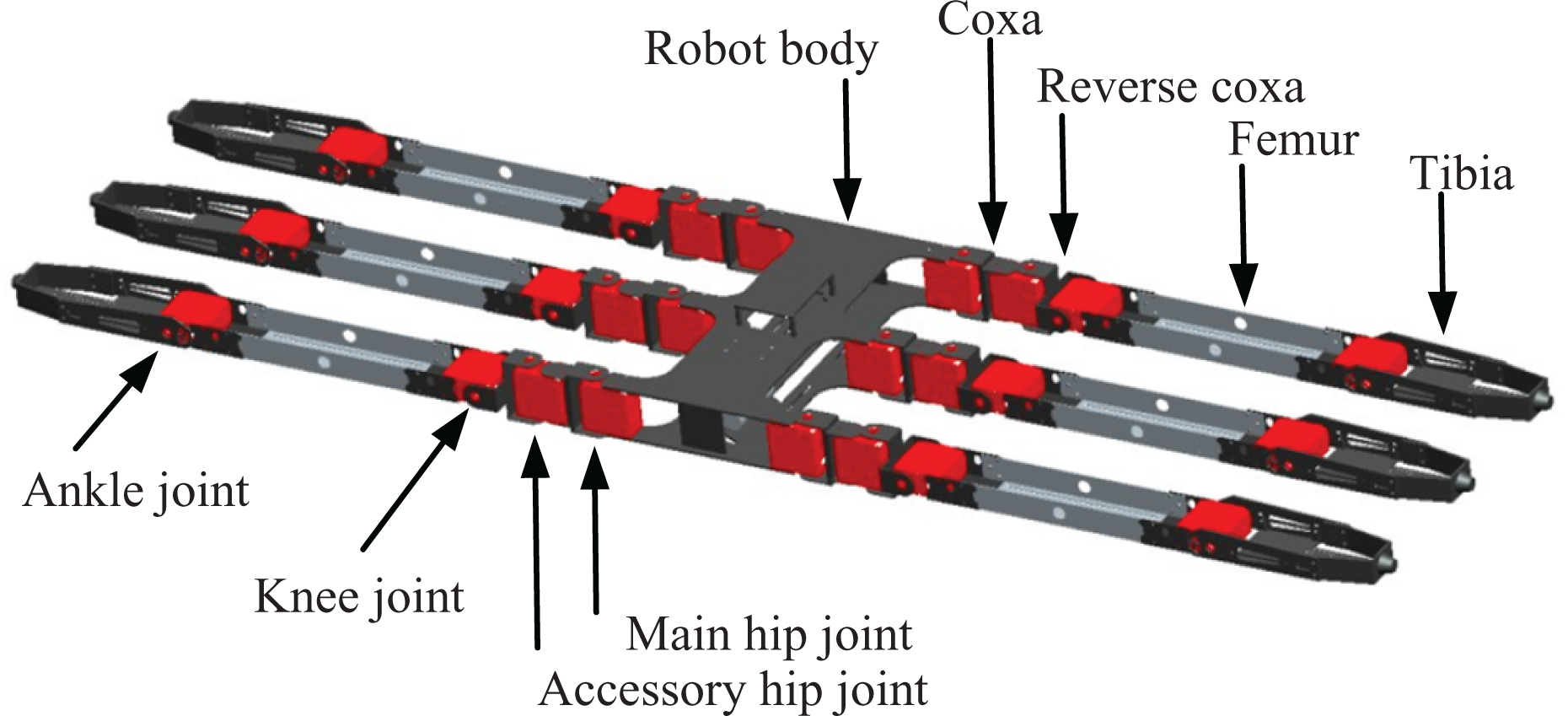
Three-dimensional model of the robot.
Design of the adhesive microstructure
Because of the special space environment, both vacuum and microgravity affect the robot. The chosen structural design meets the requirements for the infrastructure adaptability of the robot, but at the same time, it ensures that both the inside of the robot’s legs and the outside surface of the rod are in rigid contact with each other. However, it is impossible to maintain uniform and complete contact, which will lead to decreased stability while crawling, and the grip may loosen, affecting the effectiveness of the robot during space missions. Here, the achievements of gecko robots can be leveraged. This hexapod robot, therefore, adopts the gecko’s gripping mechanism, 10 –14 which employs an adhesive microstructure on the inner surface of the robot’s legs. Its structure and adhesion mechanism are shown in Figure 4.

Adhesion mechanism of gecko robot.
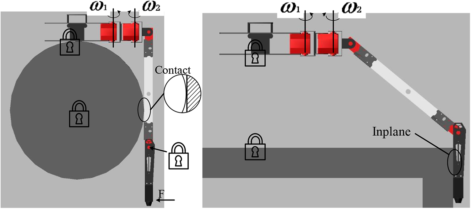
After gripping the infrastructure and achieving geometric locking, traction is further improved due to the increased flexible contact coming from the adhesion of the biomimetic setae microstructure. As a result, the crawling process and the orbital operation of the robot become more stable. Additionally, the robot’s configuration can also transform by reversing the tibia, as shown in Figure 5. This places the inner surface of the tibia in contact with the infrastructure, thus the setae located there allow the robot to grip a planar surface. In the absence of gravity, if the van der Waals adhesion force due to the contact is enough to overcome the inertial force of the robot itself, the robot can move forward.
Reversed tibia for operation on planar surfaces.
Analysis of motion function
For grasping space truss infrastructure, the crawling process of the robot is decomposed into the gripping of a single leg and the crawling process of the whole machine, then the motion function is further analyzed.
(1) The gripping movement of a single leg.
The movement of the crawling robot can be simply broken into lifting, dropping, adhesion, desorption, and lifting of each leg before repeating. Thus, the gripping motion of a single leg is the first basic movement function. The truss rod can have a rectangular or circular cross section; when crawling, if the cross section is rectangular, the legs and rods are in parallel contact with each other, relying on symmetrical mechanical clamping force and the biomimetic setae sticking to the truss rods for grip. If the cross section is circular, the legs and rods will be in tangential contact with each other, at which point the setae’ adhesion will play a major role, as their flexible contact is combined with the relatively small line contact, as seen in Figure 6. (2) The crawling process of the whole machine.

Contact situation for different infrastructures. (a) Large-scale truss structure and (b) large-section truss rods.
While crawling, the state of each leg is either “swinging” or “supporting.” When the setae of a leg complete desorption and lift up, the hip joint rotates to drive the body forward and the leg is “swinging.” When the setae of a leg remain adhered to the truss, the body moves along with the rotation of the hip joint, and the leg is “supporting.” The six legs of the robot are divided into two groups, repeatedly transitioning from swinging to supporting, so the robot is able to crawl forward continuously. It should be noted that when a supporting leg drives the body to move, the femur and tibia need to be adjusted in real time. This is because each joint is revolute yet the length of the leg is invariable. As the robot’s body moves, the distance between the longitudinal joints and the body will first increase and then decrease due to the reverse movement of these two joints. To ensure the stability of the supporting legs, the contact angle between legs and truss rods needs to be adjusted with respect to the femur and tibia’s rotation. When the rotation angle of the leg’s hip joint reaches its maximum, the lateral displacement of the lateral joint also reaches its maximum. Similarly, when the crawling infrastructure is a large-scale truss, the femur and tibia of the robot also need to adjust their contact angles in real time for the same reason, to ensure good contact, so the robot can move forward steadily. The difference is that the tibia of the legs is in parallel contact with the truss structure and they are in a state of relative movement in the longitudinal direction during the adjustment process. The specific situation is shown in Figure 7.
Schematic of changes in transverse joint angles of supporting legs during robot body motion.
Kinematic analysis of a single leg
The kinematic analysis of a single leg is primarily concerned with interference with the adjacent leg during the crawling process and the movement sequence. The positive and inverse kinematics analysis results are also applied to the gait planning of the robot to provide a basis for the subsequent simulation.
The single-leg configuration of the robot is shown in Figure 8. First, the hip joint is used as the base joint and the base coordinate system of the body is set to coincide with it to establish the kinematic model. The traditional D-H modeling method requires simple correction, including the following two aspects: first, the Xi-axis points in the direction of Zi to

The D-H coordinate system for a single leg.
The homogeneous transformation matrix of adjacent coordinate systems is

Where θi is the angle of rotation of the ith joint; αi is the twist angle of the axis between the ith joint and its adjacent joint; ai is the length of the leg driven by the ith joint; and di is the distance between the ith joint and its adjacent vertical line.
The coordinate parameters of the hexapod robot are shown in Table 1.
Coordinate parameters for the D-H model.

Substituting the parameters in the table into the matrix and consecutively transforming the homogeneous transformation matrices of adjacent joints, the transformation matrix of the robot’s single-leg foot coordinate system relative to the leg-base coordinate system can be obtained

In equation (2), the matrix R is the rotation matrix of the robot’s foot-end coordinate system, which indicates the attitude of the end. Because there is no corresponding actuator at the foot, no detailed analysis is performed.

Spatial analysis of a single leg.
The application of inverse kinematics is mainly to solve the real-time change of the joint angle at the contact between the supporting leg and the truss while crawling. We directly use ADAMS [version 2013] software to solve the inverse kinematics of a single leg to avoid the disadvantages of large calculation volume and limited geometric conditions. When setting up the drive, combined with kinematic analysis results, the driving functions of the main hip joint and the accessory hip joints are defined by the cosine curve as given by the desired step length and pace. The cosine curve is used as the basis to ensure that the rotational speed of the two longitudinal joints is relatively flat, and there is no abrupt change in joint acceleration, thereby reducing the impact on the legs when they are lifted, which helps to improve the stability of the robot when crawling. At the same time, a constant force is specified at the foot of the robot, which is used as an external input to limit femur and tibia passive rotation according to the set contact state, as shown in Figure 10.
Inverse kinematics analysis in ADAMS.
In the extracted speed–time curve of the joints, taking the knee joint as an example, the intercepted curve segment of the attitude adjustment process when the femur of the supporting leg contacts the truss structure is the desired inverse solution, as shown in Figure 11. The inverse solution of other joint contact angles is similar to this.

Reversal curve of the knee joint.
The intercepted curve is used as an active input for joint motion, establishes the follow-up robot motion control simulation model, and will be edited again in the order of the robot motion.
Modeling and simulation
In actual conditions, the setae are densely distributed and have a large deformation when compressed. It is difficult to observe the deformation of a large number of setae during the actual movement of the legs using the finite element method, and the variable-force contact state during the attitude adjustment of the leg cannot be accurately described. But from the perspective of the discrete element, the single setae can be modeled as a cylinder composed of multiple particles. The interaction force between the particles can restore the flexibility and toughness of the setae, making the simulation model more representative of the actual condition. We chose the discrete element software EDEM to model the biomimetic setae on the legs of the hexapod robot. 15 However, the relationships of the complex motion between multiple geometries can’t be built in EDEM, so the simulation model of the robot’s crawling motion needs to be built in ADAMS, and they are conducted as a co-simulation.
Simulation model
As a flexible body, the adhered microstructure will deform upon contact with the infrastructure. The Hertz–Mindlin with bonding model is selected as the contact model for the component particles of the setae. A large number of particles constitute the setae through bonding and are able to withstand tangential and normal forces. The bonding between particles relies on similar cylinders, like a chemical bond. The small deformation caused by the force of the plurality of particles can form a large deformation of the entire setae. In addition, the setae are arranged in a matrix pattern, distributed on the inside of each leg of the robot. So the application programming interface (API) method is used to control fixed-point generation of particles. The JKR model is used to characterize the adhesion between the setae and the surface of the object. 16 The adhesion energy between the particles and the geometry is set to w = 0.1 J/m2 to ensure that the dense setae array will not stick to each other. The model of the setae of the robot’s leg is shown in Figure 12. The adhesive microstructure on all six legs follows the same method.
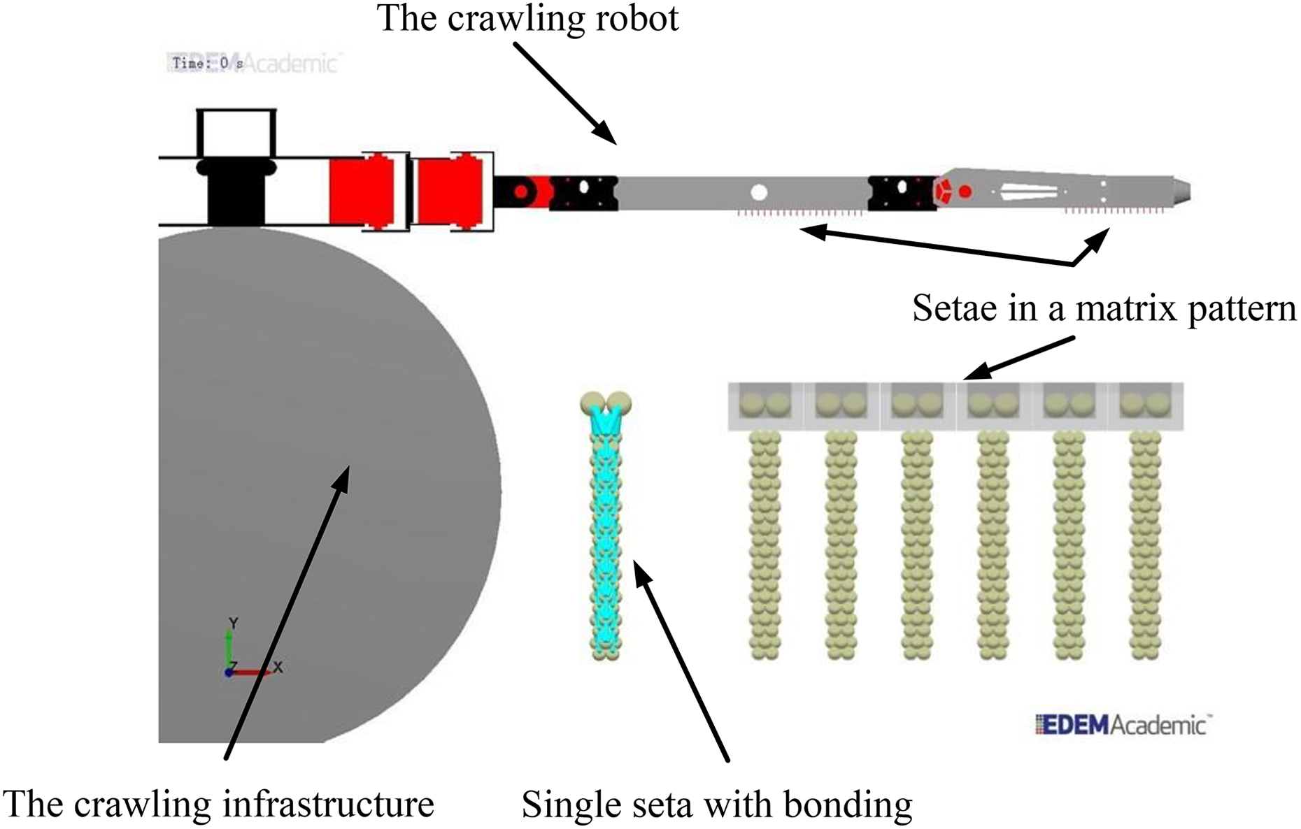
Model of biomimetic setae on robot’s leg.
The positive kinematics analysis results are used to plan the driving curve of active striding for each joint and the inverse kinematics results are used to plan the driving curve when the joint is passively adjusting the robot’s posture. The two types of motion simulation models of the established robot crawling on large-section truss rods and large-scale truss structures are shown in Figure 13.

Two kinds of robot motion simulation models.
We use the EALink plug-in as a co-simulation interface to connect the models in EDEM and ADAMS. However, there are a large number of robot components; thus, in EDEM, the crawling speed, displacement, and force of the legs are mainly studied. Therefore, it is sufficient to set part of the components to be included in the coupling, including the robot body, truss, and legs. This will simplify the model and increase the simulation speed without affecting the simulation results.
Co-simulation based on EDEM-–ADAMS platform
While crawling, the robot’s movement is not only affected by its own structure but also the infrastructure and crawling gait. 17 –20 The co-simulation of the robot crawling also addresses these two factors. Both the typical triangular gait and the creeping gait derived from it are designed to move the six legs in two groups, as shown in Figures 14 and 15. L1, L3, and R2 are in one group, and L2, R1, and R3 are in another group. The difference between the two gaits is in the sequence of movement of the two sets of legs. This causes a corresponding difference in the characteristics of the two gait movements.

Schematic of crawling in triangle gait.

Schematic of crawling in creeping gait.
The co-simulation of the robot crawling is based on the above models. After cross-combination of two crawling infrastructures and two crawling gaits, there are four simulation schemes. The co-simulation process of the overall crawling of the robot using a triangular gait with the large-section truss rod as the infrastructure is shown in Figure 16. The simulation model in ADAMS is on the left and the model in EDEM is on the right. Because there is one more gripping process during crawling, the simulation time for a creeping gait is 0.5 s longer than for the triangular gait. The simulation process using large-scale truss infrastructure is similar, and not given in detail.

The co-simulation process of the overall crawling of the robot using the triangular gait with the large-section truss rod infrastructure. (a) 0-s initial posture of the hexapod robot. (b) 0.5-s gripping action is completed. (c) 1 s first group of legs move half a step. (d) 1.5 s the body moves forward one step, while the second group of legs move half a step. (e) 2 s the body moves forward one step, while the first group of legs move one step. (f) 2.5 s the body moves forward one step, while the second group of legs move one step. (g) 3 s repeat this process and continue to crawl.
The simulation shows that the adhesive microstructure inside the leg of the robot successfully adheres to the truss rod, and the body moves forward relying on the force generated by the rotation of the hip joint. During the entire crawling process, the movement of the robot is accompanied by changes in the force of the legs. The simulation results are extracted to obtain a curve of the tangential adhesion force over time, as shown in Figure 17. In the curve, only the change of adhesion force during the real-time contact between the supporting leg and the rod is relevant, that is, the curve segment from negative to positive after 1 s, which is the main source of force change in the leg.

The curves of the tangential adhesion force of the robot’s leg over time. (a) Large-section truss rod, triangular gait. (b) Large-section truss rod, creeping gait. (c) Large-scale truss structure, triangular gait. (d) Large-scale truss structure, creeping gait.
The driving force of the robot comes from the adhesion force provided by the adhesive microstructure. Therefore, the stability of the robot’s movement is directly related to the change in adhesion force. The fluctuation range of the tangential adhesion force in four cases is shown in Table 2.
Fluctuation range of tangential adhesion forces.

We can see from the simulation that the robot can complete the crawling movement, no matter what type of gait and infrastructure, that is, the adhesion meets the robot’s needs. The difference is that the force of the leg is not constant, and there is a fluctuation range of the adhesion force. A small or large range in that force corresponds to good or bad stability of the robot, respectively. The more uniform and more constant the adhesion force of the leg is, at the microscopic angle, the more ideal the contact condition between the inner setae of the leg and the crawling infrastructure is. This means that the better the overall crawling effect of the robot is, the greater the carrying capacity is. According to the range of adhesion fluctuations, the lengths of the fluctuation intervals are calculated under four conditions


We can see that the length of the adhesion force fluctuation range in the triangular gait is more than twice the length of the interval in the creep gait. Therefore, we determine that the robot’s motion stability with the creeping gait is superior to that with the triangular gait.
The curve of the moving distance and the moving speed of the robot’s body over time are further extracted, as shown in Figures 18 and 19.

Distance moved by the robot’s body. (a) Large-section truss rod. (b) Large-scale truss structure.
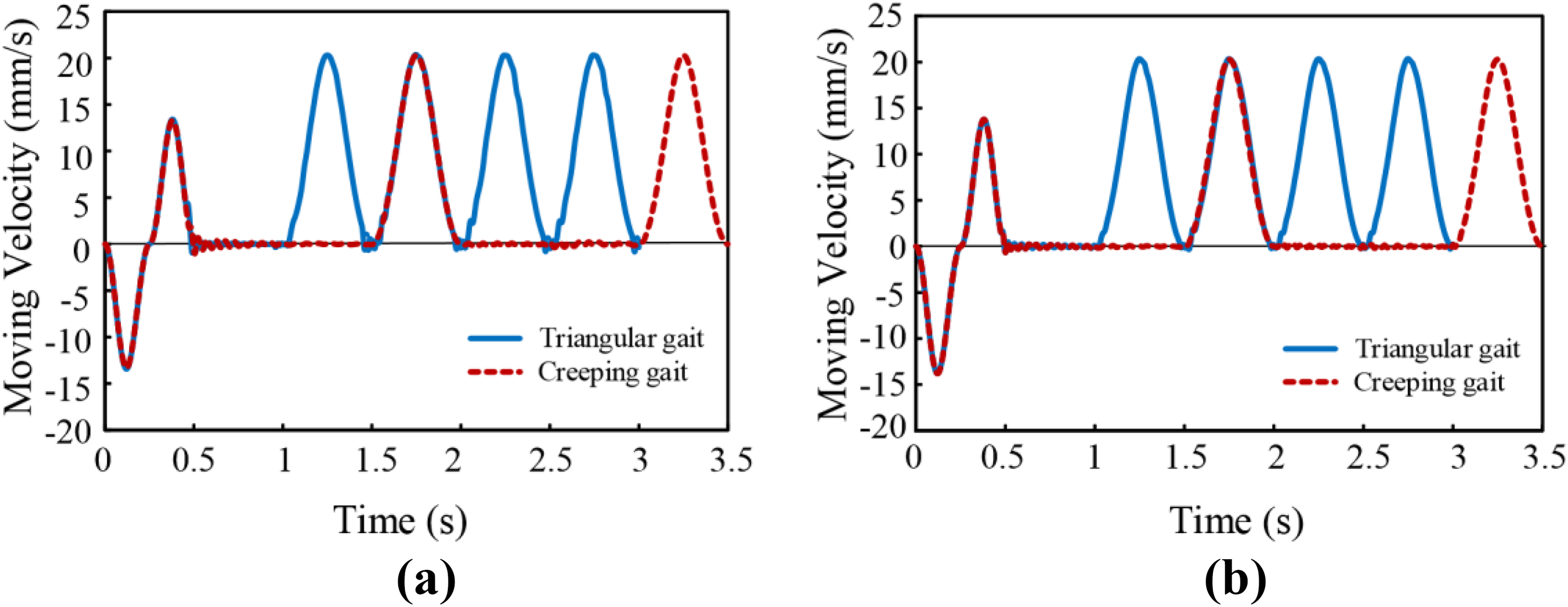
Speed of the robot’s body. (a) large-section truss rod. (b) Large-scale truss structure.
While crawling, the rotation of the hip joint drives the body to move. This movement is the same for both infrastructures and thus leads to basically the same trend of curves in the classification of infrastructures. The difference between the curves is the speed fluctuations, which are caused by the instability of the adhesion force provided by the robot’s knee joints and ankle joints when the legs and rods are in contact, so the co-simulation results are compared with respect to the crawling gaits. First, the crawling speed of the robot is analyzed. The total displacement of the robot is equal to the difference between the total displacement and inertial back-movement distance caused by the movement of the legs when adjusting the setae contact angle, and the crawling time is decreased by the time taken for the adjustments. The robot displacement and its crawling time are listed in Table 3.
Robot displacement and crawling time.

The average crawling speed of the robot on different infrastructures and gaits can be calculated


When the robot crawls on the large-section truss rod, the ratio of the average crawling speed in the triangular gait versus the creeping gait is 1.993. When the robot crawls on the large-scale truss structure, the same ratio is 1.992. Therefore, it can be concluded that the triangular gait is about twice as fast as the creeping gait for crawling speed. The triangular gait is the alternating motion of two groups of legs during which the robot body moves forward, and the creeping gait takes two groups of legs to move one by one as the robot body moves forward under its common support. Under normal circumstances, the average crawling speed ratio of the two gaits should be 2. The reason the actual ratio is slightly less than the theoretical value remains to be determined.
The average crawling speed of the robot and the fluctuation range of the adhesive force can also characterize the infrastructure adaptability of the robot. The two parameters of speed and force reflect the specific situation of the robot when crawling on different infrastructures. By comparing equations (3) and (4) with equations (5) and (6), we see that when the robot crawls on these two infrastructures with triangular gait and creeping gait, the average crawling speed on the large-scale truss structure is slightly faster than that on the large-section truss rod when employing the same pace, step frequency, and crawling gait. Additionally, by comparing equations (7) and (8) with equations (9) and (10), we can see that, in the same situation, when the robot crawls on the large-scale truss structure, the adhesive force fluctuation interval of the leg is slightly smaller than when the robot crawls on the large-section truss rod. Therefore, it can be determined that the adaptability of the robot to the large-scale truss structure is better than to the large-section truss rod.
Furthermore, owing to differences in the structure and shape of the crawling infrastructure, the contact state between the setae and the truss is also different. Figures 20 and 21 show the deformation of the setae against the two infrastructures.

Setae deformation on large-section truss rod. (a) Profile view and (b) perspective view.

Setae deformation against large-scale truss structure. (a) Profile view. (b) Perspective view.
The inside of the robot’s legs is arrays of biomimetic setae. While the contact between the large-section truss rod and legs is a large arc surface, the contact portion between the large-size truss structure and legs is a plane. When the setae contact the arc surface, as shown in Figure 17(a), they deform in a zigzag pattern. The setae are severely deformed near the tangent point of the leg and the bending deformation on both sides is small. The setae resume deformation when the leg and rod are separated. This process repeats throughout the crawl. When the setae contact the plane of the large truss structure, as shown in Figure 17(b), the overall deformation of the setae is roughly uniform, including the amount of deformation and bending direction. The recovery process is slightly different. For gecko feet, equipped with biological setae, the setae can rely on metabolic regeneration to compensate for wear due to crawling. However, the adhesive structure on the inside of the robot’s legs is artificial, and repeatedly inhomogeneous bending deformation will cause localized wear of the adhesive microstructure more severe than normal contact deformation will. This will shorten the service life of the artificial setae, increase the cycle time for renewal of the adhesion microstructure, and ultimately increase the maintenance cost of the robot. However, if all the setae are uniformly deformed, the above situation will not occur. Therefore, from the standpoint of setae deformation, we can conclude that the robot’s adaptability to large-scale truss structures is better than that of large-section truss rods. This may also explain why the ratio of the average crawling speed of the robot under the two gaits is less than the theoretical value. Different contact situations for each area of the setae cause uneven force on the legs, which in turn affects the crawl speed of the robot.
Prototype experiment
According to the structural design, the robot prototype was manufactured, as shown in Figure 22. The main material of the robot is hard aluminum alloy, which can reduce the weight while maintaining strength. Each joint relies on actuators. The adhesion microstructure is made from silicone rubber, which can overcome extreme conditions such as high and low temperatures and strong radiation. It is formed by the template pouring method and fixed inside the robot’s legs. A single piece of adhesive microstructure is shown in Figure 23.
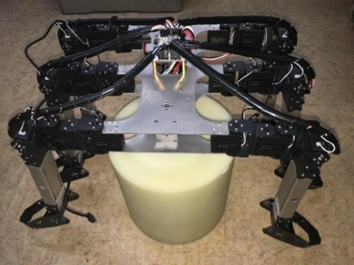
Prototype robot.

Adhesive microstructure piece.
NASA researcher Parness and Canadian scholar Henrey separately performed tests on the prepared dry adhesive material under simulated space environment conditions. The results show that the resulting van der Waals force is almost independent of temperature, pressure, and radiation conditions and the adhesion and desorption performance did not drop significantly compared to the performance in a terrestrial environment. The robot relies on the adhesion force of the legs to resist its own inertial force and crawl in space. Gravity has a great influence on the crawling process, thus the microgravity condition is a key factor in robotic crawling experiments.
We chose the suspension method to simulate a microgravity environment for the robots. The experiment platform is shown in Figure 24, including the host computer control system, crawling robot system, and gravity compensation system.

Experiment platform.
Compared with the simulation results, the displacement and speed curves of the robot on the two crawling infrastructures are basically the same. The crawling gait is an important factor affecting the curve difference. Therefore, we conducted the experiments with the crawling gait as the comparison goal.
The robot’s crawling performance with triangular gait is shown in Figure 25. Each subgraph is a screenshot at the end of each move. The transition time of the supporting leg state and the swinging leg state is equal to 1 s. Only three legs are in contact with the outer circle of the rod when the body is moving forward.

Robot crawling with triangular gait.
The crawling performance of the robot with creeping gait is shown in Figure 26. The transition time of the supporting leg state and the swinging leg state in this gait is also 1 s, but the rotation order of the main hip joint and the auxiliary hip joint has been adjusted. When the body crawls upward, the six legs of the robot are all in contact with the rod outer circle.

Robot crawling with creeping gait.
Comparing the crawling performance of the robot in two gaits, when crawling with the triangular gait, the robot body moved forward eight times, whereas crawling with the creeping gait, the robot body moved forward four times. The crawl distance is listed in Table 4.
Experimental crawling distances.
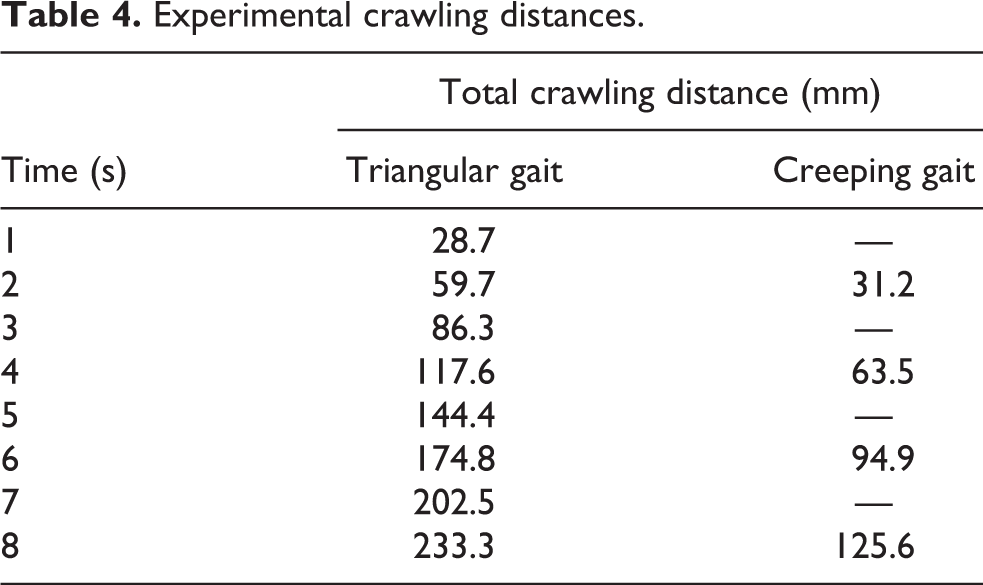
When the robot crawls with triangular gait, the two groups of legs move apart without interference. At the same time, the overlapping time of “swinging” and “supporting” state transition is substantially zero, which is in accordance with the set of the step distance and the action sequence of the legs in simulation. However, there is sloshing when the body moves. As a result, the robot cannot crawl along the axial direction of the truss rod. In contrast to this, all six legs come in contact with the rod when the robot crawls with creeping gait. The body moves forward after the two groups of legs complete the gripping motion, as seen in Figure 26. And during the whole process, the robot can move stably without obvious shaking. The average crawling speed of these two gaits are V triangle rod = 29.163 mm/s and V creeping rod = 15.700 mm/s, which are both smaller than the speed in the simulation, and the gap of triangular gait is greater. The reason is that the gripping stability with three legs is lower than that with six legs. Because of the installation accuracy and movement error of the robot, the contact status between the legs and the truss is not ideal as that in the simulation. So the adhesive force provided by the microstructure does not fully function. There is additional friction caused by the generated shaking between the longitudinal joints, the legs, and the body, which has some influence on movement stability. In general, the crawling motion of the robot prototype basically agrees with the simulation results.
Conclusion
This article presents a new type of space truss-crawling robot, which consists of multi-joint legs and an imitation gecko adhesive microstructure. To improve the adaptability of the robot, the mechanical structure and the adhesive microstructure are designed with biomimetic principles. The discrete element simulation model of the biomimetic setae and the kinematics simulation model of the robot are established in EDEM and ADAMS, respectively. The co-simulation of four schemes is conducted for two types of infrastructure and two gaits. The results show that the robot has higher stability when using the creeping gait and crawls faster when using the triangle gait. Additionally, the robot is more adaptable to large-scale truss structures than large-section truss rods. Therefore, it is best to determine the benefits of speed and stability to the movement of the robot and to select the appropriate gait according to the actual infrastructure. Finally, crawling experiments were conducted for the robot’s movement in different gaits, verifying the feasibility of the robot scheme and providing a reference for the development and further application of the robot.
Footnotes
Acknowledgements
The authors would like to thank Self-Planned Task of State Key Laboratory of Robotics and System (Harbin Institute of Technology) and Pre-research Project for Manned Space Flight.
Declaration of conflicting interests
The author(s) declared no potential conflicts of interest with respect to the research, authorship, and/or publication of this article.
Funding
The author(s) disclosed receipt of the following financial support for the research, authorship, and/or publication of this article: This work was supported by Self-Planned Task of State Key Laboratory of Robotics and System (Harbin Institute of Technology) and Pre-research Project for Manned Space Flight.