
Abstract
Obstacle avoidance is of great importance for path planning of manipulators in dynamic environment. To help manipulators successfully perform tasks, a method of path planning with obstacle avoidance is proposed in this article. It consists of two consecutive phases, namely, collision detection and obstacle-avoidance path planning. The collision detection is realized by establishing point-cloud model and testing intersection of axis-aligned bounding boxes trees, while obstacle-avoidance path planning is achieved through preplanning a global path and adjusting it in real time. This article has the following contributions. The point-cloud model is of high resolution while the speed of collision detection is improved, and collision points can be found exactly. The preplanned global path is optimized based on the improved D-star algorithm, which reduces inflection points and decreases collision probability. The real-time path adjusting strategy satisfies the requirement of reachability and obstacle avoidance for manipulators in dynamic environment. Simulations and experiments are carried out to evaluate the validity of the proposed method, and the method is available to manipulators of any degree of freedom in dynamic environment.
Introduction
Manipulators have raised their intelligence level in recent years, and they are no longer confined to help or replace human beings to complete the onerous and complex tasks only in static environment. The application of manipulators in dynamic environment is of increasing importance, such as space manipulators in outer space. 1 Obstacles usually move in dynamic environment. If collision occurs, tasks cannot be accomplished and damage will be caused to manipulators even operators. Hence, to help manipulators execute tasks successfully in dynamic environment, a path planning method with obstacle avoidance is an urgent necessity. 2 –4
To plan an obstacle-avoidance trajectory in real time, various sensors are used to obtain the position information of obstacles, 5 and a path planning method with obstacle avoidance is applied. More specifically, the environment is unknown with stationary obstacles or moving obstacles; hence, particular attention is given to reactive methods based on local sensory data. 6 A collision detection algorithm is used to judge the risk of collision based on the position information of obstacles. Then, a path planning method is adopted to help manipulator avoid obstacles if collision is predicted to occur. 7 Thus, the process indicates that planning an obstacle-avoidance trajectory in dynamic environment consists of two consecutive phases, namely, collision detection and obstacle-avoidance path planning.
A great deal of research on collision detection algorithm has been carried out, which can be divided into image-based collision detection algorithm and graph-based collision detection algorithm from the perspective of spatial dimension. 8 The image-based collision detection algorithm is always affected by image resolution, which is a limitation for the algorithm. 9 In the graph-based collision detection algorithm, the simulation model is divided into sets by analyzing the three-dimensional (3-D) graph, and collision can be detected rapidly. The graph-based collision detection algorithm has two frequently-used categories, including spatial-based segmentation algorithm and hierarchical bounding volume algorithm. The hierarchical bounding volume algorithm can rapidly identify potential intersections, improving the efficiency of collision detection. It is widely applied now and includes several common methods: sphere bounding box, 10 axis-aligned bounding box (AABB), 11,12 oriented bounding box (OBB), 13 and discrete-orientation polytopes. 14 Compared to the other three methods, AABB method has many advantages: easy construction, small storage capacity, and good real-time property. So it is suitable for collision detection in dynamic environment.
However, the existing AABB method has several problems. The tightness of enclosing an object is relatively poor, which leads to low resolution. Moreover, obtaining collision points exactly is difficult when model resolution is low. Thus, to improve the model resolution and obtain collision points, a collision detection algorithm is proposed in this article, which combines the AABB method with point-cloud model.
After the collision detection algorithm in dynamic environment is proposed, a path planning method with obstacle avoidance is applied. 15 Some existing methods include configuration-space(C-space) method, artificial potential field method, gradient projection method, genetic algorithm, and A-star (A*) algorithm. C-space method 16 can realize path planning and obstacle avoidance, but the calculation is complex and trajectory searching requires a long time, causing that the method could not meet real-time requirement. Artificial potential field method 17 is simple and widely used, but it is easily trapped to local minima, resulting in task failures. Gradient projection method 18 is not universal and may not be suitable to be applied in nonredundant manipulators. Genetic algorithm 19 is slow to converge, and results easily fall into local optimum. A* algorithm 20 is efficient for searching the shortest path, and it can realize collision-free path planning for manipulators in static environment. However, A* algorithm is not applicable in dynamic environment. Developed on A* algorithm, D-star (D*) algorithm 21,22 is applicable for manipulators to search a reachable path in dynamic environment and avoid obstacles in real time. However, the trajectory obtained through D* algorithm has many inflection points which results in manipulator’s stopping and starting frequently, and the trajectory is easily close to obstacles, increasing the collision probability and causing a poor real-time performance. Thus, a path planning method with obstacle avoidance based on the improved D* algorithm is proposed in this article. A preplanned global path is optimized with the known environment information and adjusted locally with the collision detection results; thus, the abovementioned two challenges are addressed.
In summary, aimed at manipulators in dynamic environment, a path planning method with obstacle avoidance is studied in this article, including the collision detection algorithm and the path planning method. The main contributions of this article include the following. First, a method for collision detection is proposed, which combines point-cloud model and the AABB method. It can keep high resolution of the point-cloud model and help find exact collision points when a collision is detected to occur. At the same time, detection is speeded up by the intersection testing method of AABBs trees. Second, D* algorithm is improved by introducing nominal parent nodes. Thus, the preplanned global path is optimized, and the number of inflection points is decreased, improving the motion stability of manipulators. Finally, a path planning method with obstacle avoidance based on the improved D* algorithm is designed to help manipulators to avoid obstacles once the collision detection results are obtained. By generating collision danger zone in dynamic environment and applying a real-time path adjusting strategy, obstacle-avoidance path planning for manipulator is realized. The trajectory planned by this method can satisfy the requirements of reachability and obstacle avoidance. The method presented in this article is universal and suitable for manipulators with any degree of freedom (DOF).
The remainder of this article is organized as follows. In “Collision detection based on point-cloud model” section, the point-cloud model of manipulator is established, and a collision detection algorithm is proposed. Then, a path planning method with obstacle avoidance is designed in “Obstacle-avoidance path planning” section. The validity of the collision detection algorithm and the path planning method are verified in “Simulation study” section. Finally, the conclusion is presented in the last section.
Collision detection based on point-cloud model
Point-cloud model
In collision-detection modeling methods for manipulators, some simple geometrical bodies such as cubes or cylinders are usually used to fully enclose the manipulator. However, the manipulator is a complex multi-body system and requires a high operating precision, if the manipulator is enclosed just by some basic geometrical bodies, the modeling error is large and the model could not satisfy high-resolution requirement. When the model resolution is improved through a larger quantity of basic geometrical bodies, the workload of pre-enclose processing is increased, which may not be suitable for collision detection. The point-cloud model, 23 which uses discrete points to construct the profile of the manipulator, could have a higher resolution easily, providing a better performance for collision detection. So considering these advantages, the point-cloud model of manipulator is established in this article.
The irregular object in Figure 1 is given as an example to explain how to create a point-cloud model through 3-D computer scanning technique. First, rays are uniformly generated which are parallel to three axes in the local coordinate system, and they pass through the object. As shown in Figure 1(a), rays that are parallel to the X-axis pass through the object and intersection points on the surfaces of the object are obtained. Figure 1(b) shows intersection points formed on a surface. And the set of all intersection points formed on surfaces of the object is taken as the point-cloud model. The interval between rays, denoted as ε, represents the model resolution. The smaller the ε, the higher the model resolution.

Schematic of creating the point-cloud model: (a) rays passing through an object and (b) intersection points formed on the surfaces of the object.
An 8-DOF modular manipulator is shown in Figure 2(a). The creation process of its point-cloud model is shown in Figure 2(b). Each module of the manipulator is processed through the abovementioned method, respectively, including joints and links, and eight sub point-cloud models can be obtained. The whole point-cloud model of manipulator can be described as

Point-cloud model creation of the manipulator: (a) 8-DOF modular manipulator and (b) point-cloud model of the modular manipulator. DOF: degree of freedom.
Thus, in this way, we can obtain the point-cloud model of the manipulator. It could provide fundamental data to determine whether manipulator collides with itself or other objects in dynamic environment. The process to create a point-cloud model is easy and fast because the rays generation and model obtainment are automatic through 3-D computer scanning technique. Moreover, the resolution of point-cloud model can be easier to change, and we can change ε to satisfy the model resolution requirement in different tasks.
Collision detection algorithm
After the whole point-cloud model of the manipulator is generated, collision detection can be translated into the distance calculation between two models (such as two sub point-cloud models of the manipulator). However, the manipulator is a multi-body system, and its whole point-cloud model has numerous points. If we determine whether collision occurs by individually calculating the distance between points of two models, the computational cost would be high and collision detection would be time-consuming. Considering the AABB method can be used to make collision detection faster; therefore, through combining the point-cloud model with the AABB method, a collision detection algorithm is proposed in this article.
Generation of an AABBs tree
One point-cloud model can be divided into clusters (a set of some points in close proximity) through a simple top–down approach; thus, a hierarchical tree is obtained first. Then, through constructing AABBs of clusters, the corresponding AABBs tree is generated.
When the point-cloud model is divided into clusters, the model is regarded as the root cluster

where
According to the abovementioned method of generating clusters, a hierarchical tree of a point-cloud model can be obtained. Then, AABBs are constructed for all clusters and an AABBs tree is obtained. As shown in Figure 3, an AABBs tree corresponding to a two-dimensional point-cloud model is generated. The red arrowed line denotes the longest axis, and the dotted line denotes the separating line so every parent cluster can be divided into two parts. The rectangle enclosing a cluster is the AABB of the cluster. There is a separating surface instead of the separating line when the model is in 3-D circumstances.

Schematic of generating an AABBs tree. AABB: axis-aligned bounding box.
As for an AABBs tree, every tree node stores information of the corresponding bounding box, containing its geometric center coordinate and its dimensions. Note that every leaf node contains only one point; thus, we need to set the edge length of its bounding box, which is also defined as safe distance β. The safe distance indicates that two bounding boxes of leaf nodes have certain overlaps if the distance between their centers is less than β. Because ε is the shortest distance between adjacent points of a point-cloud model, a collision would occur if the distance between two points is less than ε. Thus, β ≥ ε.
Intersection tests of AABBs trees
To expound the proposed collision detection algorithm, collision detection between two links of the manipulator is taken as an example. Their corresponding AABBs trees are denoted as TreeA and TreeB separately, and collision detection is carried out through intersection tests among their AABBs.
A bounding box in the base coordinate system can be described as

where C is the vector of center coordinates of the bounding box in the base coordinate system, Cu
is the vector of center coordinates of the bounding box in the local coordinate system, S and Su
are the dimensions of the bounding box correspondingly, and
The criteria determining whether collision occurs between two bounding boxes are as follows
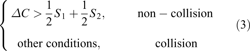
where
When we need to detect whether two bounding boxes collide with each other, we name them after TNA and TNB, respectively. Function “aabbcollision” is designed to deal with collisional cases between TNA and TNB; then, the recursion is introduced, as shown in Figure 4.

Recursion function. Four types of collision are shown in the dotted box.
In Figure 4, “leafbox” represents a bounding box which encloses a leaf node; “leftchild” and “rightchild” represent the bounding box enclosing the left child cluster and the bounding box enclosing the right child cluster, respectively.
According to Figure 4, the collision detection process is as follows
Step 1: The two root bounding boxes of Tree A and Tree B are the first pair of bounding boxes to be detected, go to step 2.
Step 2: Use the criteria in equation (3) to determine whether collision occurs between two bounding boxes. If no collision occurs, go to step 5; otherwise, go to step 3.
Step 3: Four collision types are shown in the dotted box in Figure 4. Judge that the collisional case between two bounding boxes belongs to which type.
Case 1: If TNA and TNB are leafboxes, go to step 4.
Case 2: If TNA is a leafbox but TNB is not, go to step 2 to detect whether collision occurs between TNA and two corresponding bounding boxes of TNB’s child clusters, respectively.
Case 3: If only TNB is a leafbox, go to step 2 to detect whether collision occurs between two corresponding bounding boxes of TNA’s child clusters and TNB, respectively.
Case 4: If TNA and TNB are not leafboxes, go to step 2 to detect whether collision occurs between two corresponding bounding boxes of TNA’s child clusters and two corresponding bounding boxes of TNB’s child clusters, respectively.
Step 4: The midpoint of line connecting two leaf nodes is regarded as the collision point and its coordinates can be obtained.
Step 5: No collision occurs between two parts represented by the two bounding boxes, and collision detection would not continue between their children.
As can be seen from the abovementioned process, if no collision occurs between two bounding boxes, the detection would not continue between their child, which can save detecting time and improve computational efficiency. If collision occurs between two bounding boxes, the detection will continue in parallel between their children, which can also improve computational efficiency.
Therefore, in the proposed collision detection algorithm, the point-cloud model retains high resolution, and the detecting speed is improved by intersection tests of AABBs trees, instead of all points of point-cloud model. Moreover, we can obtain collision points if collision occurs, which will provide data for applying path planning method later.
Obstacle-avoidance path planning
Based on the collision detection algorithm proposed in this article, once a collision is detected to occur, a path planning method for manipulator considering obstacle-avoidance ability is deemed essential. D* algorithm is suitable to be applied in dynamic environment, but it has the shortage of unsmooth motion performance and its real-time property could be improved. Therefore, a path planning method with obstacle avoidance based on the improved D* algorithm is proposed in this article.
Path preplanning and optimizing
D* algorithm, a heuristic searching algorithm developed on A* algorithm, is applicable to dynamic environment. The path planning method with obstacle avoidance in dynamic environment is based on the improved D* algorithm in this article. With the consideration of moving obstacles in dynamic environment, the method consists of two steps, the global path preplanning and the real-time path adjustment. In view of existing environmental information and the requirements of tasks, a global path for manipulator is preplanned and optimized first based on the improved D* algorithm.
When the manipulator searches the global path, the spatial field is rasterized, and some grid cells are generated. If node q in a grid cell is to be a path node, the next path node will be searched in the adjacent grid cells. Some nodes in adjacent grid cells are reachable for the end-effector of manipulator, and then, we should consider the configuration of the manipulator. For each reachable node, we will detect whether the manipulator would collide in the workspace through the proposed collision detection algorithm. And the nodes, which can satisfy the configuration constraint and realize collision-free path of manipulator, are the feasible nodes.
For these feasible nodes, we will choose the optimal one in virtue of optimization index. The cost function is applied when we choose an optimal node, which can be expressed as

where p denotes a feasible node in one adjacent grid cell; f(p) denotes the cost value from the start point to the endpoint passing node p, and g(p) denotes the cost from the start point to node p when h(p) is the cost from node p to the endpoint.
If the current node Q is supposed to be the parent node of feasible nodes in adjacent grid cells, and the start point of path is the first parent node, the formula to calculate cost value g(p) can be expressed as

where pf
denotes the parent node of p and
For different tasks, different optimization indexes can be chosen as the calculation basis of
Schematic of global path preplanning and optimizing: (a) global path preplanning and (b) global path optimizing through introducing the nominal parent node.
Therefore, a global path considering environmental information and task requirements is preplanned through the D* algorithm. However, due to the characteristic of fixed step size when searching path nodes, the generated global path has a lot of unnecessary inflection nodes. Too many inflection nodes tend to increase the number of the times of stopping and starting of the manipulator, causing motion discontinuity and unnecessary turning. To address the challenge, D* algorithm is improved by introducing nominal parent nodes, and the global path is optimized.
The start point is supposed to be the nominal parent node of itself, for every path node q preplanned before, the principle to obtain the nominal parent node can be expressed as

where qf is the parent node of q and qg is the nominal parent node of qf .
As described in formula (6), cost value g(q) is the minimum value by comparing two calculation results, and the node corresponding to minimum value is set as the nominal parent node of q. To be specific, if the result is smaller when qf is substituted into the calculation of g(q), qf would be the nominal parent node of q; if the result is smaller when qg is substituted into the calculation of g(q), qg would be the nominal parent node of q.
After the nominal parent node is introduced, when calculating the actual cost value, the traditional way of “the cost from the start point to the parent node” plus “the cost from the parent node to the current node” is abandoned, but the way of “the cost from the start point to the nominal parent node” plus “the cost from the nominal parent node to the current node” is adopted. Thus, if pf′ is the nominal parent node of p, the calculation of the cost value g(p) is improved as

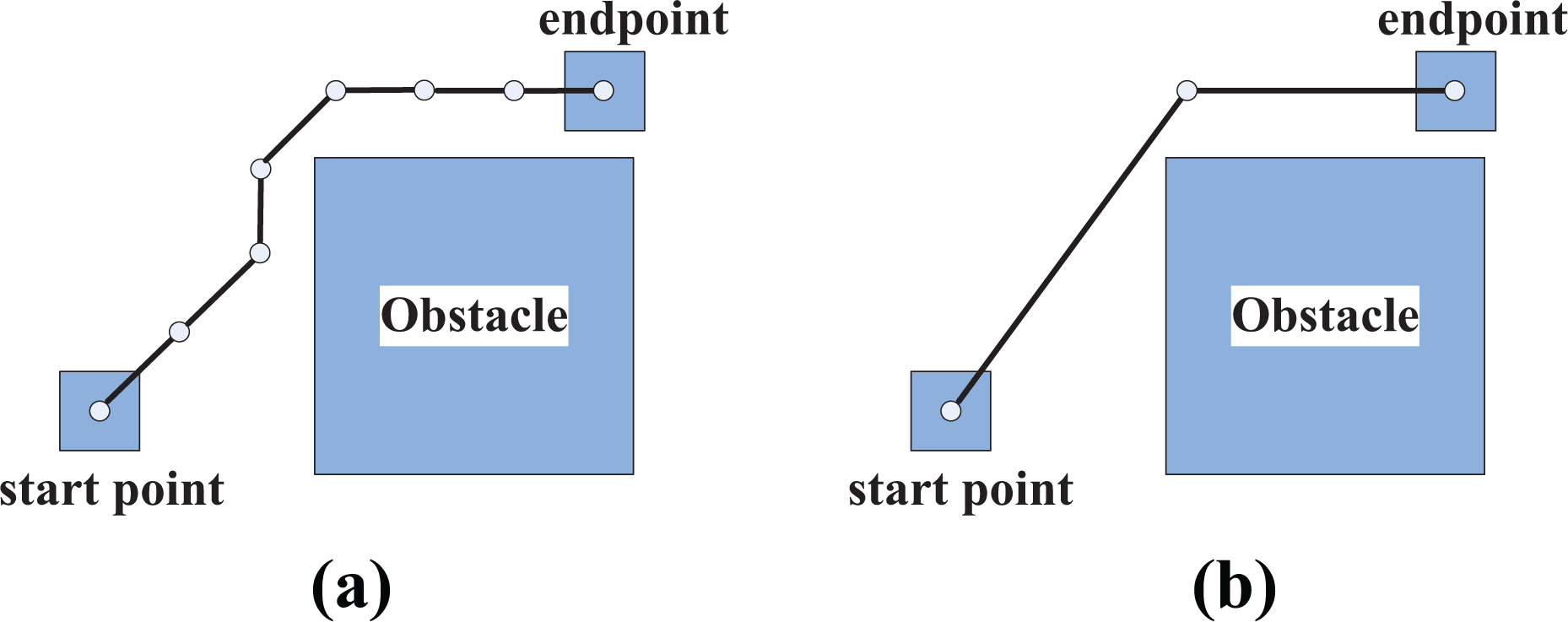
Thus, as shown in Figure 5(b), the optimized global path will link all nominal parent nodes from the start point to the endpoint, and an optimized global path with fewer inflection points is obtained. Through the improved D* algorithm, the number of inflection points is decreased, reducing the number of the times of manipulator’s stopping and starting and improving the motion stability of the manipulator.
Real-time obstacle-avoidance path adjusting
For a manipulator in dynamic environment, in order to avoid obstacles and reach the endpoint in real time, a path adjusting strategy with obstacle avoidance needs to be designed with the preplanned global path. The collision danger zone in dynamic environment is set to improve the D* algorithm at first.
Collision danger zone
When we preplan the global path, we would obtain the point-cloud model of the manipulator and the environmental information of the preexisting obstacles. In this way, we can detect the collision to choose feasible nodes. Then, if an obstacle is detected to move in the environment, the preplanned path would be adjusted locally with obstacles information. However, the adjusted path may keep close to obstacles, especially for an unknown obstacle. Because when an unknown moving obstacle bursts in, its general shape is obtained through sensors, but it is difficult to obtain its point-cloud model of high resolution. And the adjusted path which keeps close to these obstacles will increase the collision possibility. Thus, to solve the problem, the D* algorithm is improved by introducing collision danger zone in this article.
To identify the collision danger zone, first unknown obstacles in dynamic environment need to be dealt with. Since it is difficult to obtain the point-cloud model of an unknown moving obstacle, the OBB method is used to enclose the obstacle. Moreover, considering the obstacle may rotate around itself, we further build the outer sphere of the obstacle to improve manipulator security. The method to enclose a moving obstacle is shown in Figure 6.

Schematic of enclosing a moving obstacle: (a) OBB enclosing the moving obstacle and (b) outer sphere enclosing the obstacle. OBB: oriented bounding box.
Sensors will monitor the environmental changes and moving obstacles in real time, and then, the general shape and running path of obstacles are obtained. We can classify all the running space grids of manipulator into dangerous grids and safe grids, as shown in Figure 7. All the dangerous grids are the space grids that obstacle spheres occupy. The set of all of dangerous grids is defined as the collision danger zone. The dotted border in Figure 7 is the projection of the bounding box and sphere of an unknown running obstacle.

Schematic of collision danger zone. The set of all of dangerous grid is defined as the collision danger zone.
As can be seen from Figure 7, the manipulator is more likely to collide with obstacles in the collision danger zone, whose size is related to the size of the enclosing sphere. Based on the collision danger zone, the problem of path keeping close to unknown obstacles is solved, and the real-time property to avoid obstacles is improved.
Real-time path adjusting strategy
When the manipulator is running in dynamic environment, the collision danger zone is obtained in real time and the collision detection algorithm is applied. If a collision is detected to occur, the manipulator will adjust the path to satisfy a collision-free motion. Thus, a real-time path adjusting strategy is proposed here.
The manipulator will backtrack the global path in dynamic environment. On the basis of collision detection algorithm, the process of path adjusting strategy to avoid obstacle is as follows.
Step 1: Based on the results of collision detection, judge whether the sub-path between the current node and its nominal parent node passes the collision danger zone when manipulator running along the global path in real time, if so, go to step 2. Otherwise, just run on without adjustment and go to step 4.
Step 2: Regard the nominal parent node of the current node as an unfeasible node. Judge whether the sub-path between the current node and its parent node passes the collision danger zone, if so, go to step 3. Otherwise, adjust the path and reach to its parent node, and go to step 4.
Step 3: Regard the parent node of the current node as an unfeasible node. Utilize the improved D* algorithm to search for all feasible nodes around the current node and find the node corresponding to the minimum value of cost function f(p). Let the end-effector of the manipulator move to this node and go to step 4.
Step 4: Judge whether the manipulator reaches the target point, if so, the process to adjust an obstacle-avoidance path is over. Otherwise, go to step 1.
For step 3, when calculate the value of cost function f(p), we will set the collision distance as a major optimization index. If a collision is detected to occur and collision points are obtained, the collision distance will be calculated, and the manipulator adjusts the path locally.
The real-time path adjusting process is aimed at three different cases of collision.
Case 1: The sub-path between the current node and its nominal parent node is safe.
Case 2: The sub-path between the current node and its nominal parent node passes the collision danger zone.
Case 3: The sub-path between the current node and its parent node passes the collision danger zone.
According to the abovementioned process, the flowchart is shown in Figure 8.

Flowchart of obstacle-avoidance path planning method for manipulator in dynamic environment.
To demonstrate the strategy clearly, the obstacle-avoidance path from point A to point B needs planning and adjusting for manipulator, as shown in Figure 9. According to the proposed method, the global path with nominal parent nodes based on the improved D* algorithm is obtained first. Then combined with the results of collision detection, the path adjusting locally is finished until the target point is reached.

Real-time path adjusting to avoid obstacles: (a) global path preplanning and optimizing and (b) path adjusting in dynamic environment.
From the abovementioned analysis, based on the results of collision detection, the real-time path adjusting strategy on the improved D* algorithm is designed. Generally speaking, the path for manipulator in dynamic environment is completed through preplanning, optimizing, backtracking, and adjusting. Because the manipulator model is of high resolution and the speed of collision detection is improved in this article, valid collision information can be fed back timely. Then, the information of the optimized global path is used, and D* algorithm is improved through introducing the collision danger zone, obstacle-avoidance path planning with good real-time property in dynamic environment could be reached.
Simulation study
Modeling of 8-DOF modular manipulator
Before validating the effectiveness of the proposed methods, the 3-D visualization model and the coordinate systems of 8-DOF modular manipulator are shown in Figure 10(a) and (b), respectively. The Denavit–Hartenberg (DH) method is used to create kinematic model of the modular manipulator, and DH parameters are shown in Table 1.

8-DOF modular manipulator: (a) 3-D visualization model of the modular manipulator and (b) coordinate systems of the modular manipulator. DOF: degree of freedom.
DH parameters of the modular manipulator.

DH: Denavit–Hartenberg.
The point-cloud model of the modular manipulator is obtained through 3-D computer scanning technique, as shown in Figure 2. Then, simulations and experiments based on the point-cloud model are completed. (1) For the proposed collision detection algorithm, a case is in need when we validate its performance. (2) For the proposed path planning method with obstacle avoidance, the preplanned global path is optimized first, and then the effectiveness of the proposed path planning method with obstacle avoidance is validated.
Simulation results of the collision detection algorithm
In order to fully illustrate the effectiveness of the proposed collision detection algorithm, several simulations are carried out.
Simulations comprise two main aspects. To validate the correctness of the algorithm, we first set different configurations of the modular manipulator and have a comparison in collision detection results. Afterward, to study the relationship between model resolution with detecting speed and find which model resolution is more suitable to apply in collision detection, we set different model resolution for each configuration of the modular manipulator.
In the simulations, a set of manipulator configurations which approach collision points gradually is used as a testing case. The joint angles of these manipulator configurations are listed in Table 2.
Manipulator configurations.
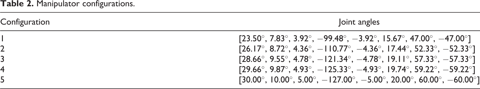
Figure 11 shows the 3-D visualization models corresponding to these configurations, respectively. Among them, Figure 11(a) to (e) corresponds to configurations 1 to 5, respectively. In the local enlarged drawing of Figure 11(d) and (e), no collision occurs when the modular manipulator is in configuration 4, but a collision occurs when the modular manipulator is in configuration 5.

3-D visualization models to manipulator configurations: (a) configuration 1, (b) configuration 2, (c) configuration 3, (d) configuration 4, and (e) configuration 5. 3-D: three-dimensional.
The collision detection algorithm is applied corresponding to the abovementioned five manipulator configurations. To show the advantages of the collision detection algorithm and guarantee the model resolution in a relatively high level, ε of point-cloud model is confined to 0–5 mm. So for each manipulator configuration, ε of point-cloud model is set as 1, 1.5, 2, 2.5, 3, 3.5, 4, and 4.5 mm to obtain point-cloud models of different resolution. And we set β = ε. To reduce the error of collision detection, for different configurations and different resolution models, testing results of 100 times are averaged. The averaged result is set as the elapsed time. Therefore, for each manipulator configuration, a curve of elapsed time can be plotted under different resolution. Figure 12(a) to (e) shows five curves corresponding to configurations 1 to 5. The horizontal coordinate axis is the value of ε. The vertical coordinate axis is the elapsed time of collision detection.

Elapsed time of collision detection: (a) configuration 1, (b) configuration 2, (c) configuration 3, (d) configuration 4, and (e) configuration 5.
From the trend of curves shown in Figure 12, the elapsed time of collision detection will decrease when ε increases. As previously mentioned, the value of ε represents the model resolution. The larger the ε, the lower the model resolution. Thus, the elapsed time will increase when the model resolution increases. In Figure 12, the elapsed time of collision detection decreases greatly when ε is set in 1.5–2 mm and the decline in the back part of the curve is not obvious. When ε is set in 2–3 mm, the model resolution is high and the elapsed time is less than 150 ms. Thus, to guarantee model resolution and detecting speed, the point-cloud model can be chosen in practical application when the model resolution is in 2–3 mm.
Furthermore, when the modular manipulator approaches collision points gradually, the elapsed time of collision detection increases. This is because the number of times of intersect tests of bounding boxes is increasing. However, the correctness of judging whether collision occurs is not influenced. In Table 3, for configuration 5, the test result that a collision occurs is accordant with Figure 11(e), and collision points are obtained. If the model is constructed through triangular facets, which is a typical modeling method in collision detection, the collision points would not be predicted exactly. This is because the area of triangular facet would be large for an object with a regular shape in collision detection. But the modular manipulator happens to have modules with a regular shape. Two intersecting triangular facets could be obtained but the collision points could not be gained. Thus, finding collision points exactly is another advantage of the proposed algorithm based on the point-cloud model.
Collision detection results of configuration 5.

Therefore, good effectiveness of the collision detection algorithm is verified. In summary, the resolution of point-cloud model can be adjusted under different tasks. When the collision detection method is applied, the model is of high resolution and the detecting speed could satisfy applicative requirements. Moreover, collision points are obtained, which would provide a fundamental data for obstacle-avoidance path planning.
Simulations and experiments of the path planning method with obstacle avoidance
To prove the validity of the path planning method with obstacle avoidance in dynamic environment, simulations and experiments are conducted. First, simulations of a preplanned global path with and without optimization are both carried out. A comparative analysis of simulation results comes to illustrate the optimization effect. Then, simulations of the modular manipulator with and without the path planning method with obstacle avoidance are carried out, respectively. And a comparative analysis of simulation results is made. Finally, an experiment of the modular manipulator applying the proposed path planning method to avoid obstacles in dynamic environment is performed.
Simulations of optimization on preplanned global path
Simulations on global path preplanning and optimizing are conducted first. The simulation design: The initial point and the target point are selected randomly within the reachable range of the manipulator end-effector. The initial position and pose of the manipulator end-effector is [−0.64 m, 0.40 m, 0.66 m, 135.96°, −85.70°, −135.00°], and the target position and pose is [0.64 m, 0.32 m, 0.87 m, 0.00°, 0.00°, 0.00°]. Path length is chosen as the calculation index of cost function, and the maximum joint angular velocity is set as 30° s−1. A velocity trapezoidal path planning algorithm is used to preplan the sub-path between two inflection points. The total time for each planning is 20 s, and the acceleration time is 2 s.
The simulation results on global path preplanning without optimization are shown in Figure 13. As can be seen from Figure 13, the global path of the manipulator end-effector is divided into four parts from the initial point to the target point.

Path preplanning without optimization: (a) initial stage of preplanning, (b) mid-stage of preplanning, and (c) final stage of preplanning.
Three inflection points are created, whose position and pose are shown in Table 4, respectively.
Position and pose of the end-effector corresponding to inflection points of path without optimization.

Then, the optimization of preplanned global path is conducted to verify the optimization effect. The simulation results are shown in Figure 14.

Path preplanning with optimization: (a) initial stage of preplanning, (b) mid-stage of preplanning, and (c) final stage of preplanning.
From Figure 14, the optimized global path from the initial point to the target point is divided into two parts, and only one inflection point exist, whose position and pose are shown in Table 5.
Position and pose of the end-effector corresponding to inflection point of path after optimization.

Then, results about end acceleration changes of the modular manipulator with and without the optimization are obtained, as shown in Figure 15. The end acceleration of the modular manipulator after optimization still remains within the threshold range, and the number of times of manipulator’s stopping and starting is decreased from 4 to 2. Thus, after the optimization of preplanned global path, the number of times of manipulator’s stopping and starting decreases a lot and the manipulator motion is smoother.

End acceleration changes of the modular manipulator. The blue curve is the end acceleration changes before optimization, and the red curve is the end acceleration changes after optimization.
Therefore, after introducing the nominal parent node, the number of inflection points decreases, and the number of times of manipulator’s stopping and starting is also reduced, decreasing the number of times of acceleration changing of the end-effector. Thus, the stability of the manipulator in real-time motion is improved.
Simulations of the path planning method with obstacle avoidance
Simulations to verify the effectiveness of the path planning method with obstacle avoidance are conducted here. The simulation design: The initial point and the target point are selected randomly within the reachable range of the manipulator end-effector. The initial position and pose of end-effector is [−0.66 m, 0.17 m, 0.55 m, −170.06°, −83.00°, −179.94°], and the target position and pose is [−0.63 m, 0.69 m, 0.83 m, 81.42°, −16.61°, 88.85°]. And the obstacle is assumed to be a moving cuboid in dynamic environment, which can change its position in real time. The modular manipulator using the path planning method with obstacle avoidance and the modular manipulator without this method are simulated, respectively. The simulation results are shown in the following.
If the path planning method with obstacle avoidance is not used in dynamic environment, the planned path for the modular manipulator is only a straight trajectory from the initial position and pose to the target position and pose, and the obstacle cannot be avoided. The manipulator motion in dynamic environment is shown in Figure 16(a) to (c). The collision occurs between the modular manipulator and the obstacle. And the local enlarged drawing of collision is shown in Figure 16(c). Therefore, there are some limitations when the modular manipulator moves in dynamic environment without the path planning method with obstacle avoidance.

Simulation results without the obstacle-avoidance path planning method: (a) initial position and pose, (b) target position and pose, and (c) local enlarged drawing of collision.
If the real-time path planning method with obstacle avoidance is applied, the planned path for manipulator can not only reach the target position and pose successfully, but also avoid the moving obstacle timely. The motion of the modular manipulator in dynamic environment is shown in Figure 17(a) to (c).

Simulation results with the obstacle-avoidance path planning method: (a) initial position and pose, (b) path adjusting to avoid obstacle, and (c) obstacle-avoidance path comprised of three parts: AB, BC, and CD.
From Figure 17, the manipulator could detect the collision between itself and the moving obstacle, and an obstacle-avoidance path is generated based on the collision detection information. The path can be divided into three parts: AB, BC, and CD. The moving obstacle could be avoided successfully and no collision occurs.
Experiments of the path planning method with obstacle avoidance
To verify the effectiveness of the path planning method with obstacle avoidance for manipulator in the practical environment, an experiment platform is designed to carry out experiments. The platform is composed of a modular manipulator, a control computer, and other auxiliary tools. A laser ranger finder is installed on a tripod to detect the obstacle in environment. A part of the platform is shown in Figure 18. The software to model and control the manipulator is developed in Microsoft Visual Studio 2010 [version flagship]. The experiment design: The initial position and pose of end-effector is [−0.66 m, 0.17 m, 0.55 m, −170.06°, −83.00°, −179.94°], and the target position and pose is [−0.63 m, 0.69 m, 0.83 m, 81.42°, −16.61°,88.85°]. Path length is chosen as the calculation index of cost function, the maximum joint angular velocity is set as 30° s−1. A box is assumed to be a moving obstacle, whose velocity is not a constant value. It gradually draws near to the modular manipulator along one direction and its motion is observed by environmental sensor. The motion of the modular manipulator in actual dynamic environment is shown in Figure 19(a) to (d) to demonstrate the real-time obstacle-avoidance capability of the manipulator.

The experiment platform. The platform is imposed of a modular manipulator, a control computer, and other auxiliary tools.

Experiments of manipulator avoiding an obstacle in real time. (a) Path from the initial point, (b) path adjusting to avoid obstacle, (c) path after obstacle avoidance, and (d) path to the target point.
As shown, at the beginning of the task, when the obstacle kept far from the modular manipulator, the end-effector moved along the preplanned path. The motion of the obstacle was detected. When it drew close to the modular manipulator gradually and was detected to have an influence on the operation of the modular manipulator, the modular manipulator changed its preplanned path locally to avoid the moving obstacle. And when the obstacle was out of the safe distance to the modular manipulator and the end-effector went further away from the obstacle, the end-effector moved along the preplanned path again and reached the target.
Through Figure 19, after utilizing the path planning method with obstacle avoidance, the modular manipulator can monitor the dynamic obstacles in real time and adjust the preplanned path in time to avoid collision. The modular manipulator can arrive at the target point safely, and its movement is marked in Figure 19. Thus, the real-time property and obstacle-avoidance effectiveness of the proposed path planning method are verified.
Conclusion
In this article, a path planning method with obstacle avoidance for manipulators in dynamic environment is studied, including the collision detection algorithm and the path planning method. The main contributions of this article include (1) combined with AABB method, a collision detection algorithm based on point-cloud model is proposed. The point-cloud model is of high resolution, and the collision detecting speed is improved. Moreover, the model resolution can be adjusted, and collision points can be found exactly, making the collision detection method more adaptable in practical environment. (2) With the results of collision detection, a path planning method with obstacle avoidance based on the improved D* algorithm is proposed, to assist manipulators to avoid obstacles and complete the task successfully in dynamic environment. The traditional D* algorithm is improved by introducing the nominal parent node and collision danger zone, which can reduce the number of the times of manipulator’s stopping and starting and decrease the collision probability. The results of simulations and experiments verify the feasibility of the proposed methods, and the path planning method with obstacle avoidance is applicable to manipulators under changeable operating environment.
Footnotes
Declaration of conflicting interests
The author(s) declared no potential conflicts of interest with respect to the research, authorship, and/or publication of this article.
Funding
The author(s) disclosed receipt of the following financial support for the research, authorship, and/or publication of this article: This work was supported by the National Natural Science Foundation of China (nos 61403038 and 61573066), the Fundamental Research Funds for the Central Universities (nos 2018PTB-00-10), and the Open Research Fund of the Key Laboratory of Space Utilization, Chinese Academy of Sciences (no. LSU-2016-05-2).