
Abstract
Since many off-the-shelf motor drives are supplied with complete control capability in the current, velocity and position loop, the robot model in the navigation control architecture can be oriented either to kinematics, interfaced with the velocity loop, or to dynamics, with the motor-current loop. Moreover, no constraints are imposed by a caster on the mobility of differential-driving mobile robots. Hence, a reduced model, containing only the platform, is sufficient for navigation control based only on the robot kinematics. However, if the multibody system model is used for navigation control based on the robot dynamics, to cope with the demands of high-speed manoeuvres and/or heavy-load operations, then the caster kinematics, especially the knowledge of the steering angle, is required to calculate the inertia matrix and the terms of Coriolis and centrifugal forces. While this angle can be measured by means of dedicated encoders to be installed for casters, the computation technique based on the existing tachometers, already mounted on the motor shafts for the servo control of the two driving wheels, is proved to be sufficient. Both a thorough kinematics model and a multibody dynamics model, including the platform and all different wheels, are formulated here for differential-driving mobile robots. Computational methods based on velocity compatibility and rigid body twists are proposed to estimate the steering angle. Simulation results of the differential-driving mobile robot moving on a smooth trajectory show the feasibility of the steering-angle computational scheme, which obviates the need of installing caster encoders. Moreover, a performance comparison on system modelling is implemented via simulation, between the differential-driving mobile robot model with and without caster dynamics. This further validates the importance of the dynamic effects of casters on the whole system model. Therefore, the multibody modelling approach for casters with the steering-angle computation technique can facilitate the navigation control architecture under dynamics conditions.
Introduction
Differential-driving mobile robots (DDMRs) are widely used in research and industry environments, for example, some well-known products like Pioneer, Roomba and KIVA. One main advantage of DDMRs is the capability of changing their direction by varying the angular velocities of their two driving wheels, without any additional steering mechanism, as opposed to car-like mobile robots 1,2 and unmanned ground vehicles. 3 When a DDMR undergoes planar motion, three wheels are sufficient to guarantee the stable balance of its platform. In order to avoid any additional constraint on the mobility of DDMRs, a caster wheel is normally used as the third wheel. 4 Although the stability and load-carrying capacity can be further improved by adding extra casters, a suspension mechanism will be required for more than three contact points on uneven terrain.
Due to their simple and reliable propulsion mechanism, DDMRs are adopted in almost all research fields: path-tracking, 5 –9 trajectory-planning, 10 –14 position-estimation, 15,16 navigation control 17 –19 and multi-robot control. 20 –22 Robot models are the indispensable basis for the various applications mentioned earlier. Generally speaking, kinematics models are more popular in applications, not only for estimation 15,16 and planning, 11,13,14 but also for control. 8,17,18,20 Most kinematics models involve differential equations due to the nonholonomic constraints of DDMRs, 7,14,15,19,22 while some kinematics models are based on geometric relations that rely on the instantaneous centre of curvature or trajectory approximation at each sampling instant. 16 –18,20 Besides the robot kinematics, it is important to consider the robot dynamics when high-speed movement and/or heavy-load operations are required in realistic work fields. 23 The dynamics models can associate platform twist with motor armature voltage, 5 or with duty ratio of pulse width modulation of motor voltage, 12 or relate wheel forces to robot acceleration. 9,21
Furthermore, the system model can be described hierarchically, corresponding to the multiple closed loops in the robot control architecture, for example, navigation control, which involves three control loops: path tracking, robot control and drive control. The system model can be either single or composite, either kinematic or dynamic. For example, three single models and one composite model were proposed by Shojaei et al. 5 The former includes a kinematics path-tracking model relating platform pose to platform twist (rigid body twist is a vector array that includes point velocity and angular velocity), a dynamics robot control model relating platform twist to motor armature voltage, and a dynamics motor control model relating armature voltage to current. The latter refers to the composite state-space equation assembled by the three foregoing single models.
To the authors’ knowledge, in the pertinent literature, the effects of casters in the motion control models of DDMRs, either kinematic or dynamic, are neglected, although at least one caster is necessary for the stable balance of DDMRs. All robot twists in the foregoing kinematics models just refer to the robotic platform without the wheels, since casters do not constrain the mobility of DDMRs. However, when a caster steers its orientation by rotating around its offset axis, a steering torque is imposed on the robotic platform, which is not negligible, as mentioned in the literature 5 : ‘The passive caster wheel is ignored to reduce the complexity of the model. However, it is more reasonable to take the free-wheel dynamics into account to avoid a poor performance of the proposed controller in experimental results’. From this perspective, although an adaptive tracking controller promises to be robust to overcome uncertainty in the kinematic and dynamic models of DDMRs, 5,21 modelling the kinematics and dynamics of casters is extremely helpful in enhancing the performance of these adaptive controllers.
The motivation behind this article lies in bringing the effect of casters into the kinematics and dynamics modelling of DDMRs, in order to derive a precise and reliable robot model as the basis for further developments of pose estimation (localization), trajectory planning and navigation control. Our main contributions are twofold. On the one hand, a thorough kinematics model and a multibody dynamics model, including the platform and all different wheels, are formulated for DDMRs. Both kinematic and dynamic effects of the caster are taken into account. On the other hand, computational schemes based on velocity compatibility and rigid body twists, without using dedicated sensors, are investigated to estimate the steering angle, which is required to calculate the inertia matrix and the terms of Coriolis and centrifugal forces in the dynamics model.
The balance of the article is organized as follows: the thorough kinematics model is developed for DDMRs in the second section; the multi-loop navigation control architecture and the multibody dynamics model are introduced in the third section; steering-angle computational schemes are included in the fourth section; simulation results are reported in the fifth section; while conclusions and recommendations for future research are given in the sixth section.
Thorough kinematics of DDMR
Pioneer P3-DX is a popular commercial mobile robot with a differential-driving architecture, which has been widely used by the research community. 6,11,13,17,20 In robots with this architecture, two independently driving wheels are mounted on the rear shaft coaxially, while a caster wheel is articulated freely onto the platform of the mobile robot on the front of its centre line. In order to facilitate the motion analysis and the multibody modelling, the sketch of the DDMR framework with its links and connecting joints is included in Figure 1, based on the design principles of the kinematic chain for an actual robot. The platform of the DDMR is depicted as a T-shaped rigid body. Two coaxial wheels are coupled to the platform by means of revolutes of axes passing through points O 1 and O 2. A bracket is pinned to the platform at point P, on the vertical axis of a revolute joint. The third wheel, a caster, is mounted on the bracket by means of a revolute joint of horizontal axis that passes through O 3.

Diagram of a differential-driving mobile robot.
Let C be the centre of mass of the platform. Point M is the midpoint of segment
Platform kinematics
Let the radius of the three wheels be r, the angular displacements of the two actuated wheels being θ
1 and θ
2. The velocities

Furthermore, the velocity of C can now be expressed in two-dimensional form as

where

All vectors in this subsection are two-dimensional. Let the distance between the two actuated wheels be 2l. Substituting equation (1) into equation (2) and subtracting sidewise equation (2) for i = 2 from equation (2) for i = 1, we obtain

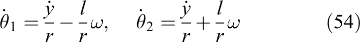
Hence, the scalar angular velocity of the platform is derived from equation (3) as

Let the distance between C and M be a, that between C and P being b. The velocity

Further, the planar twist

The differential forward kinematics model of the platform then being expressed as

with the 3 ×2 twist-shaping matrix

In order to derive the inverse kinematics model, equation (5) is expressed as

where the 2 × 2 matrix

Moreover
Hence

The inverse kinematics model of the platform can be readily obtained from equation (7), namely

Caster kinematics
As shown in Figure 1, the caster rolls on the ground at a rate
In this subsection, all vectors are considered three-dimensional. Let

while the scalar angular velocity of the bracket is

with ψ denoting the steering angle, between vectors
Moreover, the angular velocity of the caster can be readily expressed in the frame fixed to the bracket, namely

The velocity of the centre of the caster is

As shown in Figure 1, point P is the intersection of the vertical steering axis of the bracket with the platform plane. Let the height of the platform be h, the distance between point P and O 3 being d. The velocity of P can be calculated in two independent ways. First, P is regarded as a point on the platform, its velocity then being

On the other hand, if point P is regarded as a point of the bracket, then its velocity can be written as

Upon equating the right-hand sides of the above-mentioned two equations and simplifying them, we obtain a vector equation in the unactuated joint rates

Furthermore,

with the definitions given in the following

Letting

with the entries of the 2 × 2 matrix Θ given in the following


Apparently, the kinematics model of the DDMR consists of two main elements: the platform and the caster. The former relates the planar twist of the platform to the vector of actuated joint rates, while the joint rates of the caster are associated with those of the driving wheels in the latter. Since the casters do not constrain the mobility of the DDMR, the platform kinematics can be used to represent its planar motion in many applications. On the contrary, a thorough kinematics of the DDMR has to include the caster kinematics, in order to describe its spatial motion.
Multibody dynamics of DDMRs
Either the kinematics model or the dynamics model can be used for the navigation control architecture of mobile robots. If a DDMR is actuated only at the purely kinematics level, the reduced kinematics, only containing the platform, is sufficient for navigation control. However, if the dynamics model of the multibody DDMR is employed in the navigation control architecture, the kinematics of the caster, especially the steering angle, is required for the inverse-dynamics computation.
Navigation control architecture
Since electric motors are the common actuators in most rolling robots, the motor motion control system is to be analysed before the system is integrated into the navigation control architecture of mobile robots. A typical motion control system includes a feedback system with three cascaded loops, that is, the outer position loop, the intermediate velocity loop and the inner current loop, as shown in Figure 2. The position, velocity and current controllers can be physically implemented either in a controller or in a drive. A drive, also called an amplifier, is used to amplify low-power command signals generated by the controller to high-power voltage and current levels necessary to operate a motor. 25

Multi-loop motion control system.
Motion control systems have traditionally used a velocity sensor, for example, a tachometer, and a position sensor, for example, an encoder. Motor velocity and position are measured and fed back into the controller, while motor current is closed in a control loop by the drive. Nowadays, the boundary between the functions of a controller and a drive is becoming blur. Many off-the-shelf motor drives provide the complete control capability for all three loops, which implies that there are several optional control interfaces when a motion control system is integrated into the navigation control architecture of mobile robots.
A drive control and trajectory tracking system was proposed for a robotic wheelchair.
26
A more general navigation control architecture based on the kinematics model is shown in Figure 3. This is a multi-closed-loop cascaded feedback control system, including hardware, software and algorithm blocks. Path deviations are calculated by comparing the data coming from the path generator with that from the localization system. Path-tracking is used to eliminate these path deviations by controlling the twist
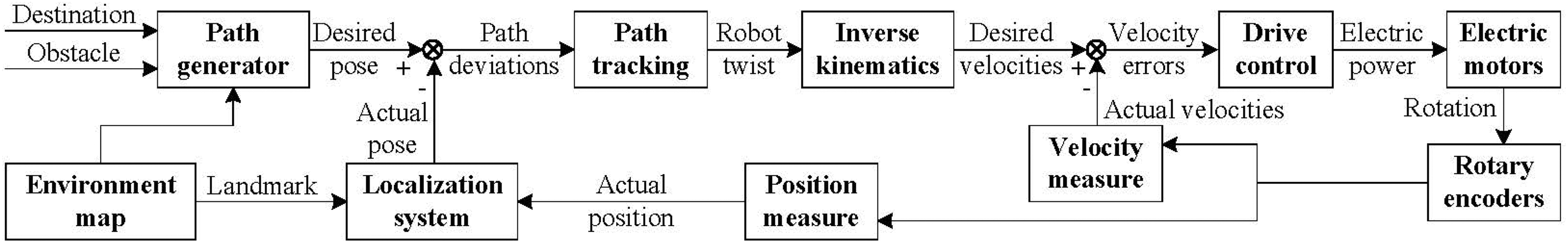
Kinematic navigation control architecture.
The reduced kinematics model only containing the platform can be effective in applications whereby the robot is lightweight. However, it is nearly impossible to ignore the effects of multibody dynamics for either heavy-duty robotic vehicles or for lightweight robots performing fast manoeuvres. Therefore, another solution is proposed for the navigation control architecture, as shown in Figure 4. This architecture includes an additional algorithm block for inverse dynamics, between inverse kinematics and drive control. Since a time-history of actuated joint rates can be obtained using the inverse kinematics while a mobile robot tracks the target path, actuated joint rates and their time derivatives are all known in the inverse dynamics of mobile robots, which generate the desired torques for the motors of the driving wheels. In this case, the motion control system only needs drives to close the current loop and to implement the torque feedback control. When the robot dynamics is integrated into the navigation control architecture, a multibody system model will be adopted, implying that each rigid body, including the caster and the bracket, should be taken into account. Furthermore, the inertia matrices and the terms of Coriolis and centrifugal forces of the caster and the bracket are both posture-dependent, associated with the steering angle, as discussed in the following.

Dynamic navigation control architecture.
Multibody dynamics model
First, we recall the generalized dynamics model derived from the Newton–Euler equations by means of the natural orthogonal complement for a mechanical system containing n rigid bodies 27

where

Moreover

and

where


with
Since the Newton–Euler formulation applies to multibody dynamics, we distinguish five rigid bodies composing the DDMR, as shown in Figure 1. These are the left actuated wheel, the right actuated wheel, the caster, the bracket carrying the caster and the platform. These bodies are labelled from 1 to 5, in the foregoing order. The 6 × 6 inertia dyads of the three wheels are denoted by


where, from equations (1), (6) and (11)
with
Upon first substituting equations (4) and (19) into equation (12), and then substituting equations (12) and (18) into equation (13), one obtains

and hence

with

Moreover

and hence

Substitution of equations (4) and (19) into equation (12) yields

with

Let point O
4 be the centre of mass of the bracket, lying in the middle of segment

Upon substituting equations (18) and (38) into equation (40),
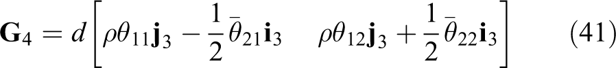
The 2 × 2 generalized inertia matrix

The coefficient matrix
Steering angle computation
In the navigation control architecture, path tracking can be a purely kinematics control technique without consideration of the effect of the caster. Only the platform twist
Angle ψ can be obtained in two ways. One is by means of an encoder installed on the vertical axis of each caster. In practice, however, commercial off-the-shelf casters do not have a mechanical interface for installing encoders. The common structure of caster products is shown in Figure 5. The bracket is connected with the plate by means of a thrust bearing, which allows the bracket to freely rotate with respect to the plate, about a vertical axis. The plate is then used to fix the caster assembly onto the robotic platform. It is apparent that commercial casters do not have a physically vertical shaft passing through the plate, so it is difficult to mount an encoder on the bracket.

Off-the-shelf caster structure.
Furthermore, if the mobile robot has more than one caster, especially for the purposes of enhancing the stability and load-carrying capacity of a heavy-duty robot, the motion measurement system tends to become complex and bulky. This may explain why the kinematics navigation control architecture is more popular in research and industrial practice – only requiring a simple platform kinematics model, and without the need of additional sensors for the casters. On the contrary, dynamics control requires not only an inverse dynamics model with extra computational cost for matrices
As shown in Figure 1, the steering angle ψ is the angle between axis Y attached to the platform and axis Y
3 attached to the bracket. Axis Y
3 is the direction of the velocity of point P on the vertical steering axis of the bracket, which coincides with the corresponding point on the platform. Since these two points have the same velocity, the velocity
Velocity computation based on compatibility
This problem can be handled by means of constraints on the velocity field of a rigid body. For a rigid body in planar motion, the velocity field is fully determined by the velocities of two points; the velocity of a third point can then be obtained according to the velocity-compatibility condition. By virtue of the body rigidity, the velocity components of two arbitrary points projected along the line joining them are equal

or, in a terser form

where the 2 × 2 matrix

with

Moreover

The inverse of

Upon substituting equation (47) into equation (43), one can readily solve for the velocity
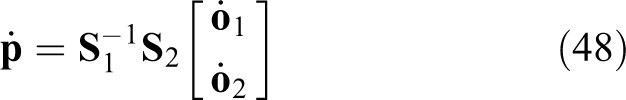
Finally, the velocity

Velocity computation based on twists
If the twist of a rigid body is known, the velocity of an arbitrary point of the body, given by its position vector, is readily computed by means of the velocity field provided by the twist. For the DDMR under study, the platform twist
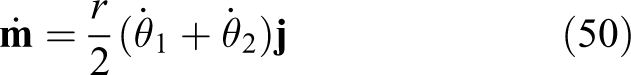
The velocity of point P can thus be expressed as

Substitution of equations (4) and (50) into equation (51) leads to the same result of equation (49). It is thus apparent that the computational method based on the twist is more convenient than that based on compatibility, since the computation of the inverse matrix is obviated for a rigid body undergoing planar motion.
Steering angle
As shown in Figure 1, since the steering angle ψ is that between the velocity

The steering angle ψ is thus uniquely determined from equation (52).
Simulation
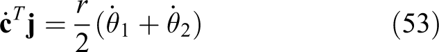
Simulation tests were conducted to verify the feasibility of the foregoing computational scheme for the steering angle, and further, to evaluate the significance of caster dynamics on the multibody modelling of a DDMR. The geometric parameters of the DDMR at hand are given in Table 1. In order to simplify the computation of the actuated joint rates, the scalar equations of the inverse kinematics of the platform are first derived. Both sides of equation (10) are dot-multiplied by
Geometric parameters.

The scalar equations of the inverse kinematics are readily derived by combining equations (4) and (53), namely
where the longitudinal speed is
Steering-angle computation
When the DDMR tracks a straight line, the two actuated joint rates are equal. The steering angle ψ remains zero in this trajectory, according to equation (52). Next, we consider the path tracking upon changing course, that is, when the path consists of two lines at a given angle, joined by a blending curve. Rather than circular arcs and ellipses, Lamé curves, named after their inventor, the French mathematician Gabriel Lamé (1795–1870), are used here to smooth the trajectory at the blending points, thus providing the full trajectory with G
2-continuity, meaning that position, tangent and curvature are all continuous along the path.
28
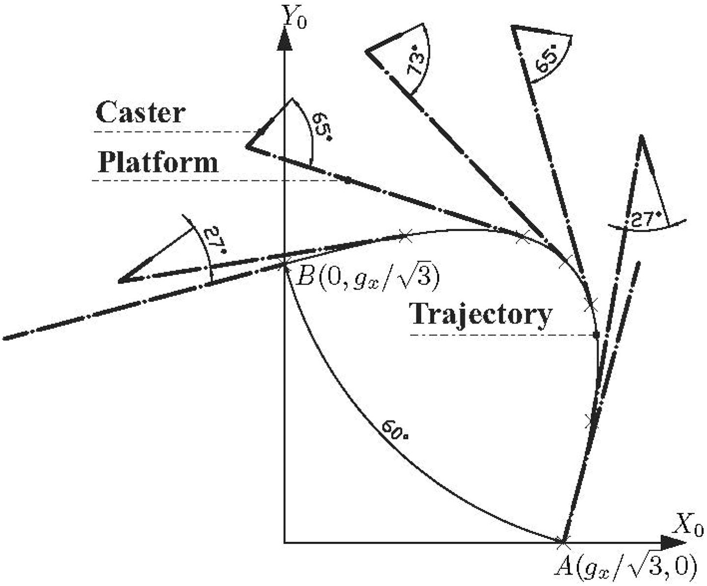
The third-order Lamé curve, the lowest order of this curve family with a variable curvature, is chosen as the target trajectory for the DDMR. This curve is defined in the inertial frame

where gx
= 1 m, gy
=1 m,
Suppose that the DDMR starts on a straight line and accelerates to a constant speed of 0.5 m s−1. Then, the DDMR enters this Lamé curve at point A(gx , 0), moves counterclockwise along this curved trajectory and departs from this curve at point B(0, gy ) to join the other line. When the DDMR travels on the Lamé curve, the steering angle of the caster begins to change from zero gradually, affected by the variable curvature κ

In order to simplify the computation of the curvature, the coordinates x and y are defined explicitly in terms of parameter φ as
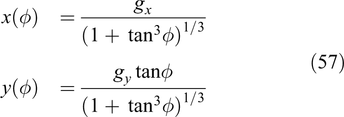
where ϕ is the orientation angle of the DDMR, measured with respect to axis X0 in the inertial frame
Upon substituting equation (57) into equation (56), we obtain

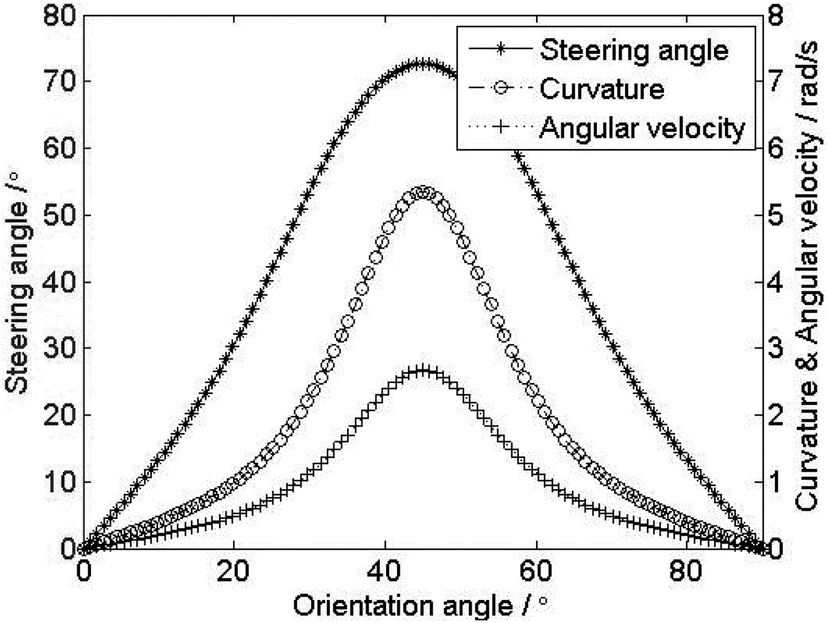
In Lamé curves, the curvature increases gradually from zero to a maximum, and then decreases to zero again, when the orientation angle ϕ changes from 0 to

Time histories of variables along the Lamé curve.
A set of poses of the robotic platform and the caster on typical points of the Lamé curve are depicted in Figure 7. The bold dashed lines, tangent to the curve at typical points, denote the platform heading direction. The bold solid lines connecting with the front end of the platform indicate the caster. The angle between the corresponding dashed line and the solid line is nothing but the steering angle. Since the turning motion of the caster is towed by the platform, the orientation change of the former lags behind that of the latter. The orientation difference between platform and caster, the origin of the steering angle, increases with the trajectory curvature synchronously.

Poses of the DDMR on the Lamé curve with the tangents at the inflection points making a right angle. DDMR: differential-driving mobile robot.

Matrix-element variation along the Lamé curve of Figure 7.
As mentioned earlier, the dynamics of the DDMR with casters is posture-dependent. Essentially, this dependence on the steering angle stems from the transformation matrix Θ, relating the unactuated joint rates
It is noteworthy that the Lamé curve is not limited to blending two lines at a right angle. In fact, any two lines at an arbitrary angle can be smoothly blended by means of Lamé curves, suitably shaped by affine transformation, for example, a stretched or squeezed Lamé curve in which its tangents at the inflection points make angles of 120° or 60°, for example, as shown in Figures 9 and 10, respectively. Apparently, a stretch deformation makes the curvature of the Lamé curve smaller at each point, while its squeezed counterpart makes it larger, as illustrated in Figures 6, 11 and 12. When the orientation angle ϕ becomes 45°, the curvature κ and the steering angle ψ reach their maximum values: 0.594 m−1 and 19.614° on the stretched Lamé curve and 5.345 m−1 and 72.683° on the squeezed Lamé curve, respectively. Hence, it can be concluded that the steering angle will change with the curvature of the trajectory that the DDMR tracks.

Poses of the DDMR on the stretched Lamé curve with the tangents at the inflection points making an angle of 120°. DDMR: differential-driving mobile robot.
Poses of the DDMR on the squeezed Lamé curve with the tangents at the inflection points making an angle of 60°. DDMR: differential-driving mobile robot.

Time-histories of variables along the Lamé curve of Figure 9.
Time-histories of variables along the Lamé curve of Figure 10.
Modelling-performance comparison
As explained earlier, the dynamic effects of casters are often neglected in the system modelling of DDMRs in the literature. Possible reasons include the following: (1) casters do not constrain the mobility of DDMRs and (2) the mass of a caster is relatively small when compared with that of the platform of the DDMR, so that its effects on the inertia of the whole system can be ignored in order to reduce the complexity of the robot model. However, to the authors’ knowledge, the research work providing a justification of the claim that the caster dynamics is negligible has not been reported. A performance comparison is conducted in this subsection to evaluate the dynamic effects of casters on the whole system model, by considering the generalized inertia matrix with and without the caster and its bracket.
As shown in Figure 1, the masses of the left actuated wheel, the right actuated wheel, the caster, the bracket and the platform are assumed as: m 1 = m 2 = m 3 = m 4 = 1 kg, m 5 = 30 kg, respectively. The geometric parameters are listed in Table 1. When the generalized inertia matrix is computed for the dynamics modelling of DDMRs, most previous methods do not consider the caster and its bracket, while our approach covers all five rigid bodies, namely
where
According to equation (42), since the inertia dyads
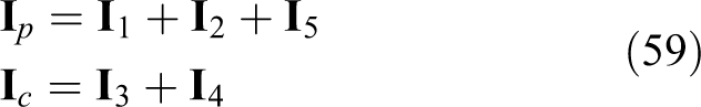
Simulation is conducted to test the variation of the generalized inertia
The inertia-matrix entries of the caster.
In order to evaluate the dynamic effects of the caster on the generalized inertia matrix quantitatively, still without relying on the specific geometric and inertial parameters, the ratio of the variable inertia caused by the caster to the constant inertia reported in the literature is plotted in Figure 14. In fact, this inertia ratio also implies the relatively computational error on the generalized inertia matrix incurred when the caster dynamics is neglected in the model of DDMRs.

The inertia ratio of the caster to others.
The inertia ratio for entry (1, 2) exhibits an extremely large variation range, with a maximum value of 76.4% when ψ = ±90°, and a minimum value of 26.5% when ψ = 0°. The amplitudes of the inertia ratio for entries (1, 1) and (2, 2) are also too large to be ignored. The former attains a maximum of 26.6% when ψ = −72° and a minimum of 17% when ψ = 18°, while the latter attains a maximum of 26.6% when ψ = 72° and a minimum of 17% when ψ = −18°. As shown in Figures 7, 9 and 10, the maximum steering angles of the DDMR travelling on the normal, stretched and squeezed Lamé curves are 47°, 20° and 73°, respectively. Taking the normal Lamé curve, for example, the relatively computational errors of the generalized inertia matrix reach 19.2% for the (1, 1) entry, 53% for the (1, 2) and (2, 1) entries, and, finally, 24.9% for entry (2, 2). The comparison results verify definitely that the dynamic effects of casters on the whole system model exceed the significance that was expected as usual, even if the mass of the caster only accounts for a small proportion in the total mass of a DDMR.
Finally, we summarize the foregoing simulation results: (1) the caster-wheel dynamics has a significant effect on the multibody modelling of a DDMR; (2) the steering angle is indispensable for the accurate dynamics model of the DDMR with casters; (3) the steering angle is readily calculated by means of the computational scheme proposed here, thereby obviating the need of dedicated encoders for casters; and (4) the steering angle is influenced by the trajectory curvature, which is addressed by means of a trajectory with a smooth curvature variation, thus easing the control task.
Conclusions
Given that many off-the-shelf motor drives are supplied with full control capability in the current, velocity and position loops, the DDMR model in the navigation control architecture can be either kinematic or dynamic. The former relates platform twist and joint rates in the velocity loop, while the latter associates joint rates with motor torques in the motor-current loop. For DDMRs with casters, a reduced model is sufficient for purely kinematic navigation control. However, the multibody system model is indispensable for dynamic navigation control of heavy-duty robotic vehicles in high-speed manoeuvres. In this case, the caster kinematics, especially the knowledge of the steering angle, is required to calculate the inertia matrix and the terms of Coriolis and centrifugal forces.
A thorough kinematics model and a multibody dynamics model, including the platform and all different wheels, are formulated for DDMRs. Computational schemes based on velocity compatibility and rigid body twists are proposed to estimate the steering angle without using dedicated encoders for casters. Lamé curves, with G 2-continuity, are chosen here as the blending curves for DDMR manoeuvres. Simulation results verify the feasibility of the computation technique and the significance of the caster dynamics. Since almost all current commercial mobile robots are not equipped with dedicated encoders for measuring the steering angle of casters, a customized DDMR prototype will be developed as an experimental platform, in which a dedicated encoder will be mounted on the specially designed vertical shaft of the caster, in order to further validate our approaches in the prototype.
Footnotes
Declaration of conflicting interests
The author(s) declared no potential conflicts of interest with respect to the research, authorship, and/or publication of this article.
Funding
The author(s) disclosed receipt of the following financial support for the research, authorship, and/or publication of this article: This work was supported by the Fundamental Research Funds for the Central Universities of China (NS2016050).