
Abstract
Due to the absence of mechanical contact, active magnetic bearing can be electrically controlled in an accuracy of a micrometer. This makes it a good choice to be used for robot manipulation in the micrometer scale, especially in environments that need to be very clean, for example, surgery or clean rooms. Moreover, it can be used in the applications that need high precision micromotion such as semiconductor wafers manipulation. Despite all these benefits, there are few studies that have investigated the application of active magnetic bearing in the robotics field in spotless environments for micromotion applications. This article proposes a new novel six-degree of freedom two-link manipulator using two contactless joints with active magnetic bearing. The key design aspects of the proposed manipulator are presented. The proposed manipulator is designed using finite element method. Each joint roll angle is controlled using a PID-based feedback linearization controller, while a state feedback controller with integral term is used for controlling the active magnetic bearing five-degree of freedom. The stability analysis of the system, under the proposed controller, is carried out. The robustness of the controllers is tested against end effector payload variations. The results demonstrate that the proposed two-link manipulator is feasible and valid for the applications in spotless environments that need high precision accuracy micromotion control. These significant findings have indicated the feasibility of implementing this proposed manipulator in practice and open the door for developing other types of robots with complete contactless joints using active magnetic bearing.
Introduction
Active magnetic bearing (AMB) uses electromagnetic forces to levitate an object, typically a rotor without friction. It controls the rotor position with an accuracy of a micrometer. 1 AMB possess several remarkable advantages compared to conventional bearing such as lubrication-free operation, extended life, controllable bearing dynamic properties, and frictionless operation. 2 Thus, AMB is used in many industrial applications such as high-speed rotating equipment, machine tool, machining spindle, vacuum pumps or compressors, bearingless motors, artificial heart pumps and flywheel-based energy-storage devices. 3 –5
Due to the absence of friction and lubrication, AMB can be used in spotless environments like clean rooms, surgery rooms, or vacuum chambers. Robots in these environments must be free of any dust or oil generation sources. Therefore, AMB is preferable to be used for the joints of that kind of robots. Tasks in these environments such as silicon wafers transfer for the electronic manufacturing need to move the manipulator end effector with high precision positioning control.
For the past decades, an apparent clear trend in using AMB in robotics could be noticed. In Higuchi et al., 1 an experimental study of using AMB in robot joints has been made. A prototype of clean room parallel robot consists of two-degree of freedom (2-DOF) and five joints was constructed. However, this study does not lead to a completely contactless joints robot. In Tezuka et al., 6 a novel magnetically levitated motor consists of a five controlled DOFs was investigated theoretically using AMB. A novel contactless 6-DOF active robotic joint using AMB is presented in Selmy et al. 7 and developed in Selmy et al. 8
Some research has been done to investigate the use of robots in a clean environment for high positioning accuracy applications. For instance, a clean compatible PA10-6C/7C robotic arm is used for semiconductor wafer handling with milli-scale positioning accuracy. 9 However, their joints do not have a magnetic bearing. Koichi Matsuda and Shinya Kijimoto 10 treat a disturbance cancellation problem for minimizing the effects of reaction forces on position accuracy of a clean room robot applied with magnetic bearings. However, the developed robot moves with only 3-DOF to transfer a wafer among processing chambers.
A new design of a force-controlled end effector for robotic polishing tasks is presented in Mohammad et al. 11 The end effector has a polishing head with a linear coil actuator to provide tool compliance using thrust bearing. However, the polishing head of the end effector is driven by geared AC motor and the bearing is of contact type. Other studies of controlling robot arm movement in one-axis direction and mobile robot arm position control are investigated in the study by Božek et al., 12 Turygin et al. 13 , and Lozhkin et al. 14
In a previous work, a 6-DOF robotic joint with AMB was designed in the study by Selmy et al. 7 Despite the good performance of that joint, it suffers from limited workspace of the end effector movement. Thus, to overcome these limitations, a new two-link manipulator with two novel contactless 6-DOF joints is proposed and developed in this article. This system opens new applications area for AMB in robotics, for example, robots used in clean environments such as clean and surgery rooms, self-reconfiguration robots, robots with selective compliance, industrial robots for laser cutting or arc welding, and space robots.
The main contributions of this article are as follow: A new novel two-link manipulator, which utilizes two novel contactless 6-DOF joints is designed. A controller design to track the desired end effector 6-DOF trajectory for micromotion, with precise stability analysis, is carried out.
The rest of this article is organized as follows. In section “Description and design of the proposed system,” the description and design of the proposed system are presented. The mathematical model including the dynamics of the motor and AMB for each joint are derived and discussed in section “System dynamic model”. The forward and inverse kinematics analysis of the novel system is analyzed in details in section “Kinematics”. Proper design of the controllers for each joint is developed and stability analysis of the controller is carried out in section “Control design”. In section “Simulation study”, the performance of the proposed manipulator is evaluated and its effectiveness in micromotion scale applications is demonstrated. Finally, the conclusions are presented in section “Conclusion”.
Description and design of the proposed system
In this section, the two-link manipulator with the two contactless active joints using AMB is described and designed in detail.
System description
A schematic diagram of the proposed system is shown in Figure 1. This system consists of two contactless 6-DOF joints, each one has a frameless brushless DC (BLDC) motor, two radial AMB, one axial AMB, a sensor for measuring the motor shaft roll angle, position sensors to measure the AMBs air gap deviations and the controllers.

System schematic diagram.
The two-link manipulator system block diagram is shown in Figure 2. The actual end effector position and orientation are computed using the data from each of the two contactless joints motor roll angles sensors and the AMB air gap deviations measurement sensors. The controllers minimize the errors between these obtained measurements and the desired ones by sending the suitable control signals to the electromagnetic coils of AMB and motors stators windings of each joint. This makes the AMB actuating magnets produce suitable electromagnetic forces and the motors produce suitable torques to maintain the end effector at its desired position and orientation.
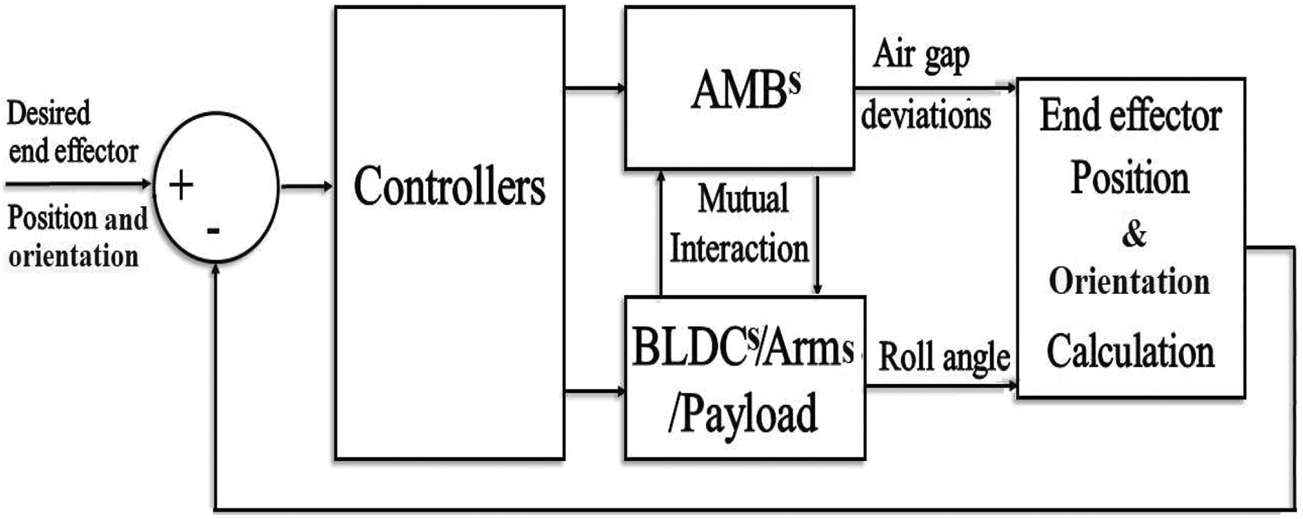
System block diagram.
System design
Figure 3 shows the design process flowchart of the proposed system. First, the closest joint to the end effector, joint 2, is considered in the design process, then the other joint, joint 1, is designed.

Design process flowchart.
Load torque calculation
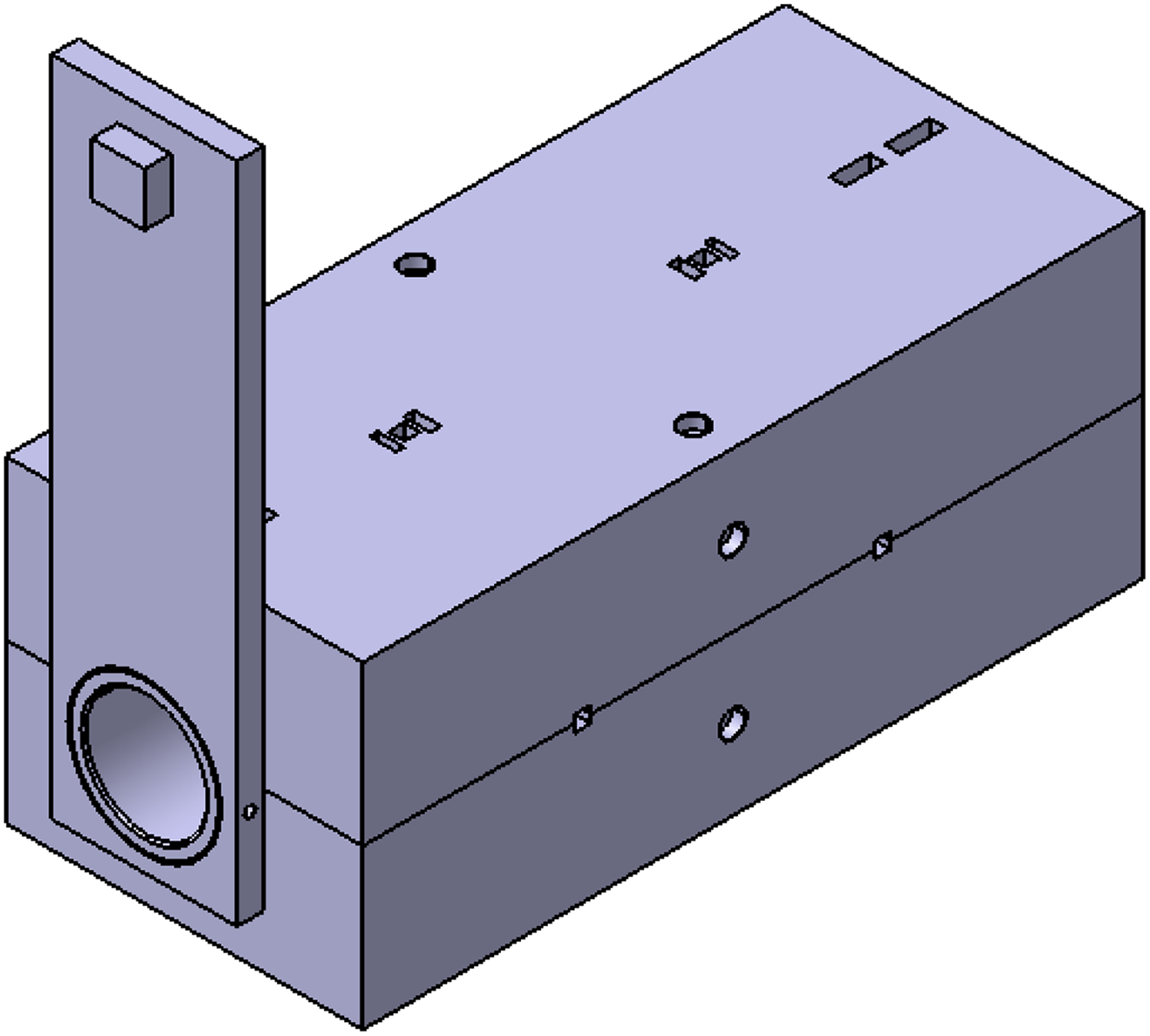
Considering the manipulator end effector will pick a payload mp = 0.1 Kg average mass attached to an arm with 250 × 70 × 10 mm3 dimension, ma = 1.15 Kg mass, and 0.125 m C.G. Location. Figure 4 shows the load including arm and payload. This arm will be attach to the motor shaft.

Joint 2 load (arm and payload).
The maximum load Torque,

As a result, the maximum load torque equals 1.2 Nm.
Selection of motor
According to the previous mentioned calculated load torque, a frameless brushless direct drive, 145STK 1M, Alxion BLDC motor 15 is selected. Motor main features are continuous torque of 8 Nm, a speed of 1500 r/min, rotor diameter of 56 mm, and rotor length of 59 mm. According to the rotor diameter and rotor length, the shaft length is calculated and found to be = 310 mm.
AMB electromechanical design
In order to facilitate the design of the electromagnetic coils of the radial AMBs, the total weight to be carried by the two radial AMBs of joint 2 is calculated and it is found to be 5 Kg. Then, the total force carried by the two radial bearings with 20% factor of safety is 58.8 N.
Considering one of the two radial AMBs (the left radial AMB), then the upper electromagnetic force

Using equation (2) for
A conventional eight-pole radial AMB which has the geometry shown in Figure 5 is chosen.The radial AMB design is developed to find the dimensions of the magnetic actuator based on the maximum load capacity, a number of poles and air gap length. 16

Conventional eight-pole radial AMB. AMB: active magnetic bearing.
The flowchart in Figure 6 illustrates the design procedure of each eight-pole radial AMB. First, specify the maximum bearing force, rotor radius, the bearing number of poles, pole angle and the air gap length as an initial step. Then, the design procedure is followed and equations (4) to (12) are used to obtain the dimensions of each of the radial magnetic actuator 16


where

Design procedure of eight pole radial AMB. AMB: active magnetic bearing.
Table 1 shows the magnetic actuator parameters and the calculated radial AMB dimensions based on the total weight, the dimension of the shaft, and the actuator geometry.
Joint 2 radial AMB dimensions.

AMB: active magnetic bearing.
In order to meet the required thrust in the axial direction of joint 2, an axial AMB is designed as shown in Figure 7. The axial AMB consists of the housing parts wound by coils, the disk part located between both of the housing parts. The magnetic thrust force can be expressed by following equation 17,18

where S is the flux area in the air gap,

Axial AMB structure. AMB: active magnetic bearing.
Joint 2 axial AMB dimensions.

AMB: active magnetic bearing.
The same previous steps (from “Load torque calculation”, “Selection of motor”, and “AMB electromechanical design” sections) of designing the radial and axial AMBs of joint 2 are repeated for joint 1 design. The load of joint 1 is the joint arm as well as the total weight of joint 2 including the BLDC motor, radial AMB, axial AMB, Sensors, arm, payload, and the joint casing. Therefore, The maximum load torque,
Joint 1 radial AMB dimensions.

AMB: active magnetic bearing.
Joint 1 axial AMB dimensions.

AMB: active magnetic bearing.
System CAD model
The system is drawn using CATIA. 19 Figure 8 shows the CAD model of joint 2 while Figure 9 shows joint 2 CAD model details. Figure 10 shows the CAD model of the all system and Figure 11 shows the details of joint 1. In this system, the robot arms with the payloads as well as the rotating parts of the axial magnetic bearing and the roll angle sensors are fixed to the shafts using set screws.
Architecture of joint 2.

CAD details of joint 2.

Architecture of the all system.

CAD details of joint 1.
System finite element analysis
The stress and deflection of the system are studied using finite element method, and the results will be illustrated in “Simulation study” section.
Checking system safety
In this step, calculated stress and deflection values are compared with the maximum allowable stress of steel and the length of the air gap.
System dynamic model
In this section, a multiple-input multiple-output (MIMO) mathematical model of each joint of the system is developed including detailed models for the BLDC motor and the radial and axial AMBs. Moreover, the model of AMB is linearized around the equilibrium point.
BLDC motor dynamic model
Frameless brushless direct drive DC motor is used in this system. This type of motors has the advantages of having no contact part, no gearbox, and compatibility with AMB. The stator windings equations in terms of motor electrical constants for three-phase, star-connected BLDC motor 20 are


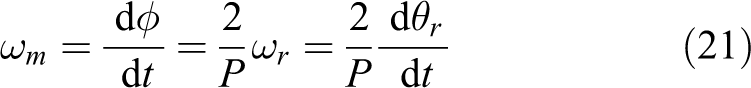
where
Figure 12 shows the block diagram of the BLDC motor control system. The joint roll angle is measured and compared with that of the desired trajectory
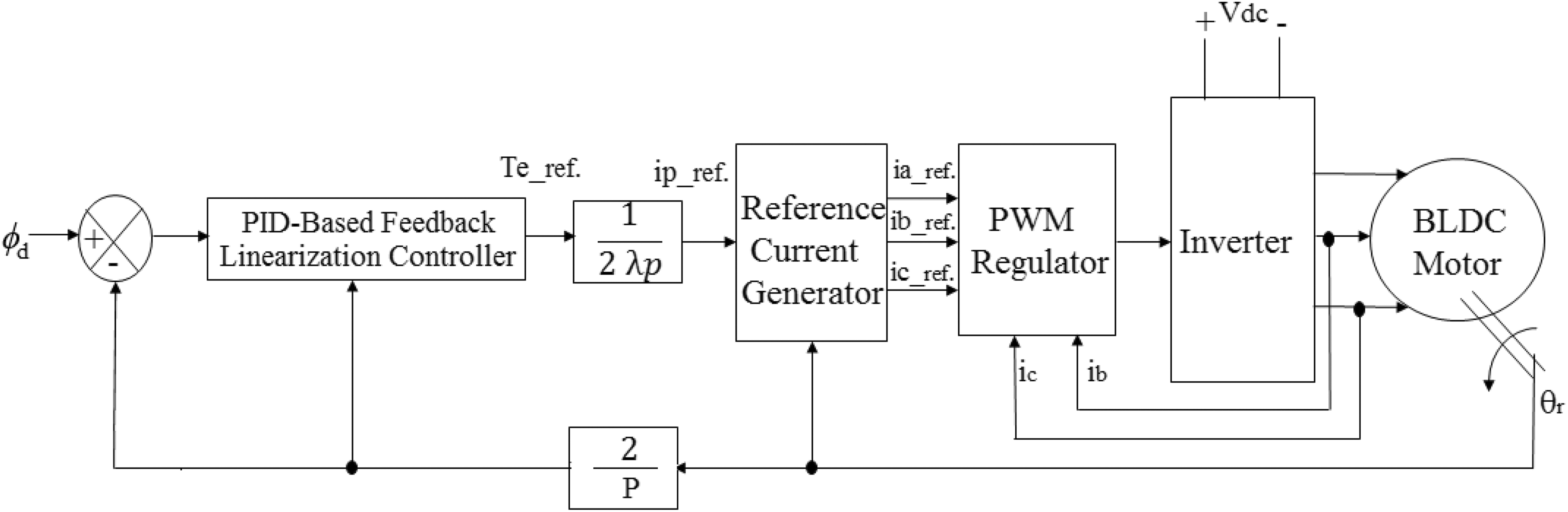
BLDC motor model block diagram. BLDC: brushless DC.
AMB dynamic model
Dynamic equations of motion
Figure 13 shows an AMB of horizontal shaft type, it consists of two radial AMBs and one axial AMB. Both of the radial AMBs control the horizontal, vertical, pitch, and yaw motions. The axial AMB controls the axial linear motion. The dynamic equations of this system are given as follows 21,22

Horizontal shaft AMB diagram. AMB: active magnetic bearing.
Axial direction:
linear motion

Radial direction:
Horizontal linear motion

Vertical linear motion

Pitching rotational motion

Yawing rotational motion

Electromagnetic coil voltage equation
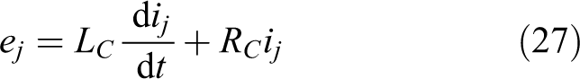
where
The centrifugal force in the vertical direction is given as follows

The centrifugal force in the horizontal direction is given as follows

The forces


where
The air gap displacement, gj is expressed as follow:

where
State variable representation
The state variable representation of radial AMB is given in “Appendix 1: State space representation of AMB.” The 4-DOF radial motion is represented by a MIMO nonlinear system with 16 states, 8 inputs (electromagnetic coil voltages), and 4 outputs (air gap deviations). The 1-DOF axial motion is represented by a multi input single output nonlinear system with 4 states, 2 inputs (electromagnetic coil voltages), and 1 outputs (air gap deviation). The 4-DOF system is linearized around the equilibrium point and the following linearized model is obtained, where


In a similar way, the state variable representation and the linearized model for the axial linear motion is obtained and are given in the same previous mentioned appendices.
Kinematics
In Figure 14, the end effector position, and orientation of the two-link manipulator are controlled by controlling the joint angle and the air gap lengths of the AMBs in radial and axial directions of the two contactless joints.

Frames location on the proposed robotic joint.
The relation between the end effector position; translation (xe, ye, ze) and rotation (
Forward kinematics
The reference frame
Frame
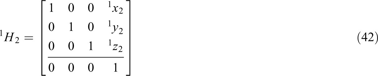
The relation between frames

where
The relation between frames
Knowing the air gap deviations of the radial AMBs of joint 2, (
The rotation matrix of frame


Then, the relation between frames

where

Also, the relation between frames
where
The relation between frames
Knowing the air gap deviations of the radial AMBs of joint 1, (
The rotation matrix of frame


Then, the relation between frames

where

Finally, using equations (41) and (46), the relation between frames

Thus, if the sensors data of the roll angle and the air gap deviations of the AMBs for each joint of the manipulator are given, then the end effector position and orientation can be obtained using forward kinematics equations.
Inverse kinematics
If the end effector has to move for a certain task, then its target position and orientation (xe, ye, ze,

Afterward, for a chosen
Then, from equation (46) we get
Control design
Control objectives
In order to control the end effector position, each joint roll angle is controlled using a PID-based feedback linearization method. In addition, the air gap lengths of the AMBs in the horizontal, vertical, and axial directions are controlled to be at the desired values using a state feedback controller with integral term.
PID-based feedback linearization
For the PID-based feedback linearization controller, 24 equations (19) and (20) are used to get the following control input that cancels out the nonlinearities

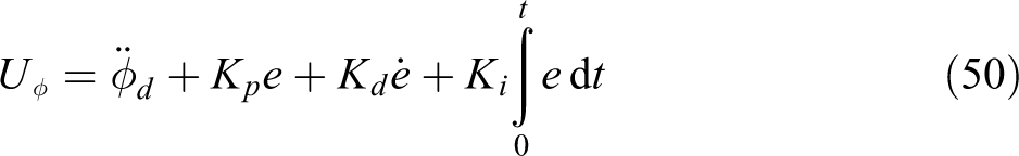
where
The integral term is added to ensure robustness of the controller for payload variation. The objective of the controller is to minimize the error, e =
State feedback controller
The five air gap deviations of the two radial AMBs, of each joint, in radial and axial directions are controlled using state feedback controllers with integral term. The optimal state feedback gains are calculated by knowing all the states of the system using Linear-Quadratic Regulator (LQR). 25
In particular, for a certain required position and orientation of the end effector, the controllers obtain the actual air gap lengths of the 5-DOF AMBs and the actual roll angle from the sensors of each joint. Then, the controllers minimize the error between these values and the desired ones to achieve the required pose of the end effector.
Stability analysis
To simplify the analysis, let us study the stability of linearized 1-DOF axial motion, given in “Axial motion” section in Appendix 2. Using Routh Hurwitz stability criterion, 26 the necessary and sufficient conditions for stability are


where


Moreover, equations (53) and (54) are solved using the method explained in Al-Salem et al.
27
to obtain
From the above equations, and as a result, we found that the stability is guaranteed when the following conditions are satisfied


where
Simulation study
System finite element analysis
A study of the system is carried by CATIA design software using radial AMBs for joint 2 and joint 1 whose parameters are given in Tables 5 and 6 in respective order. This study is developed at the case where a robot arm is in a vertical position and at the worst loading condition when the robot arm is at a horizontal position. The system is studied under its weight effect as a result of the low speed of the robot joint.
Joint 2 AMB parameters.

AMB: active magnetic bearing.
Joint 1 AMB parameters.

AMB: active magnetic bearing.
Figure 15 shows the stress analysis of the system for a vertical position robot arm, and the maximum stress is 0.273 MPa. Figure 16 shows the deformation analysis of the system in the same case, and the maximum deformation is 0.331 . Figure 17 shows the stress analysis of the system at worst case, and the maximum stress is 0.557 MPa. Figure 18 shows the deformation analysis of the system in the same case, and the maximum deformation is 1.2 µm.

System stress analysis at vertical position.

System deformation analysis at vertical position.
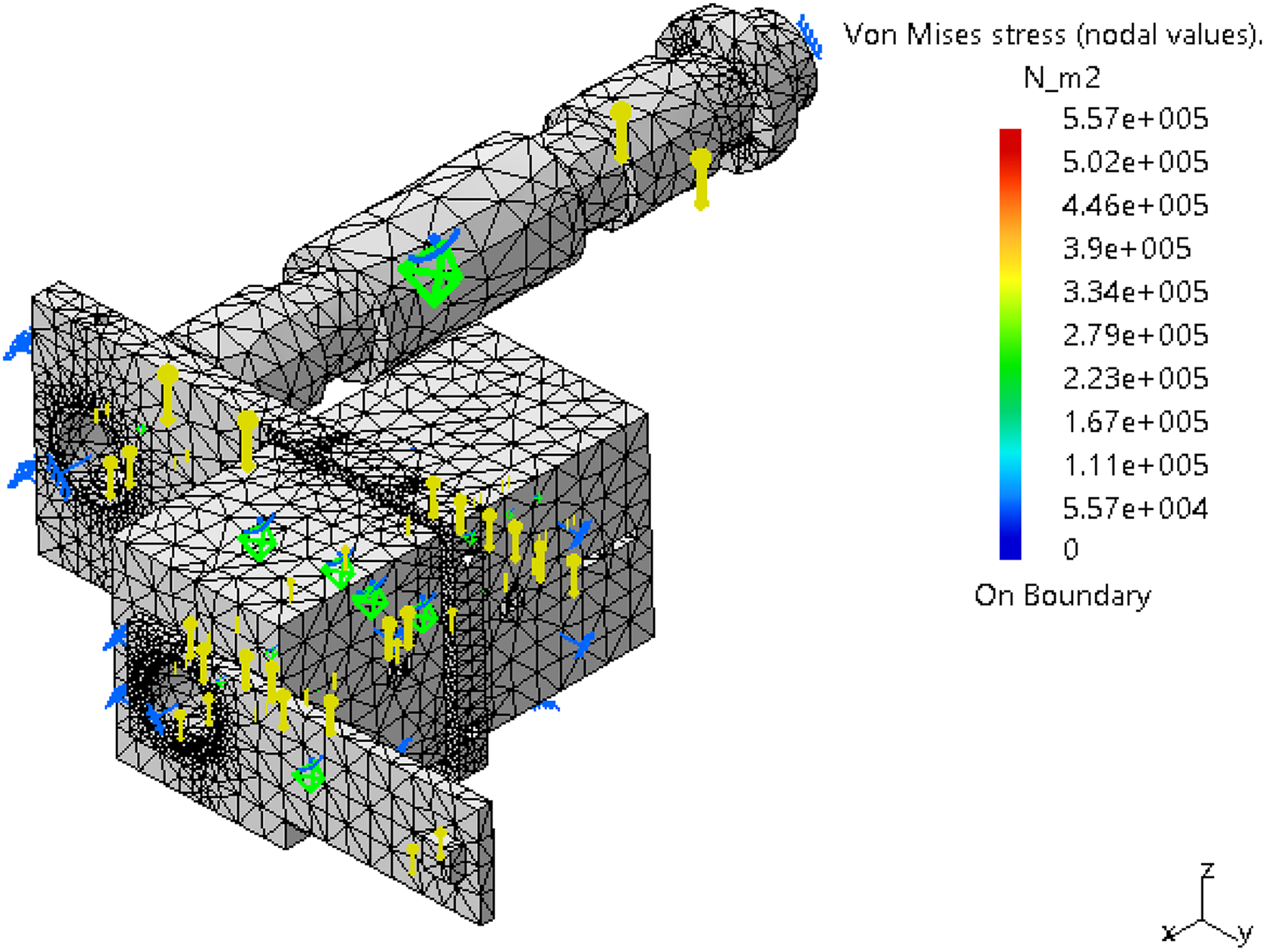
System stress analysis at horizontal position.

System deformation analysis at horizontal position.
The above finite element study proves that the obtained value of stress is safe compared with the allowable stress value of steel, and the obtained value of displacement is much less than the air gap length which is 1 mm.
System simulation analysis
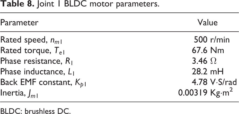
The BLDC motor parameters are given in Table 7 for joint 2 and Table 8 for joint 1. The system and its controllers represented by equations (14) to (50) are all simulated using MATLAB/Simulink. 28
Joint 2 BLDC motor parameters.

BLDC: brushless DC.
Joint 1 BLDC motor parameters.
BLDC: brushless DC.
In order to control the end effector position and orientation of the proposed two-link manipulator to be, for example, at (xe, ye, ze) = (−250 µm, 100 µm, −150 µm) and (
Thus, for the above required position and orientation of the end effector, (
The controller then uses these obtained desired values of joint angles and the air gap deviations of the radial and axial motions to achieve the desired pose of the end effector. The results of the end effector position and orientation at no payload and for payload 1 of 0.1 kg and payload 2 of 0.2 kg are shown in Figures 19 to 24.

End effector roll angle,
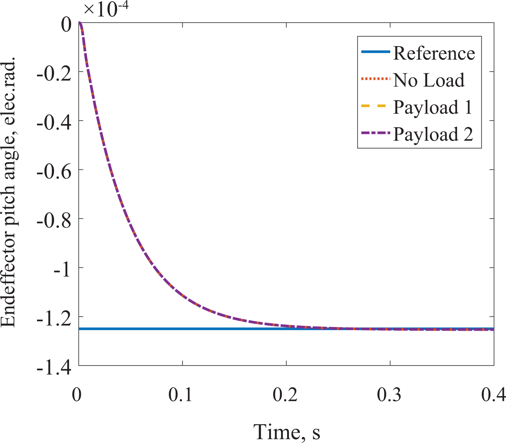
End effector pitch angle,

End effector yaw angle,

End effector axial motion, xe.

End effector horizontal motion, ye.

End effector vertical motion, ze.
Results and discussion
It is noticed that the obtained figures show a slightly and acceptable change between the reference and actual values at the different values of payloads. Moreover, it is possible to recognize that the performance of the proposed manipulator is acceptable and the effectiveness of it in micromotion scale applications is achieved.
Conclusion
In this article, a two-link manipulator with two novel contactless 6-DOF joints is proposed. Description and design of the presented system are introduced. The radial and axial AMBs of each joint are designed in details. The stress and deflection of the system are calculated using FEA method and they are safe with respect to the maximum allowable steel stress and the air gap length. Mathematical modeling and system kinematics are carried out. For each joint, PID-based feedback linearization controller is designed to control the joint roll angle and a state feedback controller with an integral term is designed for controlling the AMB air gap lengths. Stability of the controller is analyzed. The system with designed controllers has good performance and valid even if the payload is changed. Simulation results enlighten the feasibility of the proposed system and the efficiency of the end effector micromotion control. This proposed type of manipulator opens new application area for robotics. Such applications are clean and surgery rooms used in clean environments, self-reconfiguration robots, robots with selective compliance, industrial robots for laser cutting or arc welding, and space robots. As a future work, the proposed manipulator system will be tested experimentally.
Footnotes
Author’s note
Mohamed Selmy on leave: Faculty of Engineering at Shoubra, Benha University, Banha, Egypt; Mohamed Fanni on leave: Prod. Eng. Mechanical Design Dept., Mansoura University, Mansoura, Egypt; and Abdelfatah M Mohamed on leave: Electrical Engineering Department, Faculty of Engineering, Asyut, Egypt.
Acknowledgments
The first author is supported by a scholarship from the Ministry of Higher Education, Government of Egypt which is gratefully acknowledged.
Declaration of conflicting interests
The author(s) declared no potential conflicts of interest with respect to the research, authorship, and/or publication of this article.
Funding
The author(s) received no financial support for the research, authorship, and/or publication of this article.