High-speed pick-and-place parallel manipulators have attracted considerable academic and industrial attention because of their numerous commercial applications. The X4 parallel robot was recently presented at Tsinghua University. This robot is a four-degree-of-freedom spatial parallel manipulator that consists of high-speed closed kinematic chains. Each of its limbs comprises an active pendulum and a passive parallelogram, which are connected to the end effector with other revolute joints. Kinematic issues of the X4 parallel robot, such as degree of freedom analysis, inverse kinematics, and singularity locus, are investigated in this study. Recursive matrix relations of kinematics are established, and expressions that determine the position, velocity, and acceleration of each robot element are developed. Finally, kinematic simulations of actuators and passive joints are conducted. The analysis and modeling methods illustrated in this study can be further applied to the kinematics research of other parallel mechanisms.
Parallel robots possess specific characteristics, such as improved structural rigidity, higher accuracy, and better dynamic capacity, compared with traditional serial robots.1,2 Parallel robots are a significant complementary to the traditional serial robot and are widely adopted in the industrial field. High-speed pick-and-place parallel robots, such as Delta,3,4 H4,5 Diamond,6 and Par4,7 have been used in large-scale commercial applications and become frontiers of parallel robots.
A novel high-speed pick-and-place parallel robot called X48 has been proposed by researchers at Tsinghua University. The inputs of the robot consist of four active revolute joints. Each limb comprises an active pendulum and a passive parallelogram and connects to the end effector through the other revolute joint, as shown in Figure 1. The X4 robot differs from previous high-speed pick-and-place parallel robots.8 This robot releases a rotational degree of freedom (DOF) with a single platform. Four bars are connected end to end by four spherical joints that form the planar parallelogram. The symmetric X4 parallel robot, which is composed of four identical limbs and a simple end effector, shows advantages in manufacturing, cost, and reliability. Each limb is driven by a servomotor and a planetary gear reducer. The actuators of the X4 parallel manipulator are all in the fixed base, the limbs are made of carbon fiber, and the end effector is made of aluminum alloy that was designed to be lightweight to increase moving speed. The inertia of the moving parts of the X4 parallel robot is reduced, thereby offering the advantages of high speed and acceleration. Due to the unique connection of the end effector by four revolute joints, its translation is permanently accompanied by a supplementary rotation about a vertical axis, comparatively with the translational Delta parallel robot.
Three-dimensional model of the X4 parallel robot.
The kinematic analysis of the parallel robot, which involves DOF, singularity, and the motion mapping between the joints and the end effector, is the basis of the performance evaluation and motion control. During the last three decades, considerable effort has been devoted to this topic. DOF analysis is the first step to innovating and verifying the proposed parallel robot. Although the traditional Grübler–Kutzbach criterion plays a considerable role in the DOF calculation of planar mechanisms, it fails to indicate the DOFs of some spatial parallel mechanisms. Freudenstein and Alizade,9 Hunt,10 Phillips,11 and Marghitu and Crocker12 introduced the methods of conducting the DOF analysis of parallel mechanisms. However, their methods are valid only under certain circumstances with limited versatility. Huang et al.13,14 and Kong and Gosselin15 introduced screw theory to find a universal manner of analyzing the DOFs of parallel mechanisms. They calculated the DOF using the concept of kinematic and constraint screw systems. Zhao et al.16,17 investigated the DOFs and the singularity of spatial parallel mechanisms by parsing the expressions of kinematic and constraint screw systems. The approach based on screw theory is distinct in physical meaning and mathematical expressions, illustrating the DOF number and the available movements of the end effector, which are adopted in the present study.
Inverse kinematics is the foundation of motion control for parallel robots. Generally, approaches for the kinematics of high-speed parallel robots can be classified into three categories, namely, the vector method, the recursive matrix method, and the screw theory. The inverse kinematic models of the Diamond,18 Delta,19 and H420 were deduced using the vector method. In recent years, screw theory has been applied for the analysis of the kinematic model of parallel robots.21,22 However, the recursive matrix method23,24 is the most efficient manner of obtaining the position, velocity, and acceleration of all the elements and is thus used in the present study to establish the kinematic model of the X4 robot.
The remainder of this article is organized as follows. In the next section, the geometrical model and coordinate systems of the X4 parallel manipulator are established. Moreover, DOF analysis using screw theory is conducted in detail. In “Kinematic and singularity analysis” section, kinematic equations and Jacobian matrices of the X4 parallel manipulator are deduced using the recursive matrix method. Singularities of the manipulator are discussed. “Simulation” section conducts a numerical simulation using the established kinematic model. Finally, the conclusions of this study are presented.
Geometrical modeling and DOF analysis
The kinematic model of the X4 parallel robot is shown in Figure 2. Four revolute joints marked as A1, B1, C1, and D1 are symmetrically located in a circle with a radius of l0. A fixed base frame {OX0Y0Z0} is established at the center of the base. A local coordinate system {GXGYGZG} is established at the center G of the end effector and fixed with the end effector. The end effector initially begins to move from a central configuration where the center G of the end effector is located on the Z0 axis at a distance of OG = h, and the two frames are parallel to each other. The parallelogram in the X4 robot is connected by spherical joints, which can be simplified as universal joints in the kinematic analysis. The rotation of the horizontal bar of the parallelogram can be modeled by the revolute joint at its center. Description of important notations used in the modeling and analysis are listed in Appendix I.
Kinematic model of the X4 parallel robot.
As shown in Figure 2, the joint distribution angles in the base and the end effector are defined as follows. Angles αA, αB, αC, and αD are measured from the fixed X0 axis to the lines that connect the center O and the actuated revolute joints A1, B1, C1, and D1, and and . Angles ξA, ξB, ξC, and ξD are considered in the plane of the end effector from the XG axis to the lines that connect the center G and revolute joints A6, B6, C6, and D6, and and . Constant angles αC, αD, ξC, and ξD are measured using negative values because the architectures of the base and the end effector are symmetrical.
Limb A is selected as the representative of these four limbs due to its symmetrical distribution and identical limb structure. The kinematic model of limb A is illustrated in Figure 3. Eight revolute joints exist in the limb, which is labeled as Ai, and a candidate frame is connected to each revolute joint. The pendulum (A1A2 = l1) is the driving rod, which rotates around -fixed axis with angle , angular velocity , and angular acceleration . The center of the horizontal bar A3A7 (A3A7 = l2) in the parallelogram, which is connected to the frame , is denoted by A2. The horizontal bar has a relative rotation around the horizontal axis with angle , angular velocity , and angular acceleration . Two identical and parallel bars, namely, A3A4 and A7A8, rotate around parallel axes and , respectively, with angle . The length of these two parallel bars is l3. The four-bar parallelogram is closed by element A4A8 (A4A8 = l2), and is identical to . This element rotates around the axis with a relative angle of . Joints A5 and A6 are connected at the center of A4A8 and located at the end effector circle with a radius r (where ). Joint A5 has a relative rotation around the horizontal axis with relative angular velocity and angular acceleration . The end effector can rotate around the vertical axis with angular velocity and acceleration and , respectively.
Kinematic model and notations of leg A.
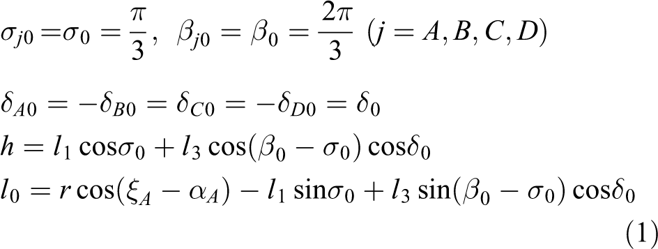
At the initial configuration, the end effector stays in the center of the workspace without any rotation, and coordinate systems {GXGYGZG} and {OX0Y0Z0} are parallel to each other, whereas Z0 and ZG axes are collinear. All pendulums begin from the central configuration with the same initial inclination angle σ0. Angle βA denotes the relative inclination of the four-bar parallelogram A3A4A8A7, which is the angle of the line of A1A2 and the axis. δA denotes the inclination angle of the parallel bars A3A4 and A7A8, which are defined by the line of A2A5 to the axis. Then, the initial configuration can be concluded as
The following equations hold
The DOF number of the X4 robot is derived on the basis of screw theory. A coordinate system is established at A2 to simplify vector expressions since the screw theory is independent of the reference system. The Y′ axis is along the direction of A2A7, and the Z′ axis lies in the parallelogram plane and is perpendicular to A3A7. Finally, the X′ axis is perpendicular to the parallelogram plane. The kinematic screw systems of limb A are expressed in the established coordinate system .
Eight twists (), which are all rotational, exist in limb A. Assuming that the unit rotational motion vector of $i is ωi and the position vector of the rotation center is , then each twist expressed by Plücker coordinates can be written as
The twist screw system cannot be directly obtained by a congregation of the eight twists due to the parallelogram structure in the$ limb. The parallelogram is equivalent to a generalized translational pair, and its motion can be denoted as
where represents the translational motion of bar A4A8 relative to A3A7. Then, the twist system of limb A can be written as
and
where . With the substitution of the corresponding expressions into equation (5), the kinematic screw system of limb A can be derived. Five screws in are linearly independent, and only one reciprocal screw exists with respect to , which can be expressed as
The aforementioned equations indicate that limb A exerts only one constraint couple to the end effector. The expression of in the global coordinate system {OX0Y0Z0} can be derived by the transformation matrix. The transformation matrix of the local coordinate system relative to the global coordinate system {OX0Y0Z0} can be deduced as
Then, the expression of in the global coordinate system {OX0Y0Z0} can be obtained as
where and .
Considering the symmetric structure of the X4 parallel robot, obtaining constraint torques of the three other legs is easy and the results can be expressed as follows
is collinear with , and is collinear with . Therefore, only two independent components exist in $r, and the constraint screw system of the X4 robot can be summarized as
Four twists can be derived according to the reciprocity theorem, which indicates four independent motions of the end effector as
where represents the rotation around the Z0 axis, and , , and represent translations along three orthogonal axes, respectively. Accordingly, the end effector of the X4 robot possesses four DOFs and can realize the typical SCARA motion required in sorting conditions.
Continuous judgment on the DOFs of the robot is necessary. An analysis of the five twists in shows that the collinearity of the screws can happen only among $1, $2, and $5. If , then $5 is collinear with $2. If ( or ), then only two screws of $1, $2, and $5 are independent. Both conditions cause a rank reduction of and increase the number of constraint screws, thereby reducing the DOF of the robot. When , the parallelograms coincide with a straight line, which cannot occur in practice. When , the active rod A1A2 coincides with the plane of the parallelogram. This phenomenon is a configuration that makes the robot singular and causes the end effector to reach the boundary of the workspace. In addition to the two cases, the five twists are independent of one another, and the constraint screw system of the robot is always the same as that in equation (11) regardless of the positions. Therefore, the DOF of the robot is continuous and always equals four.
Kinematic and singularity analysis
In studies regarding the kinematics of parallel manipulators, matrix equations that are related to the motion of an arbitrary trajectory to the joint variables are derived by applying the method of successive displacements to the geometric analysis of closed-loop chains.25,26 Joint variables include the displacement, velocity, and acceleration required to move a link from the initial state to the actual motion.
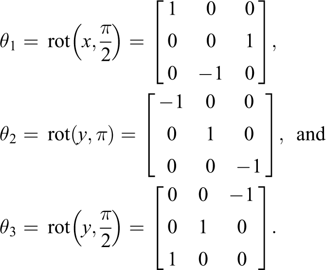
Beginning from the reference origin O and pursuing independent limbs A1A2A3A4A5A6, B1B2B3B4B5B6, C1C2C3C4C5C6, and D1D2D3D4D5D6, the following transformation matrices can be deduced
where
Starting from the initial configuration of the robot, all the instantaneous positions are completely defined by the angles of rotation and the transformation matrices . Four rotation angles of the actuators determine the input vector of the instantaneous position of the X4 robot, which is described using the output vector through the three coordinates , , and of the center G and a rotation angle ψ of the end effector around the vertical axis. The initial output of the end effector corresponds to the initial input variables . The analysis of the inverse kinematic position aims to find the mapping relations between the output vector and the input vector .
The input angles of the robot and variables , can be obtained from the following vector–chain equations
where
where represents the vector in frame {GXGYGZG}, and represents the vector in frame . Specifically, represents the vector in frame . Only one inverse geometric solution exists for the parallel robot from equation (15)
New conditions regarding the orientation of the end effector are provided by the following identities:
where is the rotation matrix of the base relative to the end effector. The resulting matrix is obtained by multiplying six basic matrices, that is, . Significant relations among the rotation angles can be obtained on the basis of the aforementioned conditions as
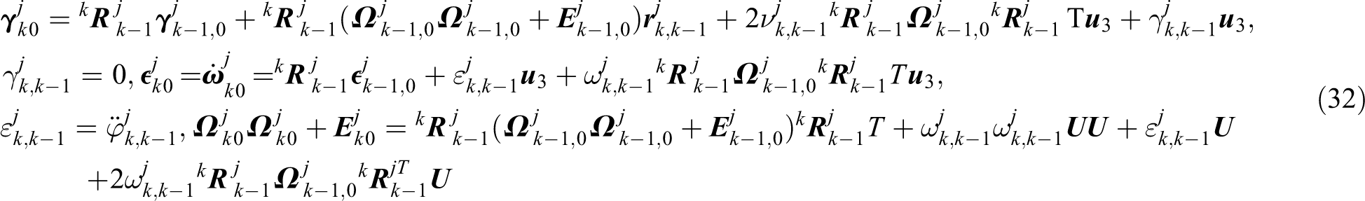
The velocities and accelerations of all moving components of the robot are deduced with the given characteristics of the translational–rotational motion of the end effector. The motions of the component elements in each limb are characterized by the following skew-symmetric matrix
which are associated with the absolute angular velocities given by the recursive relations
Following general relations provides the absolute velocities of centers of the joints as
Starting from the derivative of the geometrical constraints (15) and using the skew-symmetric matrix
associated with angular velocities of the end effector, the column matrices of relative angular velocities can be deduced as
where the 3 × 3 invertible square matrix and the column matrix are determined by the following equations
After rearrangement, the constraint in equation (17) of the X4 parallel robot can be written as
Taking the derivative of the aforementioned condition (26) with respect to time leads to the matrix equation as
As the foundation of workspace analysis and finding singular locus where the manipulator becomes uncontrollable, matrices J1 and J2 are the inverse and forward Jacobian matrices of the manipulator, respectively, and can be expressed as
where
Expressions of relative accelerations can be obtained from the following matrix equations on the basis of connectivity conditions
where the following terms determine column matrices
Starting from equations (20) to (22), the following relations provide the linear accelerations , the angular accelerations , and the significant matrices of the links from an arbitrary limb j
The matrix conditions (24) and (30) reflect the velocity and acceleration mapping from the end effector to the active joints.
Furthermore, the three kinds of singularities27 of the X4 translational–rotational parallel robot are discussed through the analysis of the Jacobian matrices J1 and J2. If matrix J1 is rank deficient, then the redundant input (RI) singularity occurs where the end effector loses a DOF because of the leg singular. When the matrix J2 is rank deficient, the redundant output (RO) singularity occurs where an uncontrollable motion of the end effector with locked actuators is observed. In addition, when matrices J1 and J2 are rank deficient, redundant passive motion (RPM) singularity appears.
Considering , matrix J1 is rank deficient, and
If , then can be obtained only when or . With limb A as an example, when , then , indicating that RI singularity occurs when all rods of limb A are located on the OX0Y0 plane. If all limbs reach this configuration simultaneously, then and J2 is rank deficient, which results in RPM singularity. The condition means that point A6 is located on axis and RI singularities occur. When , the end effector coincides with the fixed platform and the mechanism interferes. In practical applications, should be greater than zero, and the aforementioned singularities are avoided.
Otherwise, if , then equation (33) is equivalent to
When the active rod coincides with the passive parallelogram plane, the aforementioned equation holds. Therefore, RI singularities will occur if any limb reaches the collinear configuration, as shown in Figure 4.
RI singular configurations when . RI: redundant input.
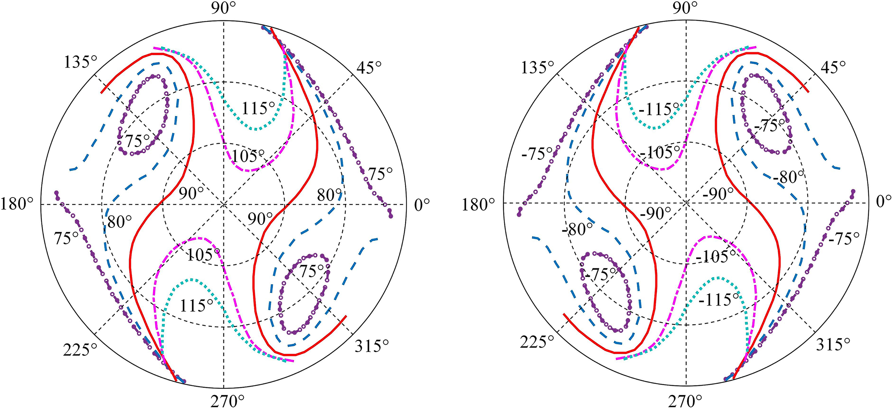
Considering the complexity of the matrix J2, obtaining the analytical solutions for J2 rank deficiency can be tedious and time-consuming. RO singularity is analyzed using the numerical method. Assuming that , the end effector moves in the horizontal plane where , and the radius of the workspace is 600 mm. The distribution of RO singularity locus that corresponds to different rotation angles of the end effector can be deduced, as shown in Figure 5.
RO singularity locus that considers end effector rotation angles when . RO: redundant output.
The singularity locus moves toward the center of the workspace and the singularity-free area decreases with the increase of the rotation angle of the end effector. However, the terminal rotation capability of 90° () is required to realize the standard SCARA motion. Figure 6 shows the singularity curves at different horizontal planes that consider the required maximum rotation angle . When the end effector moves in the range of m, the singularity-free region becomes a rectangular strip, which reveals the potential workspace of the X4 parallel robot. Figure 7 shows the configurations of the X4 robot when the end effector rotates −90°, −45°, 0°, 45°, and 90°, respectively. RO singularity is the key in the singularity analysis of the X4 parallel robot and directly determines the available workspace. In addition, the algebraic analysis of RO singularity is complex, whereas the numerical approach is convenient.
RO singularity locus in different horizontal planes with . RO: redundant output.
Configurations of the X4 robot with different rotational angles.
Simulation
A kinematic program of the X4 parallel robot is developed to implement the inverse kinematics using the software MATLAB. In the simulation, the end effector begins at rest from the initial configuration and tracks the translational–rotational trajectory. The X4 parallel manipulator with the following architectural characteristics is analyzed.
The end effector begins from the configuration , and the moving time is s. Considering the actual pick-and-place conditions, a typical trajectory is adapted to conduct the simulation. The end effector performs a 0.2 m translation along the X0 axis and rotates 30° simultaneously around the vertical axis while all the other positional parameters remain unchanged. The analytical functions of and are expressed as
Time–history graphs for the input rotation angles (Figure 8), angular velocities (Figure 9), and angular accelerations (Figure 10) are shown. Figure 8 shows that the maximum input angle of the X4 robot is only 0.526 radian (approximately 30°) during the moving process. The maximum input angular velocity is required only 1.7 rad/s (16.2 r/min) to generate the terminal velocity (the maximum translational velocity is 0.628 m/s.). Small required inputs indicate the potential of the X4 parallel robot for high-speed motion.
Input angle of rotation .
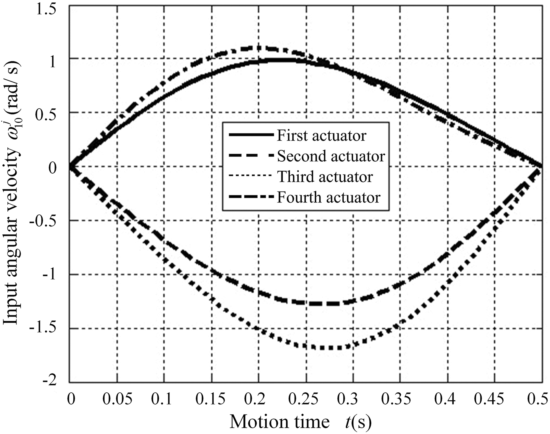
Input angular velocity .
Input angular acceleration .
In addition to input variables, the rotation angles, angular velocities, and angular accelerations of all the passive joints can be conveniently acquired through the proposed kinematics. Developments of the representative passive joint variables are derived and presented; such variables include the rotation angles and , the corresponding angular velocities and , and the corresponding angular accelerations and . Graphs for the rotation angle , angular velocity , and angular acceleration are illustrated in Figures 11, 12, and 13, respectively. Graphs for the rotation angle , angular velocity , and angular acceleration are presented in Figures 14, 15, and 16, respectively.
Angle of rotation of four legs.
Angular velocity of four legs.
Angular acceleration of four legs.
Angle of rotation of four legs.
Angular velocity of four legs.
Angular acceleration of four legs.
Conclusions
Kinematic issues of the novel X4 parallel robot are investigated in this article. The DOF number of the X4 parallel robot is verified on the basis of screw theory, which verifies that the X4 parallel robot can realize the typical SCARA motion, that is, three translations and one rotation. The inverse kinematic model is established using the recursive matrix method, and kinematic Jacobian matrices are deduced. Exact matrix relations that provide the position, velocity, and acceleration of each element of the X4 parallel robot are deduced. Singularity locus is determined by considering different singularity types, and the potential rectangle workspace is determined. RO singularity is generally the key in the singularity analysis of the X4 parallel robot, which determines the available workspace. In addition, kinematic simulations are conducted and verify the feasibility of the deduced kinematic model and reveal the potential of the X4 parallel robot for high-speed motion. The kinematic analysis presented in this study is valuable for the optimal design and development of X4 parallel robots for various applications. The method presented in this study is versatile and thus suitable not only for the X4 parallel robot but also in the forward and inverse kinematics of various types of parallel mechanisms. The kinematic analysis of the X4 parallel robot will be used in depth in a future study that establishes the inverse dynamic modeling of the manipulator on the basis of two energetic ways, namely, the principle of virtual work and Lagrange equations.
Footnotes
Declaration of conflicting interests
The author(s) declared no potential conflicts of interest with respect to the research, authorship, and/or publication of this article.
Funding
The author(s) disclosed receipt of the following financial support for the research, authorship, and/or publication of this article: This research is jointly sponsored by the National Natural Science Foundation of China (No. 51575292), and National Science and Technology Major Project of China (No. 2018ZX04020001).
ORCID iD
Zhufeng Shao
Appendix I
References
1.
ShaoZ-FTangXChenX. Research on the inertia matching of the Stewart parallel manipulator. Robot Comput Integr Manuf2012; 28(6): 649–659.
2.
ShaoZ-FTangXWangL-P. Dynamic modeling and wind vibration control of the feed support system in FAST. Nonlinear Dynamics2012; 67(2): 965–985.
3.
ClavelR. Delta: a fast robot with parallel geometry. In: Proceedings of 18th international symposium on industrial robots, Lausanne, Switzerland, 26–28 April 1988, pp. 91–100. New York: Springer-Verlag.
4.
ClavelR. Device for the movement and positioning of an element in space. Patent 4976582, USA, 1990.
5.
CompanyOMarquetFPierrotF. A new high-speed 4-DOF parallel robot synthesis and modeling issues. IEEE Trans Robot2003; 19(3): 411–420.
6.
WuX-PMeiJP. Modeling and simulation on automatic sorting equipment for large quantity and multi-typed batteries based on diamond manipulator. J Mach Design2008; 25(7): 26–27.
7.
NabatVRodriguezMCompanyO. Par4: very high speed parallel robot for pick-and-place. In: IEEE/RSJ international conference on intelligent robots and systems (IROS), Edmonton, Alberta, Canada, 2–6 August 2005, pp. 553–558. Washington, DC, USA: IEEE Computer Society.
8.
XieFLiuXJ. Design and development of a high-speed and high-rotation robot with four identical arms and a single platform. Journal of Mechanisms and Robotics-Transactions of the ASME2015; 7(4): 041015.
9.
FreudensteinFAlizadeR. On the degree-of-freedom of mechanisms with variable general constraint. In: Proceedings of 4th world congress on the theory of machines and mechanisms, 8–11 September 1975, pp. 51–65. London: Mechanical Engineering Publications Ltd.
10.
HuntKH. Kinematic geometry of mechanisms. Oxford: Oxford University Press, 1978.
11.
PhillipsJ. Freedom in machinery-introducing screw theory. Cambridge: Cambridge University Press, 1984.
12.
MarghituDBCrockerMJ. Analytical elements of mechanism. Cambridge: Cambridge University Press, 2001.
13.
HuangZKongLFFangYF. Mechanism theory of parallel robotic manipulator and control. Beijing: China Machine Press, 1997.
14.
HuangZLiuJFZengDX. A general methodology for mobility analysis of mechanisms based on constraint screw theory. Science China Technological Sciences2009; 52(5): 1337–1347.
15.
KongXGosselinCM. Mobility analysis of parallel mechanisms based on screw theory and the concept of equivalent serial kinematic chain. In: 2005 ASME design engineering technical conference and computers and information in engineering conference. Long Beach, California, USA, 24–28 September, pp. 911–920. ASME.
16.
ZhaoJSZhouKFengZJ. A theory of degrees of freedom for mechanisms. Mech Mach Theory2004; 39(6): 621–643.
17.
ZhaoJSZhouKMaoDZ. A new method to study the degree of freedom of spatial parallel mechanisms. Int J Adv Manuf Technol2004; 23(3): 288–294.
18.
HuangTLiZXLiM. Conceptual design and dimensional synthesis of a novel 2dof translational parallel robot for pick-and-place operations. J Mech Des2004; 126(3): 449–455.
19.
BriotSArakelianVGlazunovV. Design and analysis of the properties of the delta inverse robot. Geophysical J Int2008; 133(2): 459–466.
20.
ChoiH-BKonnoAUchiyamaM. Inverse dynamics analysis of a 4-DOF parallel robot H4. Adv Robot2010; 24(1-2): 159–177.
21.
ChoiH-BKonnoAUchiyamaM. Singularity analysis of a novel 4-DOFs parallel robot H4 by using screw theory. In: Proceedings of the ASME 2003 international design engineering technical conferences and computers and information in engineering conference, Chicago, Illinois, USA, 2–6 September 2003, pp. 1125–1133. ASME.
22.
Gallardo-AlvaradoJ. An application of screw theory to the kinematic analysis of a delta-type robot. J Mech Sci Technol2014; 28(9): 3785–3792.
23.
StaicuS. Recursive modelling in dynamics of Delta parallel robot. Robotica2009; 27(2): 199–207.
24.
StaicuS. Matrix modeling of inverse dynamics of spatial and planar parallel robots. Multibody Syst Dyn2012; 27(2): 239–265.
25.
StaicuSZhangD. A novel dynamic modelling approach for parallel mechanisms analysis. Robot Comput Integr Manuf2008; 24(1): 167–172.
26.
StaicuSLiuX-JLiJF. Explicit dynamics equations of the constrained robotic systems. Nonlinear Dynamics2009; 58(1-2): 217–235.
27.
BonevIZlatanovDGosselinC. Singularity analysis of 3-DOF planar parallel mechanisms via screw theory. J Mech Des2003; 125(3): 573–581.