
Abstract
Drilling robot is a piece of large rock drilling equipment that integrates mechanical, electrical, and hydraulic technique, and it is a significant device for drilling and blasting. The drilling robot arm is the core component of the robot. To get intuitive and accurate modeling method to overcome the problem of the classic Denavit–Hartenberg method, for instance, the model mismatches the entity. The coordinate system fixed on the entity of Denavit–Hartenberg notation that is named coordinate-fixed Denavit–Hartenberg is creatively presented. The coordinate-fixed Denavit–Hartenberg method not only improves the accuracy and operability of kinematic analysis but also solves the workspace of drilling robot arm effectively. The drilling robot from an intelligent technology company in China is taken as the research example in this article. The homogeneous coordinate transformation matrix of each link rod is established through reasonably simplifying drilling robot arm as a multijoint structure. The coordinate-fixed Denavit–Hartenberg method is utilized for the first time in determining and verifying the kinematics equation of drilling robot arm. The kinematics equation is employed to obtain the effective workspace of drilling robot arm. The analysis results demonstrate that the design of drilling robot arm reaches the need of workspace in the actual structure as well as meets the functional requirements of drilling robot.
Introduction
At present, the technology of drilling and blasting has occupied an important position in resources exploration, transportation, and national defense construction, and so on. 1,2 As a piece of significant engineering equipment, drilling robot is widely used in tunnel, mine, and underground engineering by drilling and blasting. 3,4 It is mainly composed of drilling arm, propeller, and chassis. Drilling robot can not only greatly reduce the intensity of manual labor and improve working conditions but also easily achieve automation and improve efficiency in the actual construction process. 5 –7
The drilling arm of robot is like the “arm” of humankind, which is the central part of drilling robot. The drilling robot arm is the positioning mechanism of drilling robot, which is adopted to ensure the rock drill to work in the correct and stable condition. 8 –10 Solving the workspace of drilling robot arm is helpful to comprehend the relationship between the position, direction, and displacement of each moving link rod. Therefore, to satisfy the actual construction requirements and improve the efficiency, stability, and safety performance of tunneling, it is imperative to solve the effective workspace of drilling robot arm. Due to the similarity between drilling robot arm and multijoint robot, drilling robot arm is simplified as a multijoint structure. 11,12 The Denavit–Hartenberg (D-H) method is commonly applied in kinematic research of multijoint structure. 13 The application conditions of coordinate fixed Denavit–Hartenberg (CFDH) method are consistent with D-H method, and the CFDH method is more accurate and rational than the D-H method. Thus, the CFDH method is adopted to solve the workspace of drilling robot arm in this article.
The structure of this article is organized as follows. The second section introduces the CFDH matrix transformation method, which includes two parts, one part is the CFDH convention and link rod parameters and the other part is to establish the coordinate system of link rod. The third section compares several methods for solving the kinematic equations of robot, and the CFDH method is applied to determine the kinematic equation of drilling robot arm and verifies its correctness. The fourth section solves the workspace of drilling robot arm and analyzes the results. The fifth section makes a brief summary of the work done.
The CFDH matrix transformation method
CFDH convention and link rod parameters
A commonly utilized convention for selecting frames of reference in robotics applications is the D-H convention which was introduced by Jacques Denavit and Richard S Hartenberg in 1955. 14,15 The classic D-H method allows the coordinate system to establish on the extension of axis, leading to the problems such as inapplicability for all the joints modeling, the model mismatching the entity, and wrong local joint position analysis. To get intuitive and accurate modeling method, the coordinate system fixed on the entity of D-H notation, that is, CFDH is creatively presented.
The CFDH convention is formulated by simplifying robot as a multijoint structure and setting up a coordinate system on each link rod entity. Multijoint robot can be described kinematically using the four parameters for each link rod: length and twist angle describe the link rod itself; axis distance and joint rotation describe the link rod’s connection to a neighboring link rod. In the usual case of a revolute joint, θi is called the joint variable and the other three parameters of link rod are fixed. For prismatic joints, di is the joint variable, and the other three parameters of link rod are fixed. The definition of mechanisms by means of these parameters is a convention usually called the CFDH method.
The structure of drilling robot arm conforms to the condition of using the CFDH method. The drilling robot arm can be regarded as a mechanical arm with multiple link rods. In CFDH method, the parameters of the link rod are specified as follows. (1) Dimension parameters of link rod
Length of link rod ai : The distance between the two axes of joints i and i − 1 along the common perpendicular.
Link rod twist angle αi
: The angle between the two axes of joints i and i − 1. (2) Relation parameters of adjacent link rod
Axis distance di : The distance between two common perpendiculars in the axis i direction.
Joint rotation θi : The angle between two common perpendiculars on the plane which are vertical to the axis of joint.
Establishing coordinate system of link rod
Owing to the drilling robot arm consisting of multiple joints, it is necessary to establish coordinate system of each link rod. The coordinate system of the link rod is shown in Figure 1 and the regulation of parameters is set as follows. Coordinate axis Xi
: Along the common perpendicular of two joint axes of rod i − 1 points to the joint i; Coordinate axis Zi
: Coincide with the axis of the joint i; Coordinate axis Yi
: Determined by the right-handed Cartesian coordinates system; Origin of coordinate Oi
: When the joint axis i − 1 intersects the joint axis i, the intersection point is taken. When the axis of the joint is i − 1 and the axis of the joint is i, the intersection of the normal axis of the two axes and the axis of the joint is i. When the joint axis i − 1 and the joint sweat axis i are parallel, Oi
is the intersection point taken by the axis i and the public vertical line of the axis i + 1 and the joint axis i.
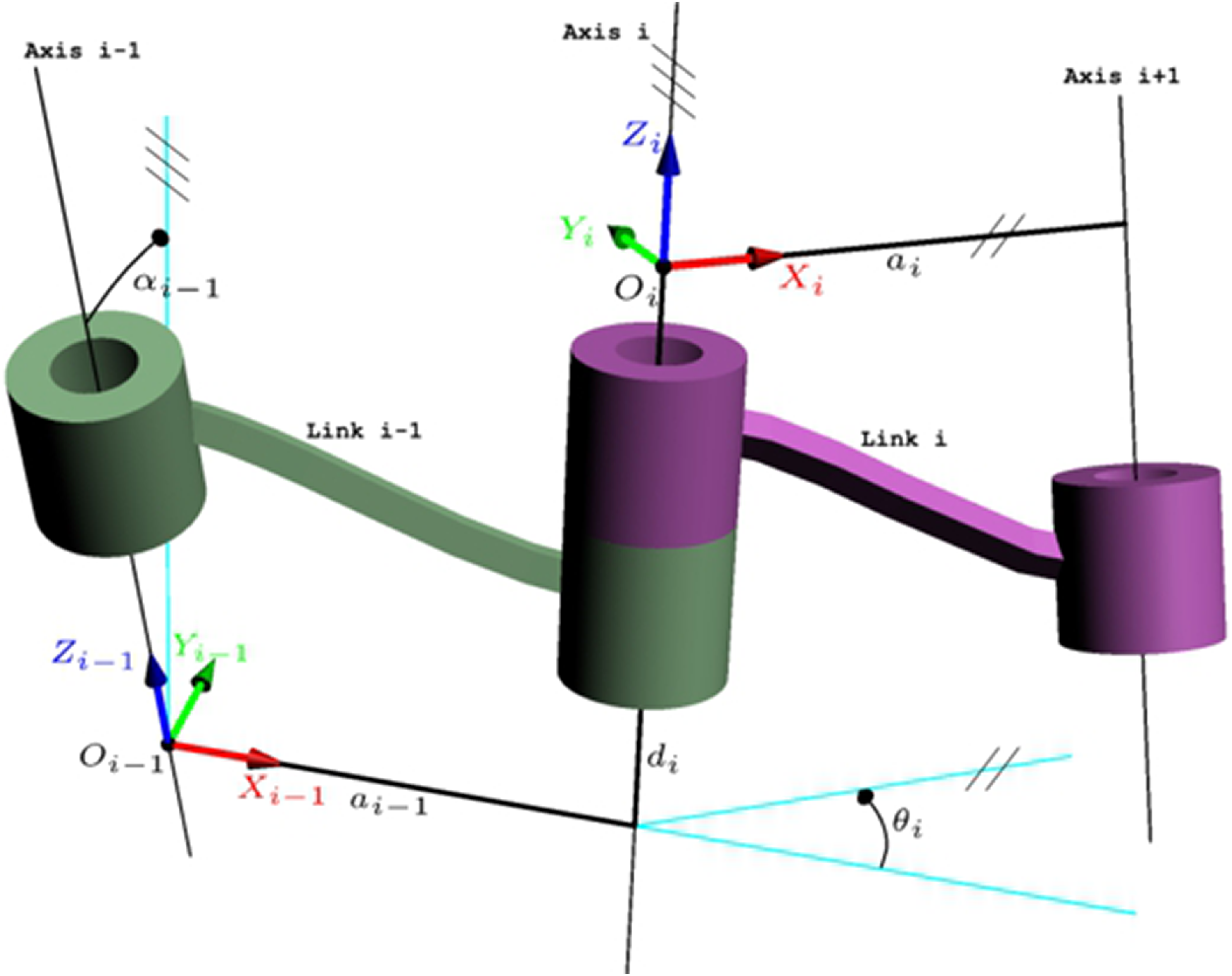
Coordinate system of link rod.
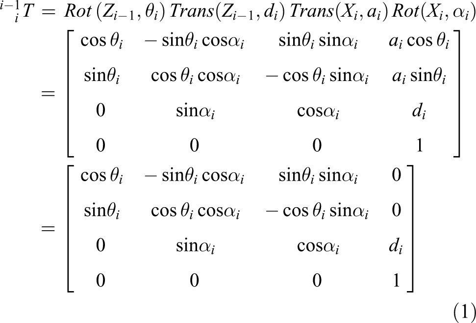
The coordinate system is established according to the CFDH method, and the transformation matrix between the two adjacent parts is converted from coordinate system {i − 1} to coordinate system {i}, which can be obtained by four transformations. Rotating θi
around Zi
− 1 axis: Translocating di
along Zi
− 1 axis: Translocating ai
along Xi
axis: Rotating αi
around Xi
axis:
The CFDH parameters of the rotating link rod are ai
, αi
, di
, θi
. The joint angle θi
is the joint variable; length of link ai
, link twist angle αi
, and link distance di
are fixed. These four parameters determine the position of the link rod {i} relative to the link rod {i − 1}. The coordinate transformation matrix is
Determination and verification of kinematic equation
Owing to the variety of robots, the methods applied in determining the kinematic equations of robot are different on the basis of different structures; in addition to the D-H method, Lie Group and Moving Frame methods are also commonly used. In the determination of the kinematic equation by applying the Lie Group method, there is no need to establish the corresponding coordinate system on each link rod, and the rotation theory can be used to calculate directly. However, as a result of its lack of intuition, the Lie Group method is difficult to obtain a precise and complete motion model of the robot. Thus, this method is more used in the study of planar robots. In the application of Moving Frame method to determine the kinematics equation of the robot, in the first place, the recursive formula of the moving frame should be gained according to the Bouquet formula of differential geometry. Then, the relative component of the moving frame set up by each link rod is calculated. Finally, the position and posture of the moving frame on the end link rod of the robot is calculated on the basis of each relative component. Although this representation method is meaningful to the trajectory planning of robot, it is more cumbersome to use and the amount of calculation is too much for a multijoint robot.
In summary, the Lie Group and Moving Frame methods have their own advantages in determining the kinematic equations of the robot. However, due to the limitations of their characteristics and the scope of application, they are not suitable for the drilling robot arm structure in this article. The CFDH method inherited the advantages of the classic D-H method and improved it. It has solved the existing technical defects of D-H method, reduced the error, improved the precision, and made it more suitable for the multijoint structure. Therefore, the CFDH method is applied to determine the kinematic equation of drilling robot arm.
Figure 2 shows the three-dimensional model of drilling robot arm. It can be seen that the drilling robot arm has a lot of joints, thus applying CFDH method is more accurate to determine its kinematic equation than other methods.
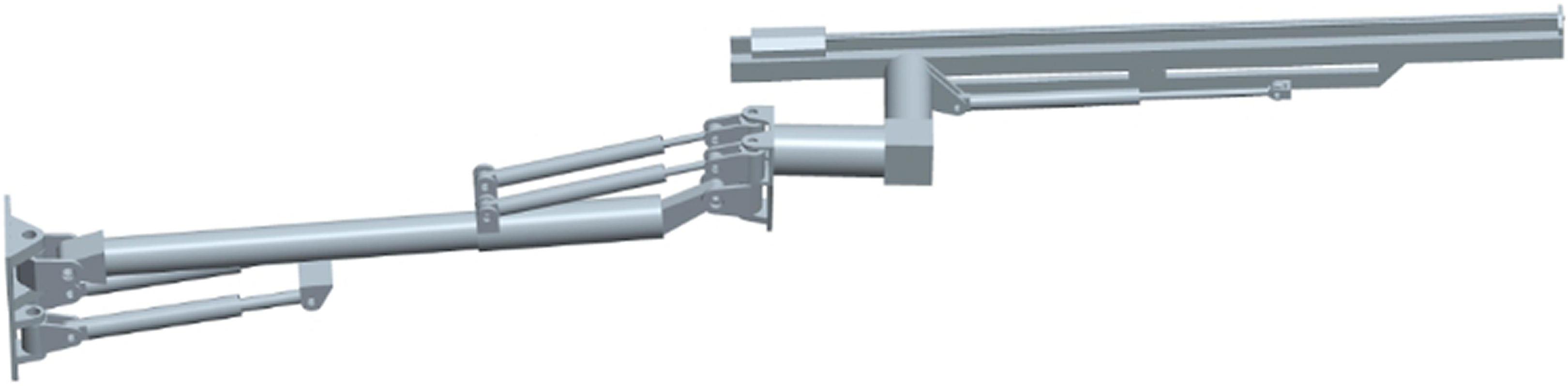
The three-dimensional model of drilling robot arm.
Because the essence of motion is the relative variation between positions of each coordinate system, the position and posture of each link rod can be expressed by the transformation matrix between the end coordinate system and the base coordinate system. To determine the kinematic equation of drilling robot arm, it is necessary to establish the coordinate system of drilling robot arm. According to the rules of CFDH method, the end coordinate system is built on the link rod which is to be described, and the base coordinate system is set on the base of mechanism. Thus, in the coordinate system of drilling robot arm, the base coordinate system {0} is arranged at the base plate of drilling robot, and the end coordinate system {7} is arranged at the top of drilling rod. The drilling robot arm is simplified as a multijoint structure and its coordinate system is established as Figure 3.

Coordinate system of drilling robot arm.
On the basis of the designing value which is provided by the intelligent technology company, the relevant data of drilling robot arm is determined as follows.

According to Formula (1) and using parameters from Table 1, the transformation matrix reflecting the link rods of drilling robot arm can be obtained as follows.


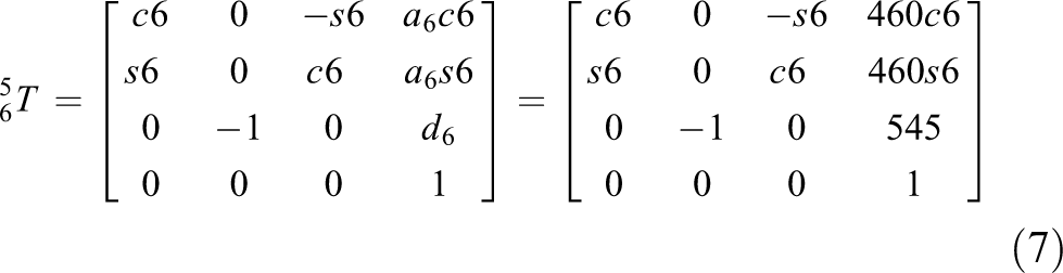

where si = sin θi , ci = cos θi (i = 1, 2, 3, 4, 5, 6)
Parameters of drilling robot arm parts.

The matrices (2), (3), (4), (5), (6), (7), and (8) are multiplied by turns. The relation matrix of the end of drilling robot arm and the base is obtained as formula (9), which is the kinematic equation of drilling robot arm.
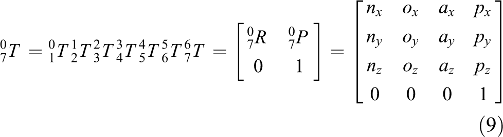
To specify the relation of one coordinate system to the other coordinate system, the origin position of coordinate system and the direction of its coordinate axis must be determined. In the Formula (9), p is the position of drilling robot arm end; n means the principal vector direction cosine of the X axis; o represents the major vector direction cosine of the Y axis; a is the main vector direction cosine of the Z axis.
According to the contents of the CFDH method, nx , ny , nz , ox , oy , oz , ax , ay , az represent the posture of the actuator at the end of drilling robot arm; px , py , pz represent the position of the actuator at the end of drilling robot arm.

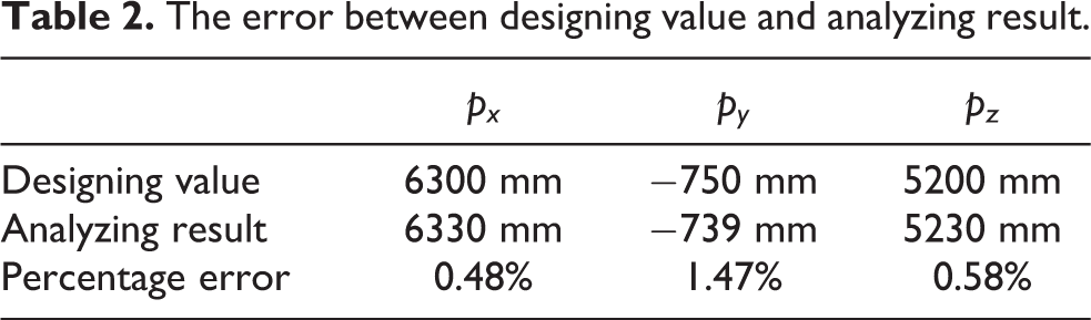
According to the designing value which is provided by the intelligent technology company, the initial state of the drilling robot arm is determined as px =6300 mm, py = −750 mm, pz = 5200 mm.
The correctness of the kinematics equation can be verified by substituting the numerical value into formula (10). Taking numerical values from joint variable θ 0 = θ 1 = θ 2 = θ 5 = θ 6 = 0°; θ 3 = θ 4 = 90°; d 7 = 3000 mm; l 1 = 0 mm, the analyzing result through the kinematic equation is that px′ = 6330 mm, py′ = −739 mm, pz′ = 5230 mm.
In the light of the regulation, the error range between designing value and analyzing result is within 5% and indicates that the kinematic equation is correct. As shown from Table 2, the errors are far less than the specified error range, thus it can be seen that the kinematics equation of drilling robot arm determined by the CFDH method is correct.
The error between designing value and analyzing result.
Solving the workspace of the drilling robot arm
Based on the analysis of the drilling robot arm structure and kinematics, another important work is to solve the workspace of drilling robot arm. The determination of the kinematic equation through CFDH method facilitates the solution of the workspace. The workspace of drilling robot arm is a vital index to judge the working ability of drilling robot.
There are many methods to solve workspace of drilling robot arm, and each has its own characteristics. Using the envelope boundary constraint conditions, this method is very complicated and the intuitive nature is not strong. 16 The graphic method is simple but not very accurate. Above two methods are only applicable to the case of low degrees of freedom. In the numerical method, a value is directly substituted into the formula to determine whether the equation or unequation is founded. If not, the numerical value needs to be adjusted. This article adopts a similar method in the numerical method. It can not only omit the kinematics calculation but also improve the operation speed, and the results of intuitive nature are strong. 17
Programming in the MATLAB software, each joint numerical value is selected randomly within the range of numerical value (the numerical value is shown in Table 1). Bringing the numerical value into kinematics equation, the three-dimensional coordinate value of the end point of drilling robot arm is achieved. The three-dimensional coordinate points output to the graph device by using “plot” function, and the workspace of the drilling robot arm is obtained. By using the “for” cycle to select 15,000 points randomly, the workspace diagram of drilling robot arm can be formed. The graphs of workspace are shown in Figures 4 and 5.

The three-dimensional graph of workspace.

The graph of workspace on the XOY surface.
Random joint variables are calculated as shown in the formula (11).

In the formula (11), θi min is the minimum numerical value of rotation range of the joint i, θi max is the maximum numerical value of rotation range of the joint i, rand (1) refers to the number of randomly selected 0∼1.
The drilling rod end position is the workspace of drilling robot arm, as shown in the Figure 4. It can be seen that the workspace of drilling robot arm is similar to a half hollow ellipsoid. The three-dimensional graph of workspace is basis of the graph on the XOY, XOZ, and YOZ surfaces. Therefore, if we intend to gain the workspace on the rock face, the three-dimensional graph of workspace must be obtained.
The drilling robot arm is mainly working on the tunnel face. Thus, in the actual construction, the XOY surface of workspace is the most significant and the best reflect of its kinematic performance. In combination with the Figure 5, it can be seen that the projected points on the XOY surface are distributed in a sector. The data analysis shows that the fan radius is 8000 mm. According to the design index, the XOY surface of workspace is centered on the sector with a radius of 6000 mm. Therefore, the drilling robot arm satisfies the workplace requirement of drilling robot on the tunnel face.
The XOZ and YOZ surfaces of workspace mainly describe the drilling area that the drilling robot arm can reach on the side, top, and bottom of the tunnel. As shown in Figures 6 and 7, the projected points of workspace on the XOZ and YOZ surfaces are similar to rectangles. The data analysis shows that the drilling areas are 14,000 × 9000 mm2 and 16,000 × 9000 mm2. On the basis of the design index, the drilling areas of XOZ and YOZ surfaces are the focus on 12,000 × 8000 mm2. Thus, the drilling robot arm satisfies the workplace requirement of the drilling robot.
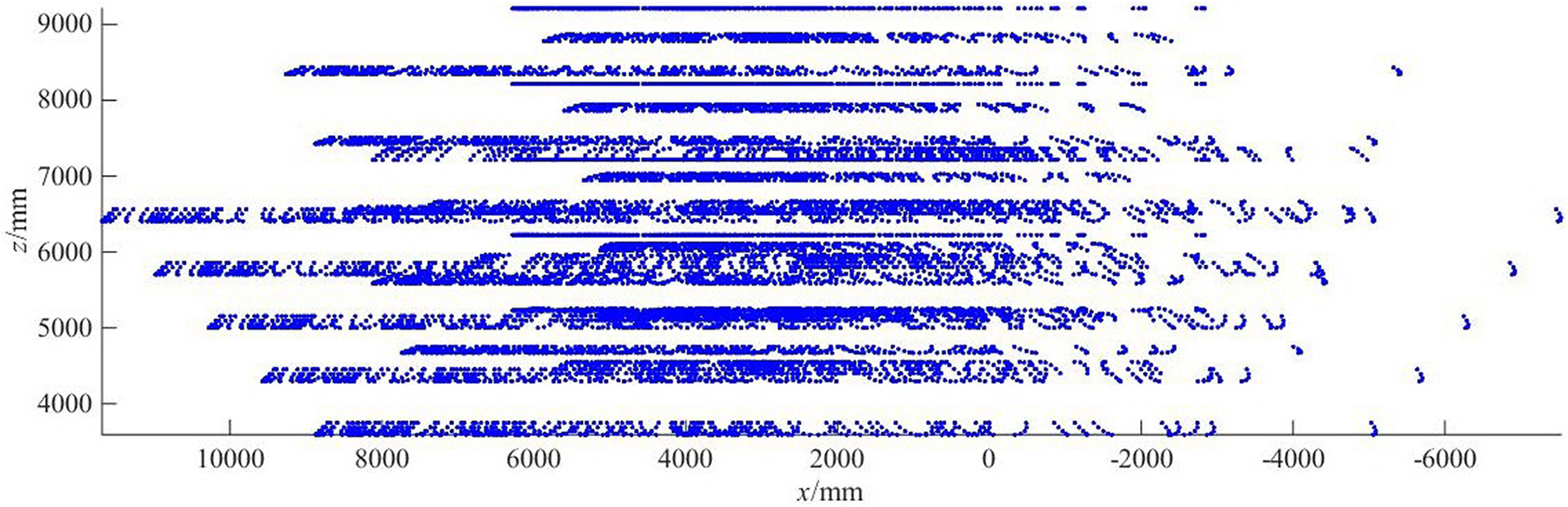
The graph of workspace on the XOZ surface.

The graph of workspace on the YOZ surface.
In summary, through the solution and analysis of workspace, it can be proved that the drilling robot arm studied in this article meets the construction requirements of drilling robot.
Conclusion
In this article, an improved method of solving workspace is developed to ameliorate drawbacks of the conventional method, while this method is still easy to operate and generalize. The coordinate system of CFDH method is fixed on the entity and therefore, the accuracy of workspace can be improved. The drilling robot arm is simplified into a multijoint structure and its coordinate system is established. The transformation matrix between components is obtained using the CFDH method, and the kinematic equation of drilling robot arm is successfully determined and effectively verified. Consequently, the end position of the drilling rod and the workspace of drilling robot arm are gained, and it is proved that the drilling robot arm satisfies the construction requirements of drilling robot. The effective workspace of drilling robot arm is helpful to comprehend the relationship between the position, direction, and the displacement of each moving rod. Meanwhile, it is the foundation of establishing the dynamic equation of the drilling robot arm.
Footnotes
Declaration of conflicting interests
The authors declared no potential conflicts of interest with respect to research, authorship, and/or publication of this article.
Funding
The authors disclosed receipt of following financial support for the research, authorship, and/or publication of this article: This research is financially supported by the National Science Foundation of China (grant no. 51275374).