
Abstract
Unmanned air systems are becoming ever more important in modern societies but raise a number of unresolved problems. There are legal issues with the operation of these vehicles in nonsegregated airspace, and a pressing requirement to solve these issues is the development and testing of reliable and safe mechanisms to avoid collision in flight. In this article, we describe a sense and avoid subsystem developed for a maritime patrol unmanned air system. The article starts with a description of the unmanned air system, that was developed specifically for maritime patrol operations, and proceeds with a discussion of possible ways to guarantee that the unmanned air system does not collide with other flying objects. In the system developed, the position of the unmanned air system is obtained by the global positioning system and that of other flying objects is reported via a data link with a ground control station. This assumes that the detection of those flying objects is done by a radar in the ground or by self-reporting via a traffic monitoring system (such as automatic identification system). The algorithm developed is based on game theory. The approach is to handle both the procedures, threat detection phase and collision avoidance maneuver, in a unified fashion, where the optimal command for each possible relative attitude of the obstacle is computed off-line, therefore requiring low processing power for real-time operation. This work was done under the research project named SEAGULL that aims to improve maritime situational awareness using fleets of unmanned air system, where collision avoidance becomes a major concern.
Keywords
Introduction and motivation
Most coastal states have a problem with monitoring maritime activities in their waters, since it is necessary to patrol vast areas and resources are always scarce. This monitoring is commonly known as maritime situational awareness 1 and was traditionally achieved with coastal radars, manned patrol boats, maritime patrol aircraft (MPA), and self-reporting systems such as automatic identification system (AIS). These systems tend, however, to be quite expensive to maintain, especially since there is usually a need to keep manned systems (patrol boats or MPAs) available to check the situation in loco. In recent years, unmanned air systems (UASs) have become a very attractive alternative to manned systems, since they are usually much cheaper to operate and are becoming more and more capable.
However, the use of UAS in nonsegregated airspace raises many legal and safety problems due to the risk of collision between vehicles. Hence, it is important to develop and test reliable and safe methods to avoid collision, and a lot of work has been done in this area. 2 For maritime patrol, and in the SEAGULL project in particular, the main risk of collision is between different UASs, 3 since a fleet of vehicles will be used. This problem is easier to tackle since all vehicles will be using the same collision avoidance methods, and in some cases the vehicles will be flying in formations, where this problem has also been studied. 4 According to Schaeffer, 5 in the United States, there are approximately 0.5 midair collisions per 1 million flight hours. Most of these collisions happen in uncontrolled airspace where there is no coordinating entity, and thus a decentralized approach, where each vehicle must act independently, is essential. 6
There is a vast body of literature concerning the topic of sense and avoid systems. Existing approaches include rule-based, artificial potential fields, probabilistic, evolutionary, and dynamic optimization. A comprehensive review of those approaches is out of scope of this article. Instead, we refer the reader to the work of Yu and Zhang, 7 where more than 100 publications are categorized according to the techniques employed for obstacle (also denominated intruder) detection and path replanning. A complementary and slightly more recent survey can be found in the study by Sahawneh. 8
One key aspect that seems to be transversal to most approaches is the distinction between the threat detection phase and the collision avoidance maneuver. The approach proposed in this article handles both procedures in a unified fashion. In particular, the proposed algorithm precomputes the set of positions of the obstacle corresponding to safety threats and also the control (or controls) providing the corresponding optimal evasive action.
The proposed sense and avoid system is based on a dynamic programming technique, more specifically on deterministic differential zero-sum games with two players. 9,10 This theoretical framework was previously applied to collision avoidance systems in an earlier study. 11 One of the advantages of this framework, when compared, for instance, with pure geometrical approaches (see, e.g. Fasano et al. 12 ), resides in the fact that it provides a systematic way of identifying the threat zones for any shape of the aircraft exclusion zone. This may contribute to decrease the number of deviations from the desired path when the exclusion zone is not defined as a simple circle (or cylinder, in the three-dimensional (3-D) case). Other key advantage of this approach is the low processing requirements for real-time operation, since the optimal controls for each possible relative attitude of the obstacle are computed off-line.
As opposed to the approach described in the work of Mitchell et al., 11 which only provides approximations of the threat zones, the numerical methods employed in this work ensure that the resulting controller provides collision avoidance for the considered discretization of the state space and controller sampling rate. This is done by computing over-approximations of those zones. Moreover, the proposed controller was already integrated and tested in the computational system described in this work, thus showing the feasibility of the approach.
This article is an extended version of the work by Marques et al., 13 and besides a short description of the UAS developed for the SEAGULL project, mainly to provide context, it focuses essentially on the sense and avoid algorithms for collision avoidance. Software-in-the-loop simulations of the implemented real-time sense and avoid system illustrate the effectiveness of the proposed controller. At the end of the article, we present a discussion of the results obtained with this project.
System overview
System architecture
The SEAGULL system architecture is based on open architectures, maximizing the use of standard components, protocols, and interfaces (both hardware and software). This not only reduces development and construction times and costs but also maximizes interoperability, flexibility, and durability of the systems. The general architecture of the UAS is presented in Figure 1. The main blocks are the platform command and control functionalities (SEC2, from the Portuguese initials of the name) and payload sensors and systems, which are used to detect objects (SEP, from the Portuguese initials of the name).

General overview of the SEAGULL system.
The system architecture is presented here from two distinct perspectives: the computational components that compose the system, responsible for performing the navigation control and the mission payload software; the hardware and flight-related components that compose the platform (the unmanned aerial vehicle (UAV) itself), responsible for the UAV’s capabilities that guarantee its physical operation, from launch to flight and landing.
Computational system
The platform command and control system is based on a Piccolo autopilot, 14 which is a commercial off-the-shelf device widely used in UAVs. Basically, it uses a differential global positioning system (DGPS), inertial and air data sensors and controls the motor and control surfaces of the UAV. Aboard the vehicle, the autopilot communicates, via a serial link, with the platform’s embedded command and control computer (SEC2), which in turn communicates via an Ethernet network with the payload subsystems (SEP). The autopilot also has a radio link that connects it to a ground control station (ETC2), which in turn passes relevant payload information to the payload ground station (ETP), that may or may not be linked to the maritime operations support and information system (SISOM).
The computers that were used to perform the computational processing onboard are based on the PC104 architecture (Figure 2). The PC104 form factor was a good match for usage in the UAV domain due to the reduced size of the rugged computers, which albeit small have high processing power and a modular design that allows additional boards to be stacked to the main processor board.

Computational platform (PC104 onboard computers).
The SEC2 computer was comprised of the main and power boards, while the SEP computer was stacked with two extension boards, one to provide additional Ethernet ports (required for sensors’ connection) and another one with frame grabber capabilities, required to operate one of the cameras used on the UAV. Each computer had a solid-state drive hard disk connected to it, to store the images and data from the onboard sensors, autopilot telemetry and detailed system logs for off-line analysis (to support off-line analysis, debug, and features validation).
As a maritime patrol asset, the UAV is equipped with an AIS that receives self-reported information from ships, such as maritime mobile service identity, flag, and GPS location. It also has a computer vision system with three cameras operating at different spectra: thermal, near infrared, and visible. Once a target has been detected, its location is passed to the SEC2 onboard computer, which runs the target-tracking controller and ensures that the target of interest remains in the center of the image frame. 15
Regarding the ground stations, the computers were rugged laptops. These laptops are common among the military, since they are designed for usage in harsh environmental conditions, namely outdoor missions, providing high resistance to water spills and general wet conditions, falls and vibrations, with displays capable of operating under direct sunlight.
The SEAGULL system uses the robot operating system (ROS) middleware, 16 which has become one of the most popular and widespread frameworks for mobile robotics. ROS is particularly useful during the development phase thanks to its ability to record data through ROS’s rosbag package, which greatly facilitates debugging. It also has a very comprehensive library of functions to interact with different sensors, actuators, and payload.
During validation and operational missions’ execution phases, several flights were performed. The climate conditions during these flights varied considerably with temperatures between 28°C and 34°C (with the UAV under direct sunlight for several hours), wind speed from 10 to 15 knots, with maximum crosswinds of 6 knots, and throughout the tests we had a wet environment since we were operating at sea.
These conditions did not present any particular difficulties to the components used in the system—the ground stations were able to operate well, both indoors and outdoors, and the onboard computers worked continuously, without any downtimes or crashes occurring. Apart from refuel and navigation checklist processes, the UAV was ready to take off for a new mission, almost immediately after landing (Figure 3).

SEAGULL UAV between operational mission flights. UAV: unmanned aerial vehicle.
It is reasonable to state that the platform design choices resulted in a solid and stable UAV, oriented and well suited to achieve its specific goal—the usage of UAVs to perform maritime missions and increase situational awareness of the patrolled areas.
UAV platform components
As shown in Figure 4, SEAGULL is a system comprised of four main components: the UAV, the ground control station (GCS) that comprises the command and control ground station (ETC2), the payload station (ETP), and the external SISOM station.

SEAGULL system.
It should be stressed that the communication between the UAV and the ground segment is established over a communication line of sight link (ultrahigh frequency (UHF) band) and/or via satellite communications (SATCOM). ETC2 is the GCS responsible for controlling and monitoring the UAV subsystems. On the other hand, the ETP station is responsible for monitoring data relating to the mission to be performed by the UAV or the payload.
The key physical components, or subsystems, that define the UAV platform are the structural subsystem, the propulsion subsystem, the communications subsystem, the secondary flight subsystem, the power subsystem, the payload subsystem, and the primary flight subsystem.
The structural subsystem, the UAV itself, was the Alfa Extended, which is one of the platforms built from scratch at the Portuguese Air Force Academy Research Center. The general characteristics are length 1.9 m, wingspan 3.5 m, maximum take-off weight 25 kg, engines 3 W 28i (28 cc; 1500–8500 r/min), payload 8 kg, maximum speed 144 km/h, cruise speed 90 km/h, autonomy (endurance) 4 h, autonomy (range) 90 km, and altitude 2000 m.
The structural subsystem consists of the following five components: the fuselage, the wing, stabilizers, flight control surfaces, and landing gear. The UAV engine, together with associated fuel subsystem and related hardware for its monitoring, is referred to as propulsion subsystem. The purpose of the propulsion subsystem is to generate a thrust force that propels the UAV in flight. The communications subsystem allows all UAV communications (ETC2–autopilot) and additionally allows communication between the embedded sensors onboard the UAV and the GCS. To achieve that, this subsystem comprises three main components: the UHF communications component, the SATCOM component, and the payload communications component. The secondary flight subsystem, commonly referred to as the UAV avionics, is the subsystem that comprises all the components that do not directly influence the UAV flight performance. Nevertheless, those components are important for measuring flight properties and flight performance. As a matter of fact, they provide very useful measurements that enable the operator to effectively fly the UAV. The avionics components in the SEAGULL UAV are the transponder, the DGPS (necessary for precision autonomous landing), and the laser altimeter (that indicates flight altitude above sea level). The power supply system is comprised of a generator connected to the main engine, backup batteries, and a power management board. The payload subsystem must comprise all necessary sensors for mission accomplishment. Finally, the primary flight subsystem is composed of the autopilot, the Pitot tube, and mechanical actuators. This subsystem is responsible for performing basic navigation, flight planning, trajectory forecast, performance and guidance data calculation, as well as providing an interface to other onboard components.
Sense and avoid
This section describes the development and implementation of a control strategy for preventing collisions between the controlled UAV and other objects flying at the same altitude, allowing the UAV to operate in shared mixed-initiative areas. 17,18
One important requisite is that the UAV should be operated at a constant altitude. Therefore, the sense and avoid system should work with the challenging restriction of only being able to change the aircraft orientation in order to avoid possible obstacles. To this end, we propose a control strategy using the theory of deterministic differential two-person zero-sum games, 9,10 where the objective of the controlled aircraft (evader) is to avoid reaching a given exclusion zone. The exclusion zone is the set of states that, a priori, are known to imply imminent collision. This set will depend on the model used to describe the motion of the aircraft and obstacles. In this article, the approach of Nimmich and Goward 1 is extended and improved by considering two classes of obstacles: obstacles possessing the ability of changing their velocity vector (magnitude and direction) instantaneously and obstacles constrained to motion with bounded curvature. The implementation of the proposed controller for a computer-based platform is also discussed.
System model
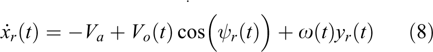
The aircraft motion dynamics in cruise mode are approximated by


where Va is the aircraft linear speed; the pair (n(t), e(t)) defines the aircraft position in the North-East reference frame; ψ(t) is the aircraft orientation; (cn (t, n, e), ce (t, n, e)) denotes the spatiotemporal varying wind speed vector; and ω(t) ∈ [ω max , ω max] is the angular velocity command. This is the abstract model of the aircraft curving procedure, which is usually done by varying the bank angle. The bounds for the angular velocity command are based on the aircraft specifications.
The first class of considered obstacles can change their speed Vo (t) ∈ [V min, V max] and heading ψo (t) instantaneously. In this case, the motion of the obstacle satisfies


where (no, eo ) is the obstacle position in the local earth-fixed frame. The obstacle speed is assumed to be not greater than the controlled aircraft cruise speed. In the case of multivehicle operation, if all aircrafts are equipped with the sense–avoid controller, then collision-free operation between any pair of vehicles is ensured, since the controller ensures that the fastest aircraft is able to avoid the slowest (actually, it is sufficient that the n − 1 fastest aircrafts are equipped with the sense–avoid controller). In that case, the controller must be synthetized for each type of aircraft, taking its maximum operational speed and minimum curvature radius into consideration. Otherwise, it is well known that any controllable object moving in free two-dimensional space will eventually be able to reach a neighborhood, function of speed and minimum curvature radius differentials, of any other object traveling at a smaller speed. Safety with relationship to faster objects can only be ensured under some assumptions regarding their trajectory, as hinted in our analysis with respect to obstacles moving with constant bearing. However, we leave an in-depth analysis of these scenarios as future work.
Note that this model will lead to very conservative designs, since the controller must be able to cope with obstacles with very flexible dynamics. Since, in most scenarios, the expected obstacles will consist of other planes traveling along straight line paths or performing smooth curves, we consider a second class of obstacles, for which the heading of the obstacle is defined as a state with dynamics given by

where ωo (t) ∈ [ωo ,max , ωo ,max] and Vo (t) ∈ [V min, V max] are the exogenous inputs.
The objective of the controller is to change the aircraft orientation in order to avoid the obstacles reaching a certain specified neighborhood of the position of the aircraft. To achieve this objective, it is convenient to model the motion of the obstacle relatively to the position of the aircraft. Consider the coordinate transformation

where (xr, yr ) defines the position of the obstacle with respect to the aircraft longitudinal and transversal axes, respectively. Moreover, assuming that for the intended range of obstacle detection, both the controlled aircraft and obstacles are subject to similar wind conditions, it follows that the terms (cn (t, n, e), ce (t, n, e)) are cancelled when considering the relative motion in the body-fixed frame. Thus, the motion of the obstacle in the aircraft’s body-fixed frame is described as follows

where ψr (t) = ψo (t)·ψ(t) is the relative heading. Note that for the first class of obstacles, for which ψo (t) may change instantaneously, the actual orientation of the controlled aircraft is irrelevant in the context of the optimization process. This is due to the fact that, at any given time and for any aircraft heading, the obstacle may choose a heading ψo (t) such that ψr (t) corresponds to the worst-case scenario. For the second class of obstacles, the evolution of the heading of the obstacle in the aircraft’s body-fixed frame satisfies

Controller design
For notational compactness, consider a system of the form

where x(t) in ℝ3 is the obstacle posture relatively to the controlled aircraft (2 Cartesian coordinates plus the direction angle), u(t) ∈ U is the aircraft control input, and v(t) ∈ V is the exogenous input driving the obstacle. Note that for the first class of obstacles, since the direction can change instantaneously, we have just two dimensions with x(t) = (xr (t), yr (t)), and v(t) = (Vo (t), ψr (t)). For the second class of obstacles, x(t) = (xr (t), yr (t), ψr (t)) and b(t) = (Vo (t), ωo (t)). In both cases, the control input vector u(t) is defined by ω(t).
Let tf be the time to collision that depends on the initial poses of the vehicle and obstacle and on their future trajectories, which are consequently related to the input signals of the aircraft and the object. The rationale of the controller is to select the input signal u(t) that maximizes tf , given the worst-case scenario of the movement of the object. More precisely, the controller is based on the solution of the following deterministic differential game

where fu
defines the evader’s strategy,
From the above, consider now the set-valued function of the safest controls defined as
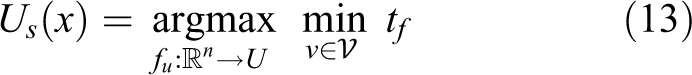
subject to the same constraints of the earlier study. 14 This set will be computed off-line as will be described in the next subsection.
The collision avoidance module will act as a filter for the higher level autopilot reference. Assuming that the autopilot reference is uc , the collision avoidance control law is finally given by

For implementation purposes and even for high-level monitoring, it is convenient to classify the state space in accordance with the hazard level. Therefore, the space state is classified accordingly into the following categories: exclusion (A), danger (B), alert (C), and safe (D), as illustrated in Figure 5.

Sense and avoid control algorithm assuming obstacles with no curvature constraints. From the inner (circle) to the outer set: exclusion (A), danger (B), alert (C), and safe (D) zones.
The exclusion zone, corresponding to an actual collision, is defined as

The danger zone, defined as

is the set of states for which an obstacle that pursues the aircraft following an optimal strategy would always be able to reach the exclusion zone. Should any obstacle unexpectedly reach this area, the controller will only allow controls corresponding to the maximization of the time to collision. In this scenario, the vehicle may engage other emergency measures (e.g. opt to change altitude), thus the usefulness of this categorization. The alert zone, defined as

is the set of states for which there is no danger of collision, provided that the aircraft employs the action indicated by the controller. Finally, the safe zone is the set of states for which the aircraft may safely follow any desired direction. The safe zone is the complement of A ∪ B ∪ C.
Implementation details
The main problem in this approach consists of the off-line computation of T(x). To this end, we used a dynamic programming framework, using numerical methods. However, in general, when numerical methods are used, the exact solution of the problem is not achievable. Even a closed-form description of the approximation of T(x) may be hard to achieve, depending on the desired level of accuracy.
In order to make the problem more tractable, a set of approximations are considered. First, the value function is defined only for a finite subset D of the state space. This set must contain A ∪ B ∪ C. Moreover, the set D is partitioned into a regular grid, which implies that all the sets are described as a set of small cells. Second, a discrete-time system model is considered following the principles of viability theory. 19
Further, in order to ensure that the controller will not allow obstacles to reach the exclusion zone between sampling instants, the evaluation of the simulated trajectories was done in smaller steps, to ensure that the evolution of the system trajectory between time steps is limited to adjacent cells and, therefore, the passage through each cell is detected. We remark that this procedure is required only at the design stage, during off-line computation of the optimal=controls and different hazard zones. The deployed system will simply use the optimal control precomputed for each region of the state space, according to the chosen state-space discretization, as described in section “Implementation details.” The final control system still uses Δ as the interval between sampling instants (and respective control actions), as stated initially.
Finally, the computation of V(x) is performed using a value iteration algorithm (e.g. Bertsekas 20 )).
In order to deploy the collision avoidance controller in the computer-based control system, Us (x) is stored as a set-valued lookup table, explicitly defined only for x ∈ D. During real-time operation, at each control cycle, the controller identifies the cell containing the current state and maps that state to the grid node associated with the cell. Whenever the obstacle is in a safe cell, the controller does not affect the command issued by the autopilot. The same applies whenever the obstacle is outside D or there is no detected obstacle.
It is important to stress that the proposed collision avoidance control strategy satisfies the following desired aspects: The controller has low real-time processing requirements. There is no need to evaluate multiple candidate trajectories during real-time operation. The storage requirements can also be easily met by common computational systems, given the low dimensionality of the considered system models. The controller can handle static and moving obstacles. The controller has a deterministic behavior, with obstacle avoidance formally ensured as long as the design stage assumptions are met, namely the bounds on system inputs. Given that, in this kind of application, a collision entails considerable economic and security consequences, we consider that the extra conservativeness obtained by the deterministic approach, as opposed, for instance, to a stochastic approach, is acceptable. The control synthesis can be fully automated, with no dependence on any kind of human-dependent geometrical or analytical procedure.
Simulation scenario 1: Bounded speed obstacles with unconstrained motion
The controller was implemented using the C++ programming language and was integrated in the final SEAGULL system. In this subsection, we describe the simulation results obtained from software-in-loop testing. The exact same code from the target system is used except for the sensor and actuator modules, which are replaced by virtual devices connected to a simulation engine.
The following model parameters, corresponding to the aircraft operating specifications, were considered: V = 25 m/s, ω max = 0.18 rad/s, V min = V max = 25 m/s, and Δ = 1 s.
The exclusion zone was specified as a 20 m radius circle centered at the origin of the aircraft’s body-fixed frame.
The computation of the value function was performed using a 301 × 201 node regular grid, with a spatial resolution of 2 m. The set of controls for the obstacle were discretized as a single value for input Vo (t) and 121 equally spaced values for input ψr (t). Figure 5 shows the resulting classification of each region of the state space, accordingly to the hazard level.
In what follows, it is assumed that the aircraft is requested to travel to a given waypoint, specified by its coordinates (nd , ed ) in the earth-fixed frame, using the “line-of-sight” (LOS) guidance law:


where sat(x, x min, x max) = min(max(x min, x), x max).
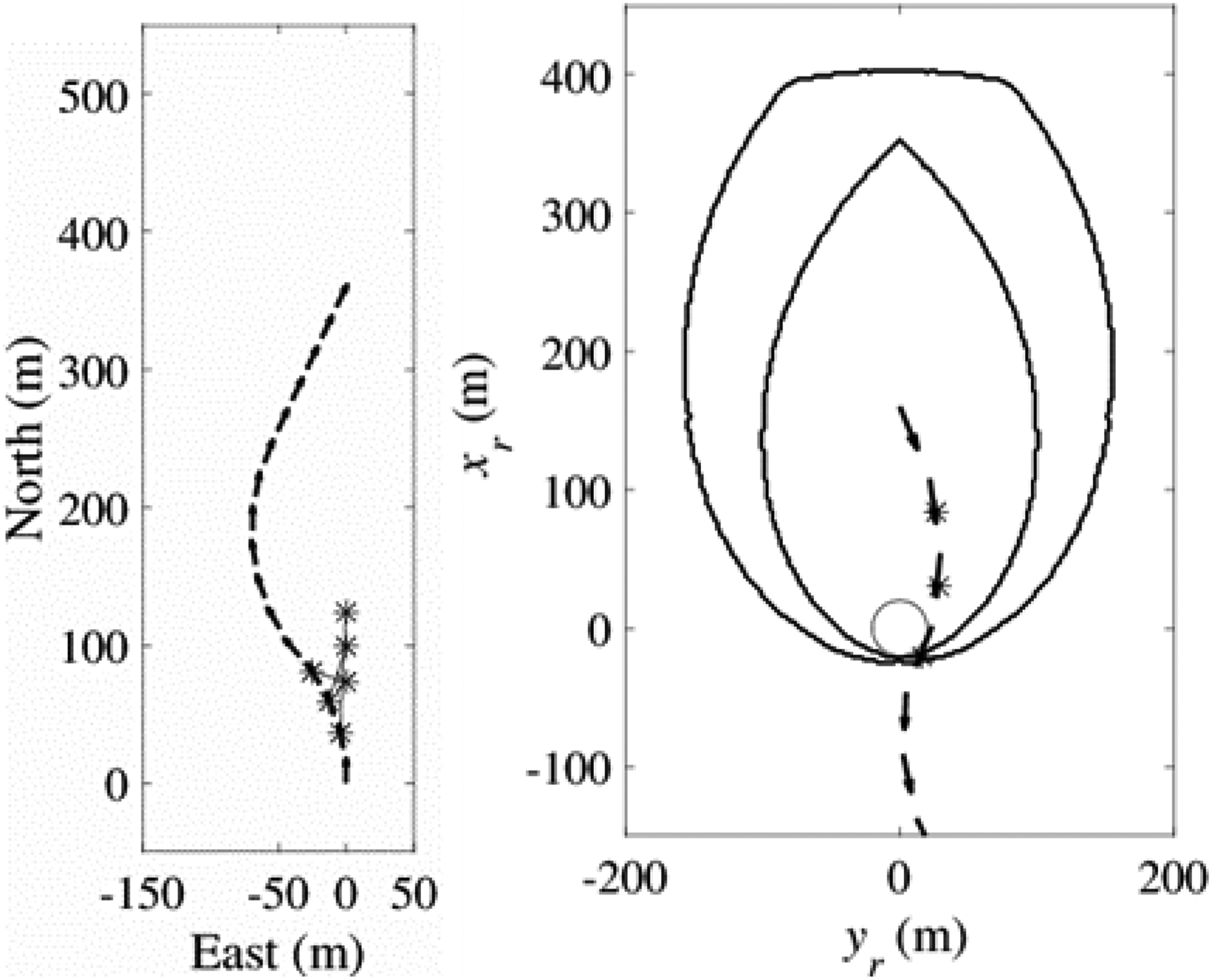
Figure 6 illustrates the action of the controller after detecting an obstacle. The controlled aircraft starts from the origin of the earth-fixed frame and is moving toward position (nd , ed ) = (650, 0). In the opposite direction, there is a moving obstacle, with velocity V max. As soon as the obstacle enters the alert zone, the collision avoidance controller overrides the LOS controller and makes the aircraft steer away from the obstacle. Whenever the obstacle returns to the safe zone, the LOS controller is given the authority to guide the aircraft. The obstacle leaves and reenters the alert zone before finally staying away from the aircraft, never reaching the danger zone.

Aircraft flying in the south-north direction (from (0,0)) meets obstacle flying in the opposite direction (starting from (no (0), eo (0)) = (400,0)) along the desired path. The stars marked in the left figure correspond to the aircraft and obstacle positions joined by segments. In the figure on the right, the same situation is shown but in local coordinates of the aircraft, and the obstacle relative trajectory is represented with arrows.
Figure 7 illustrates the conservativeness of the controller. Like before, both the aircraft and the obstacle follow opposing straight line trajectories at a constant speed V max. However, in this case, the obstacle is detected only when it is already inside the danger zone. The simulations show that in this particular instance, the aircraft is still able to avoid the obstacle. Note that this is only possible because the controller is designed for a worst-case trajectory of the obstacle.
Similar to Figure 6, but this time the obstacle is detected already inside the danger zone. However, as the obstacle is not following the worst-case trajectory, the aircraft is still able to avoid collision.
Simulation scenario 2: Bounded speed obstacles constrained to motion with bounded curvature
We now show the obtained optimal hazard levels for the case of obstacles moving in a straight line and obstacles with bounded curvature trajectories. The aircraft model parameters are the same as before.
In the first case, marked as A in Figure 8, only the obstacle speed Vo (t) and initial heading are allowed to vary, with Vo (t) ∈ [0, V max], and ωo (t) = 0 rad/s.

Hazard level as a function of obstacle position, for different classes of obstacles: in the figure of the left constrained to straight line trajectory and in the figure of the right with bounded curvature. As expected, the area of the danger and alert zones is greatly reduced when compared with Figure 5.
In the second case, the obstacle is assumed to be another fixed-wing aircraft, with angular speed given by

where φo (t) ∈ [−0.44,0.44] rad is the bank angle of the obstacle. Notice that, in this case, we explicitly consider the typical formula for banked turns, since the obstacle velocity is allowed to vary. The minimum obstacle velocity is set to V min = 15 m/s in order to mimic the stall speed of the fixed-wing aircraft.
The corresponding value functions were computed using a 251 × 161 × 73 node regular grid, with a spatial resolution of 2 m and angular resolution of 2π/72 rad. The danger and alert regions (marked as B and C in Figure 8) are projections, onto the xr–yr plane, of the actual 3-D danger and alert regions.
It can be seen that, for the more strongly constrained dynamics of the second class of obstacles (Figure 8), the area of the danger and alert zones is greatly reduced with respect to the case of obstacles with no curvature constraints (Figure 5). Additionally, for the considered scenario, the assumption of an obstacle following a straight line trajectory gives only a slight decrease of the alert and danger regions with respect to the case of obstacles consisting of fixed-wing aircrafts similar to the controlled aircraft (Figure 8). However, as the obstacle’s maximum allowed angular speed increases, the size of the danger and alert regions will increase correspondingly, converging to the shape presented in Figure 5.
Conclusions
The primary goal of this article is to present a collision avoidance system tuned for worst-case conditions that, given the assumed perception capabilities, ensures safety with respect to collisions with flying objects traveling at a same or lower speed. The system is purely reactive, in the sense that no prior knowledge regarding the obstacles flight trajectories is required.
The proposed sense and avoid system was based on a deterministic differential zero-sum game framework, which has some advantages when compared, for instance, with pure geometrical approaches, since it provides a systematic way of identifying the threat zones for any shape of the aircraft exclusion zone. This may contribute to decrease the number of deviations from the desired path when the exclusion zone is not defined as a simple circle (or cylinder, in the 3-D case). Other key advantage of the proposed approach is the low processing requirements for real-time operation, since the optimal commands for each possible relative attitude of the obstacle are computed off-line. Based on a number of tests, in simulation environments, it could be concluded that the results achieved meet the objectives of the creation of a prototype that demonstrates the utility of UAVs in patrolling the Portuguese exclusive economic zone, while promoting the UAV’s capability of performing safer flights. The tested algorithms for a collision avoidance mechanism can be translated into a fundamental contribution for the development of capabilities required by two types of missions—search and rescue, and maritime surveillance—thus providing an increase in maritime situational awareness and reducing the operating costs of such missions through the removal of the human element from the maritime environment.
Footnotes
Declaration of conflicting interests
The author(s) declared no potential conflicts of interest with respect to the research, authorship, and/or publication of this article.
Funding
The author(s) disclosed receipt of the following financial support for the research, authorship, and/or publication of this article: This work was funded by POFC (Programa Operacional Factores de Competitividade) within the National Strategic Reference Framework (QREN) under grant agreement 2013/034063 (SEAGULL, project number 34063).