
Abstract
As to the complicated terrain in forest, forestry chassis with an articulated body with three degrees of freedom and installed luffing wheel-legs (FC-3DOF&LW) is a novel chassis that can surmount obstacles. In addition, the rear frame of FC-3DOF&LW is regarded as the platform to carry equipment. Small inclination angle for rear frame contributes to stability and ride comfort. This article describes the strategy of traversing obstacles and simulation for FC-3DOF&LW that drives in forest terrain. First, key structures of FC-3DOF&LW are briefly introduced, which include articulated structure with three degrees of freedom and luffing wheel-leg. Based on the sketch of luffing wheel-leg, the movement range of luffing wheel-leg is obtained by hydraulic cylinder operation. Second, the strategy of crossing obstacles that are simplified three models of terrain is presented, and the simulation for surmounting obstacles is constructed in multibody dynamics software. The simulation results demonstrate that the inclination angle of rear frame is 18° when slope is 30°. A maximum 12° decrease of inclination angle for rear frame can be acquired when luffing wheel-legs are applied. For traversing obstacles with both sides, the maximum inclination angle of rear frame is about 1.2° and is only 3° for traversing obstacles with single side.
Introduction
Forestry vehicles are perceptive machines that can be used to perform a variety of forestry tasks including felling, delimbing, harvesting, and transporting logs. Especially, along with the improvement of work efficiency and safety, the mechanization of forestry operations is particularly important in recent years. 1 –3 However, half of the earth surface, and also half of the forest area, is not accessible by conventional wheeled vehicles. There is, thus, a large engineering challenge to increase the mobility and trafficability performance of forestry chassis. As a result, the development of the off-road chassis has received increasing interest and has been widely pursued by researchers. 4 –8
Currently, forestry vehicles can be roughly divided into two types of chassis: tracked and wheeled. Meanwhile, legged and wheel-legged are also regarded as wheeled structure. 9 For the tracked chassis development, a lot of researches can be found. A new design for a tracked forestry machine bogie (long track bogie) on soft and rough terrain is investigated using nonsmooth multibody dynamics simulation by Edlund et al. Bogies increase the traction and stability by basically maintaining the contact between the rough terrain and wheels. In addition, to increase the ground contact area and the traction, tracks are used over the bogie wheels. As a result, the tracked bogie was shown to have higher mobility. 10 Liu et al. proposed a novel agricultural driving chassis that can operate via four groups of tracked driving device with planetary structure (TDDPS). The novel TDDPS presented adaptive terrain capacity and overcomes the obstacles by turnover. The chassis had excellent off-road abilities, which can run and work in rough agricultural terrain. 11 In the process of surmounting obstacles, the structure of swing arms can adjust the position of chassis, which contribute to climbing obstacles. Four-track robot with two swing arms is developed to surmount obstacles by Li et al. The motion mechanism and maximal obstacle-surmounting capacity of step-climbing forward and backward are mainly analyzed. 12 Tracked chassis have good tractive and stability performance, which are generally applied in uneven terrain. A detailed multibody model for the dynamic simulation of off-road tracked vehicles was proposed by Rubinstein and Hitron and developed using the LMS-DADS simulation program. 13 Omnidirectional vehicles have much higher maneuverability than common vehicles, and tracked vehicles have superior cross-country capacity compared to wheeled vehicles. Therefore, a tracked omnidirectional and cross-country vehicle was designed by Zhang and Huang. The innovational track chassis demonstrates omnidirectional motion on uneven terrains, superior steering efficiency, and comparable cross-country performance in comparison to conventional tracked vehicles. 14 Tracked chassis, in general, have a larger ground contact area, and consequently, they give a lower ground pressure than wheeled chassis. They also have good tractive and stability performance. However, drawbacks of a tracked chassis are inevitable. Tracked chassis cause large shearing of the ground, especially when operating in rough terrain when changing the driving direction. In addition, vehicles with tracked chassis cause significant damage to the soil and surrounding plants when they run in forest.
Conventional wheeled vehicles have serious mobility limitations in rough terrain, despite higher operation efficiency and less damage to the soil in forest. Hence, legged and wheel-legged structures are proposed in numerous study developments. A six-legged robot to surmount obstacles is analyzed by Sorin and Nitulescu. Meanwhile, the geometrical model for the leg is developed using Denavit–Hartenberg algorithm. 6 Stability for multilegged structure is crucial, which effects the performance of surmounting obstacles. Shekhar and Kumar established the dynamic model of six-legged walking robot and made an analysis of stability and energy consumption. 15 Stability based on foot force margin for multilegged robots is presented by Agheli and Nestinger. A force-based stability margin that utilizes measured contact normal foot forces as the stability metric simplifies data and computational requirements. 16 However, legged chassis has a high number of degrees of freedom and actuators and thus has a tendency to have high energy losses and also a high control complexity that limits its mobility in rough terrain. Moreover, a large number of actuators and sensors make it expensive, potentially unreliable, and also economically unfeasible. 17
Wheel-legged chassis contribute to improving mobility and trafficability performance and have small damage to the surrounding environment. As a result, they are widely applied in different fields including the terrain in forest. 18 Bogies are generally regarded as wheel-legged mechanisms that are applied in vehicles to ensure the even contact of the wheels on uneven terrain. The studies performed by Roca et al. and Comellas et al. quantified the ability of overcoming obstacles by using different configurations of vehicle with bogies. 17,19 Bogies are robust, but their main drawback is their heavy weight. In addition, bogies combined with articulated steering create severe shearing of the soil when turning. 9 Sun et al. designed a new type of transformable wheel-legged mobile robot that could be applied on both flat and rugged terrains. The obstacle climbing strategies under wheeled and legged modes are also obtained. 20 The structure of wheel-legged is used in a small robot, which is significant to develop in forestry chassis. Sun and Liu introduced a new luffing wheel-legged robot with six legs. 21 The design aims at carrying working equipment and surmounting obstacles actively on forest roads. However, the complexity of construction and control, given the coordinated simultaneous wheel-leg movement for the advancement of the vehicle, quickly led to problems such as low efficiency for surmounting obstacles. In general, quadruped eccentric wheels are also considered as wheel-legged structure. A model of a quadruped eccentric wheel chassis is proposed by Ge and Wang, which achieved excellent performance when crossing obstacles, even exhibiting the ability to climb stairs. 22 Although the chassis-installed quadruple eccentric wheel enhances the trafficability, vehicle ride comfort is sacrificed. Meanwhile, the low speed of the chassis, which was caused by installing quadruped eccentric wheel-leg, had an effect on driving efficiency on flat roads. Zhu and Kan proposed a forestry chassis with an articulated body with three degrees of freedom (FC-3DOF). 23 The six-wheel-driven articulated chassis adopting the principle of adapting to terrain is designed with three degrees of freedom. As a result, the chassis with an articulated body with three degrees of freedom has good adaptability to the terrain, good trafficability, and flexible steering ability compared with conventional six-wheeled chassis. However, poor ride comfort for chassis is presented when crossing obstacles with both sides. Based on the issue above, a novel chassis with an articulated body with three degrees of freedom and installed luffing wheel-legs (FC-3DOF&LW) is designed. Ride comfort of chassis is analyzed by luffing wheel-legs control when crossing obstacles with both sides. 24 However, the conditions of forestry terrain are complicated. FC-3DOF&LW carried operation equipment in rear frame drives in forestry terrain. The unique consideration of crossing obstacles with both sides is insufficient. Other conditions of terrain also need to be considered. Hence, the strategy of traversing obstacles based on terrain should be analyzed in detail. In addition, the rear frame of FC-3DOF&LW is regarded as the platform to carry equipment. Therefore, small inclination angle for rear frame contributes to stability and ride comfort. In summary, the issues above are considered in this article. According to hydraulic cylinder operation, the movement range of luffing wheel is obtained. A maximum 12° decrease of inclination angle for rear frame can be acquired when chassis climbs slope. Importantly, the strategy of traversing obstacles that are simplified three models of terrain is presented, and the simulation for surmounting obstacles is constructed in multibody dynamics software. As a result, for climbing slope, the inclination angle of rear frame is 18° when slope is 30°. For traversing obstacles with both sides, the maximum inclination angle of rear frame is about 1.2° and is only 3° for traversing obstacles with single side.
Design of FC-3DOF&LW
Concept design
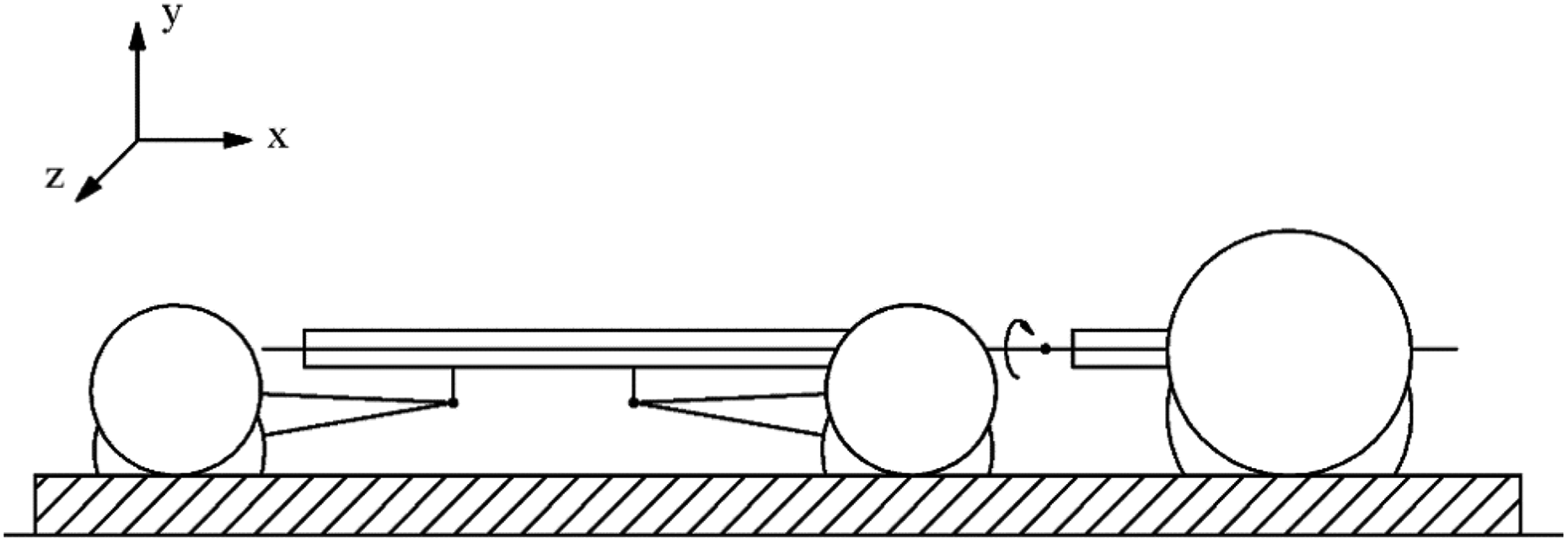
FC-3DOF&LW is proposed to surmount rough terrain in the forest as Figure 1. It consists of two frames, two front wheels and four luffing wheel-legs. The two frames are connected by an articulated structure with three degrees of freedom. Importantly, the four rear wheel-legs with a luffing function are attached to the rear frame and distributed on both sides symmetrically, each with a wheel in the end. In this design, key body structures of FC-3DOF&LW include articulated structure with three degrees of freedom and luffing wheel-leg. Especially, articulated structure contributes to enhance the capacity to traverse obstacles, and the structure of luffing wheel-legs ensures smooth obstacle-surmounting.

Structure of the FC-3DOF&LW: (1) Front frame, (2) power train, (3) rear frame, (4) luffing wheel-leg, and (5) articulated structure. FC-3DOF&LW: forestry chassis with an articulated body with three degrees of freedom and installed luffing wheel-legs.
Articulated structure with three degrees of freedom
Articulated structure is a mechanism that is often applied in engineering vehicle to make a turn. The characteristic of a small radius of steering is suitable for working in forests. However, traditional articulate structure is difficult to adapt to complex terrain in forest. Based on the reason above, a novel structure is proposed. Articulated structure with three degrees of freedom is shown in Figure 2, which can roll in three directions (x, y, and z directions). The articulated structure with three degrees of freedom is a passive mechanism, which contributes to enhance the capacity to adapt to terrain and ensures full-time contact between wheels and ground for driving in a complex road environment.

Articulated structure with three degrees of freedom: (1) stop block 1, (2) articulated joint pin, (3) stop rear cover, (4) bolt, (5) cover plate (up), (6) Belleville spring, (7) Rear frame, (8) link span, (9) hydraulic cylinder, (10) cover plate (down), (11) stop block 2, (12) articulation yoke, (13) connecting pin, and (14) front frame.
Luffing wheel-leg
This luffing wheel-leg is an active piece of equipment that consists of six parts, which achieves two working modes. As shown in Figure 3, the wheel-leg will lift when lifting hydraulic cylinder 3 shortens and will drop when dropping hydraulic cylinder 6 elongates. With uncoupled motion, it is convenient to control the position of the wheels. Therefore, the luffing wheel-leg could match with articulated body with three degrees of freedom, which enhances the ability to run in forestry terrain.

Structure of the luffing wheel-leg: (1) Pendulum arm, (2) fixed structure, (3) lifting hydraulic cylinder, (4) joint structure, (5) rotary structure, and (6) dropping hydraulic cylinder.
Motion analysis
Motion analysis of luffing wheel-leg
The position of luffing wheel-leg affects the performance when FC-3DOF&LW run in uneven road. A simplified model that presents two working conditions is shown in Figures 4 and 5. Separately, Figure 4 presents the luffing wheel-leg with lifting, and Figure 5 presents the luffing wheel-leg with dropping. The related parameters are shown in Table 1.

Sketch of luffing wheel-leg with lifting.
Sketch of luffing wheel-leg with dropping.
Initial parameters of the luffing wheel-leg.

According to Figure 4, the range of point F that presents the position of wheel-leg can be acquired. Especially, point O is the origin of coordinates, and


As a result


By using equations (7) and (8), the ranges of point F′ in x- and y-axis directions are shown in Figure 6. It is known from Figure 6(a) that the variation of point F′ in x direction is from 901 mm to 912 mm with the operation of luffing hydraulic cylinder. For y direction, the variation of point F′ is from 244 mm to 78 mm (shown in Figure 6(b)).

The curve between point F and lifting hydraulic cylinder.
The other condition of luffing wheel-leg with a downward motion is presented in Figure 5. In contrast, the pendulum arm 1 has a rotation of δ when dropping hydraulic cylinder 6 elongates. Point F of the wheel-leg moves to point F″, which can be expressed in x- and y-axis directions as follows


As a result


Similarly, by using equations (11) and (12), the ranges of point F″ in x and y directions are shown in Figure 7. It is known from Figure 7(a) that the variation of point F″ in x direction is from 901 mm to 813 mm with the operation of luffing hydraulic cylinder. For y direction, the variation of point F″ is from 244 mm to 488 mm (shown in Figure 7(b)).

The curve between point F and dropping hydraulic cylinder.
Motion analysis of front frame
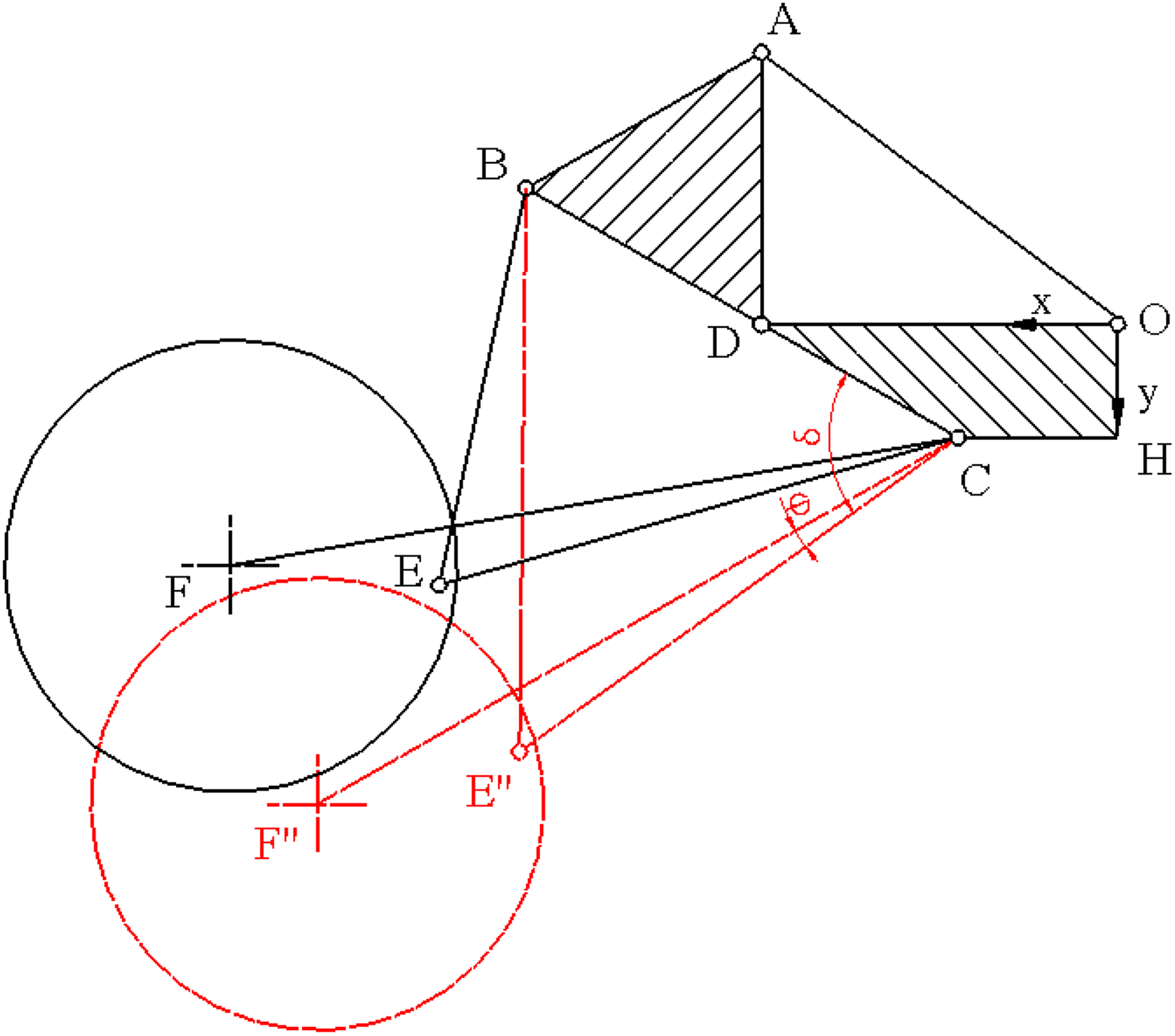
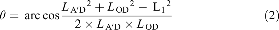
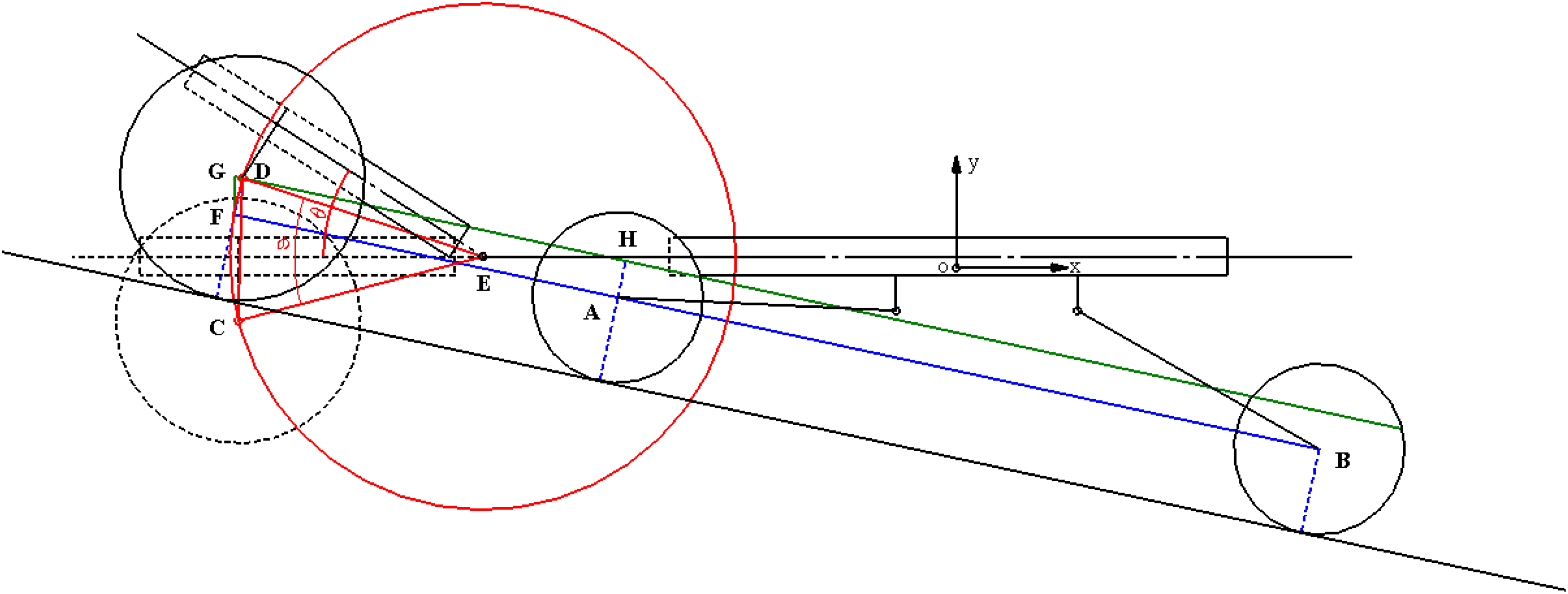
The range of wheel-leg can be obtained by the above analyses. A limited angle that occurred between front luffing wheel-legs and rear wheel-legs is 12°. Meanwhile, front wheel-legs in y direction is 78 mm, and rear wheel-legs in y direction is 488 mm (shown in Figure 8). Hence, two conditions of climbing slope are separately considered. The rear frame is still horizontal to climb slope when slope is less than 12°. On the other hand, when slope is over 12°, a 12° decrease of inclination angle for rear frame is provided. In addition, inclination angle of front frame around articulated structure (point E) occurs when luffing wheel-legs in rear frame reach the limited position for climbing slope (shown in Figure 8). The related parameters are shown in Table 2, and the inclination angle of front frame can be obtained as follows (point O is the origin of coordinates, and
Sketch of climbing slope for FC-3DOF&LW. FC-3DOF&LW: forestry chassis with an articulated body with three degrees of freedom and installed luffing wheel-legs.
Initial parameters of the chassis structure.

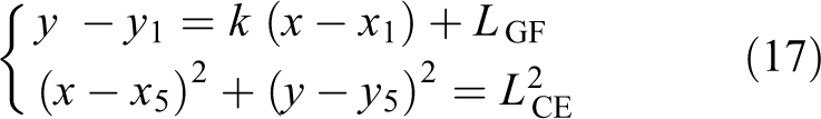
The line AB equation can be expressed as follows

The line DH equation can be expressed as follows

The circle equation of point E that is regarded as the center can be expressed as follows

Therefore, coordinate of point D can be obtained
According to the condition of front frame, constraint of D (

Hence, D1 (−1921, 244) or D2 (−598, −44) (rejection)


As a result, θ = φ = 33°.
The above analyses mean that a 33° inclination angle of front frame compared with rear frame is formed when luffing wheel-legs keep the posture of climbing slope.
Strategy of traversing obstacle
Analysis of traversing obstacle
FC-3DOF&LW is proposed to run in the forest. Unstructured road in the forest creates the biggest challenge for forestry chassis. FC-3DOF&LW compared with conventional chassis needs to overcome extreme obstacles and shows good performance to surmounting obstacles. Generally, extreme obstacles include three conditions in the forest. The first condition is climbing slope, and the second condition is traversing obstacles with both sides. The rest is traversing obstacles with single side.
The condition of climbing slope
Two conditions to climb slope are considered. Based on the movement of luffing wheel-legs, the rear frame is horizontal to climb slope when slope is less than 12° (shown in Figure 9(a)). The other situation is a maximum 12° decrease of inclination angle for rear frame when slope is over 12° (shown in Figure 9(b)). To decrease the rotated angle between front frame and rear frame, four luffing wheel-legs move down synchronously when front frame climbs slope. Then, two front wheel-legs move up when they prepare to climb slope. Meanwhile, two rear wheel-legs keep moving down until limited position. As a result, a reduced inclination angle for rear frame that often carries equipment contributes to keeping stability when chassis climbs slope.

Sketch of climbing slope: (a) climbing 12° slope and (b) climbing 30° slope.
The condition of traversing obstacles with both sides
Combining with the luffing wheel-legs operation, the overall process for FC-3DOF&LW to overcome obstacles with both sides is as follows. (1) Four luffing wheel-legs descend to match with front frame when front frame surmounts obstacle. With the process, “b” is equal to the sum of “a” and the height of obstacle. (2) Front luffing wheel-legs of rear frame raise when wheel-legs encounter obstacle. (3) Rear luffing wheel-legs of rear frame raise when wheel-legs encounter obstacle (shown in Figure 10).

Sketch of traversing obstacles with both sides.
The condition of traversing obstacles with single side
For traversing obstacles with single side, the front frame has a twist that can be operated by articulated structure with three degrees of freedom around x direction. Four luffing wheel-legs start to descend when front frame surmounts obstacle. With wheel-legs descending, rear frame raises in y direction, which contributes to the twist around x direction for front frame. In addition, two luffing wheel-legs that are installed on the side of obstacle separately raise when obstacle needs to be surmounted by them. The process of traversing obstacle with single side can make sure that rear frame is always horizontal, and the articulated structure with three degrees of freedom contributes to reducing the effect that is caused by the twist of front frame on rear frame (shown in Figure 11).
Sketch of traversing obstacles with single side.
Simulation experiments and results analysis
Establishment of the simulation
In order to verify the effectiveness of the novel FC-3DOF&LW, the virtual prototype of FC-3DOF&LW is established in SolidWorks, and simulations are carried out in ADAMS that is applied in multibody dynamics simulation. Three conditions that include the process of climbing slope, traversing obstacles with both sides, and traversing obstacles with single side are considered to describe the strategy of crossing obstacle. In simulation process, the initial velocity of FC-3DOF&LW is 2 m/s, and the basic parameters are shown in Table 3. Tires of chassis are based on Fiala model, and the parameters are shown in Table 4.
Basic parameters of the FC-3DOF&LW in simulation.

FC-3DOF&LW: forestry chassis with an articulated body with three degrees of freedom and installed luffing wheel-legs.
Parameters of tires.

The simulation of climbing slope
To describe the process of climbing slope, a 30° slope that is regarded as limited slope is built in ADAMS. The process of climbing slope is divided into two active controls. First, as to the novel articulated structure with three degrees of freedom, rotated angle between front frame and rear frame is formed when front frame starts to climb slope and will increase with front frame moving. As a result, to decrease the rotated angle, four luffing wheel-legs move down synchronously when front frame climbs slope (shown in Figure 12(b)). Second, two front wheel-legs move up when they prepare to climb slope. Meanwhile, two rear wheel-legs keep moving down (shown in Figure 12(c)). Eventually, the chassis adopt the status to climb slope when luffing wheel-legs reach limited positions (shown in Figure 12(d)).

Simulation of climbing slope process: (a) initial status with the whole chassis, (b) climbing slope with front frame, (c) climbing slope with rear frame, and (d) climbing slope with the whole chassis.
The simulation of traversing obstacles with both sides
The lifting of luffing wheel-legs in vertical direction is 160 mm (shown in Figure 6(b)). Therefore, due to the limitation, the height of surmounting obstacle for the chassis is less 160 mm. As a result, for traversing obstacle with both sides, a 160-mm tall obstacle is built in ADAMS. The process of traversing obstacles with both sides is divided into three active controls. Four luffing wheel-legs lift synchronously when front frame surmounts the obstacle, which makes sure that front frame traverses obstacle smoothly (shown in Figure 13(a)). In addition, to surmount the obstacle for the rear frame, wheel-legs of rear frame must respectively lift. One is the lifting for the two wheel-legs in the front of the rear frame, and the other is the lifting for the rear of the rear frame (shown in Figure 13(b) and (c)).

Simulation of traversing obstacles with both sides: (a) surmounting obstacle for front frame, (b) surmounting obstacle for front wheel-legs in rear frame, and (c) surmounting obstacle for rear wheel-legs in rear frame.
The simulation of traversing obstacles with single side
Another condition for traversing obstacles with single side is presented in ADAMS. A 160-mm obstacle is built in one side of chassis. As to the novel articulated structure, a twist between front frame and rear frame can be achieved around driving direction. In the process, four luffing wheel-legs lift synchronously to eliminate height difference that is caused by front frame raise when front frame surmounts the obstacle with single side (shown in Figure 14(a)). With the movement, wheel-legs of rear frame installed in one side are respective lifting when they reach obstacle (shown in Figure 14(b) and (c)). As a result, FC-3DOF&LW traverses obstacles with single side smoothly.

Simulation of traversing obstacles with single side: (a) surmounting obstacle for front frame, (b) surmounting obstacle for the first wheel-leg in one side of rear frame, and (c) surmounting obstacle for the second wheel-leg in one side of rear frame.
Discussion of the simulation results
The simulation results of three conditions are analyzed separately. For climbing slope, front frame connects with articulated structure through articulated joint which is shown in Figure 15. The rotation angle of the articulated joint is shown in Figure 16. Climbing slope by front frame occurs at 1.9 s and by the whole chassis at 4.3 s. Articulated joint angle is increasing because of front frame climbing. Meanwhile, the angle is decreasing when rear frame starts to climb slope. In this process, as to the operation of luffing wheel-legs, the maximum angle is only 31° during 1.9–4.3 s. In addition, to reduce the inclination of rear frame, two front wheel-legs in rear frame move up until limited positions, and two rear wheel-legs move in the opposite direction during 4.3–5 s. As a result, the angle reaches 33°, which is consistent with the theoretical model in the “Motion analysis of front frame” section.

Schematic diagram of the articulated joint.

The rotation angle of articulated joint.
The inclination angle of rear frame is shown in Figure 17. The rear frame starts to climb slope at 3.1 s, and the inclination angle is increasing until 4.3 s. Although the inclination angle is less than 30°, the maximum value reaches 25°, which is not conducive to the chassis climb slope. Meanwhile, four wheel-legs continue moving to limited position, and the inclination angle of rear frame is decreasing. Eventually, an 18° inclination angle of rear frame is obtained. According to the results in the “Motion analysis of front frame” section, a 12° inclination angle between front wheel-legs and rear wheel-legs can be acquired. Hence, the inclination angle of rear frame is only 18° when FC-3DOF&LW runs in the slope of 30°. This means that the process of climbing slope contributes to keeping work platform stable for carrying equipment.

The inclination angle of rear frame.
For traversing obstacles with both sides, the angle variation of articulated joint is shown in Figure 18. Based on curves, the maximum angle is only 4°. Especially, Figure 19 shows the inclination angle of front frame, and Figure 20 shows the inclination of rear frame. In Figure 19, the chassis starts to surmount obstacle at 1.5 s, and the maximum inclination angle of front frame is less than 4° when chassis surmounts obstacle. Meanwhile, the maximum inclination angle of rear frame is 1.2° that is shown in Figure 20. It means that frames can almost be horizontal when chassis traverse a 160-mm tall obstacle.

Articulated joint angle for FC-3DOF&LW. FC-3DOF&LW: forestry chassis with an articulated body with three degrees of freedom and installed luffing wheel-legs.
The inclination angle of front frame.
The inclination angle of rear frame.
Curves of barycenter displacement for the front and rear frames are shown in Figure 21. Based on curves, surmounting the obstacle by front frame occurs at approximately 1.5–2.1 s and by rear frame at approximately 2.5–5 s. Curves of barycenter displacement between front and rear frames are well matched, indicating that they provide a smooth drive for traversing obstacles with both sides.
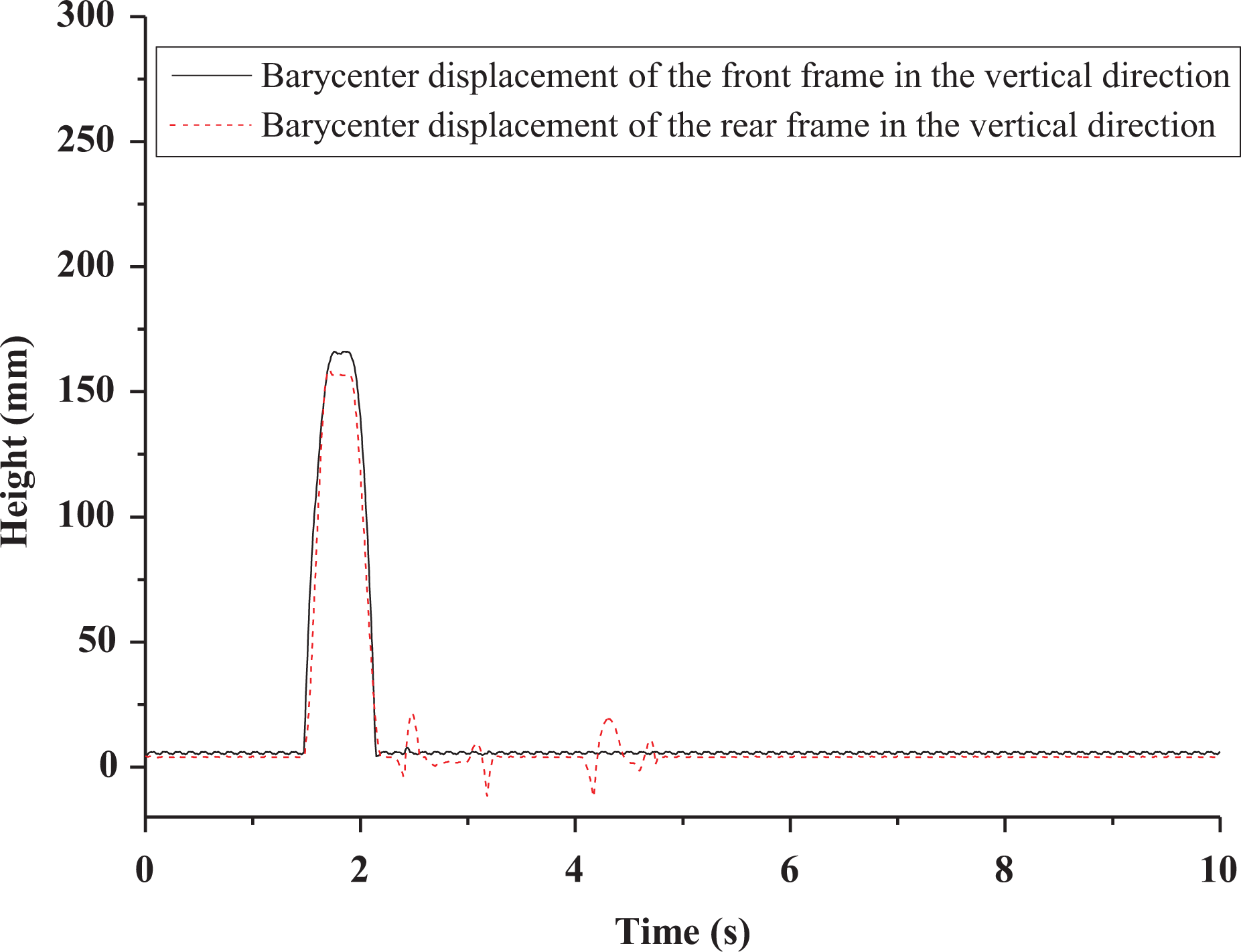
Curves of barycenter displacement for FC-3DOF&LW. FC-3DOF&LW: forestry chassis with an articulated body with three degrees of freedom and installed luffing wheel-legs.
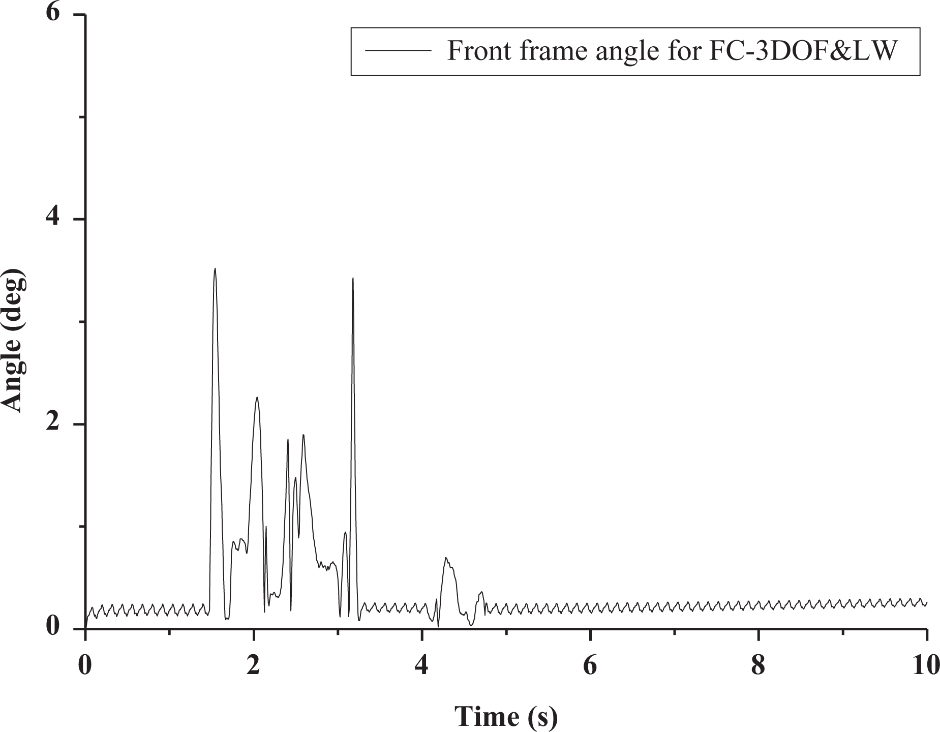
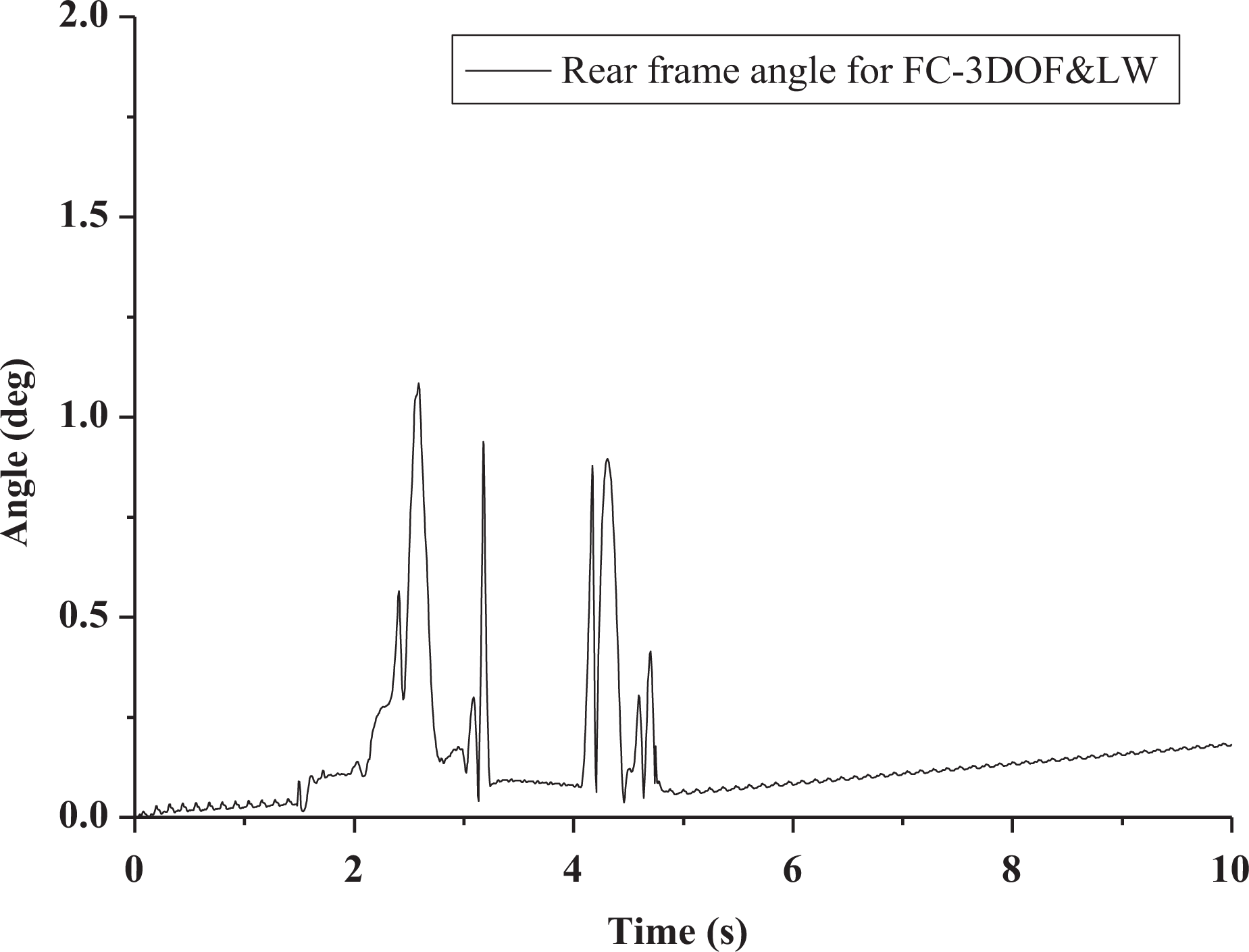
For traversing obstacles with single side, similar condition can be seen in Figures 22 and 23. In Figure 22, a twist angle of front frame is shown. Based on the curves, the twist angle is about 7° for traversing obstacle with single side. However, the value of twist angle reaches 9° when the process is at 2 s. As a result, the reason for the twist angle increase at 2 s is likely to be the front wheel-leg in one side of rear frame operation to adapt to change in the terrain while surmounting the obstacle. In addition, the maximum inclination angle of rear frame is only 3°, which can be regarded as horizontal to surmount obstacle in Figure 23. Therefore, the combined effect of articulated structure and the luffing wheel-legs enhances the chassis performance to traverse obstacles with single side.

Front frame twist angle for FC-3DOF&LW. FC-3DOF&LW: forestry chassis with an articulated body with three degrees of freedom and installed luffing wheel-legs.

The inclination angle of rear frame.
Conclusion
FC-3DOF&LW is proposed as a chassis which drives in forest terrain. In this article, key structures of FC-3DOF&LW are introduced, which include articulated structure with three degrees of freedom and luffing wheel-leg. Especially, the motion of luffing wheel-leg is analyzed, and the movement range is calculated. Based on the above analysis, the maximum inclination angle of rear frame is obtained when luffing wheel-legs move to limited position individually. Meanwhile, three simplified terrain conditions for surmounting are constructed, and the strategy of surmounting obstacles for FC-3DOF&LW is proposed. To verify the analysis exactly, simulations that surmount simplified terrain are established in ADAMS. As a result, for climbing a 30° slope, a maximum 12° decrease of inclination angle for rear frame can be acquired when luffing wheel-legs are applied. For traversing obstacles with both sides, the maximum inclination angle of rear frame is about 1.2° and is only 3° for traversing obstacles with single side. Simulation results validate the effectiveness of the proposed forestry chassis.
Footnotes
Declaration of conflicting interests
The author(s) declared no potential conflicts of interest with respect to the research, authorship, and/or publication of this article.
Funding
The author(s) disclosed receipt of the following financial support for the research, authorship, and/or publication of this article: This work was supported by the Fundamental Research Funds for the Central Universities (Grant No. 2015ZCQ-GX-01) and Beijing municipal construction project special fund.