
Abstract
This article deals with fault isolation issue for the redundant thrusters of frame-structure unmanned underwater vehicles (UUVs). Consistency check is adopted to accomplish this task while solving the reformed control input equations that are produced after getting rid of some fault-free terms from the given equations. Specially selected column vectors from the given control matrix together with the corresponding hypothetical thrust output faults are taken as the known/unknown elements for these equations. Redundant relations among the thrusters support the vector selection, which are revealed by analyzing the maximally linearly independent vectors of the given control matrix. Simulation with faulty thrusters under redundancy in a frame-structure unmanned underwater vehicle illustrates the effectiveness of the proposed methodologies.
Introduction
Unmanned underwater vehicle (UUV) has been part of the currently researched emphases, with which the human beings could explore and exploit resources under the sea more conveniently. 1 However, the watery undersurface environment obstructs UUVs to carry out tasks freely and might induce faults on the working actuators. Fault diagnosis (FD) is a rigorous way to get the faulty situations on a UUV and would provide early and exact fault information. 2 Thus effective fault-tolerant control strategies could be designed for the safety assurance. 3,4
FD contains the processes of fault detection, isolation, and identification, where different levels of fault information are generated. Fault isolation (FI) is used to locate the most possible place of the fault that has occurred on the object. Many research studies have concerned about this problem. 5 –7 In current research issues, FI is tied up with fault detection, where once the relative fault parameters are estimated, the faults are detected and isolated. Because the correspondence between the estimable fault parameter and the actual faulty object is exclusive. For example, Zhang et al. dealt with the UUV thruster FD while the UUV is not configured over-actuated, that is, there is no extra thruster, and the FI is straightly achieved based on unambiguous and exclusive mapping between the estimated parameters and the faulty thrusters. 8
Actuators/sensors are usually deployed under redundancies, thus the correspondence between the estimable parameter that presents the fault and the actually faulty object might not be exclusive. Hardware and analytical redundancies are two choices to provide actuators/sensors and analytical models as redundancies for the researched objects. They could be used for FI by comparing readings between the provided redundancies and the researched objects. 9 The redundant relations among the researched objects and the hardware/analytical redundancies are set up in advance, but they only include the actively added ones used for FD. Series of observers are usually adopted in parallel for this issue to estimate and isolate the fault, and each one is against an estimable fault parameter corresponding to one object that might be a redundancy. 10 –12 The problem is that the redundant relations among the objects have not been analyzed, thus the fault might be difficult to distinguish.
While the corresponding relationships among the estimated parameters and the faulty objects are not exclusive, Willersrud et al. builds a series of fault residuals of which each has or has not a specific relation with all the given faults of the operations, and thus a dependency table is generated to isolate the faults by comparing its signatures. 13 It tries to find ways of distinguishing the faults among the redundant elements; however, the redundant relations are not apparent and only one fault is assumed to act on the system at a given time instant.
Since actuators (especially the thrusters) of a UUV guide its movements, the faulty ones are necessary to be isolated. This article focuses on the FI issue against the redundant thrusters of the frame-structure UUVs, while some of the redundant thrusters may have got into faulty simultaneously and only the sailing velocity, position, and attitude outputs can be collected. A methodology based on solving reformed control input equations could effectively give the FI results.
As the given control matrix in the control input equations includes the deploying relations among all the thrusters, the analysis against this matrix is carried out to look for special thruster sets that have no redundant relation, however, may contain all the faulty thrusters. With special elimination, the given control input equations are reformed to contain only a set of chosen thrusters, and a redundant equation exists in each subset of control input equations corresponding to a destroyed redundant relation, which could produce an error equation. Consistency check can be carried out through checking all these errors from the error equations, 14,15 where the chosen set coincided with 0 error all the time contains all the faulty thrusters, and the corresponding reformed control equations will present these thrusters and fault magnitude.
The remainder of this article is organized as follows: the second section gives the preliminary support for the following researches; the third section displays the main results including the redundancy analysis and FI; the fourth section posts a simulation on a frame-structure UUV to illustrate the effectiveness of the given methodologies; and the fifth section concludes this article.
Preliminaries and problem statement
The control input equation of the UUVs is usually expressed as 16

where τ is the output vector of equation (1) and also the model control input vector of forces and moments for the dynamics system; B represents the control matrix that contains the deploying relations among all the thrusters; and
Figure 1 displays the frame of a frame-structure UUV configured with m thrusters among which the thruster vT is a vector and sT is a fixed one. The details of B and


where

Frame of a frame-structure UUV. UUV: unmanned underwater vehicle.
Usually, the input

where
If the frame-structure UUV is configured with redundant thrusters, the fault can hardly be diagnosed directly while
Lemma 1
Consider control matrix
Lemma 1 indicates that the redundant relations among the thrusters are contained in control matrix B. A definition is given below for the subsequent analyses:
Definition 1
SmaxLIV is defined as a set of r maximally linearly independent column vectors from a given matrix B.
Definition 1 interprets that these r vectors are linearly independent; however, any r + 1 column vector from B are linearly dependent. Thus, any column vector of B could be represented by linearly combing the r vectors of SmaxLIV. The linear combination can be regarded as a redundancy of the former one and could replace it in some applications. With this analysis, the redundant relations in control matrix B might be got by finding the corresponding SmaxLIV.
Suppose that
Solution of SmaxLIV

With SmaxLIV, the redundancy relations and the probable combinations of faulty thrusters are hopeful to be discovered, which could help to reveal the FI issue through solving some equations.
Main results
This section will give the main methodology for isolating the faulty thrusters. Since redundant thrusters are usually mounted on a frame-structure UUV to make it over-actuated, it is necessary to clarify the redundant relations among the working thrusters for FI.
Redundancy analysis
Equation (1) transforms
Definition 1 manifests that if a column vector

where k is a serial number and k1, k2,….., and kr are column numbers, then

where coefficients uj and
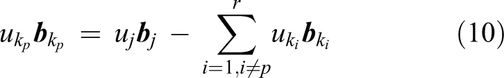
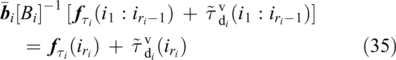
So
A theorem is necessary to be displayed for analyzing the redundant relation between any two groups of thrusters on the basis of the aforementioned inference. Take any two groups of thrusters that are labeled as v and w with respective mv and mw thrusters. The output forces and moments provided by these thrusters are assumed to be
Theorem 1
If there’s an SmaxLIVk of B that satisfies

where
Proof
Suppose that SmaxLIVk in equation (11) has been found by using Algorithm 1. Being similar to equation (9), it is clear that

where
Adding up equation (12) for all j generates

where
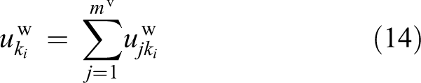
Thus,

where
Using Theorem 1, the redundant relations of all the thrusters deployed on a frame-structure UUV can be clarified.
Algorithm 1 helps to find all SmaxLIV of B. However, some local SmaxLIV might exist, where the column vectors of different local SmaxLIV are linearly independent, that is, they have no redundant relation with each other. For example, let
Solution of local SmaxLIV

Proof
To find local SmaxLIV, the local redundant relations are necessary to be confirmed as the given SmaxLIV cannot make a redundant relation alone. Thus, matrices S and R are firstly set up to contribute column vectors jointly for constructing redundant relation.
Steps (1), (2), and (3) produce all the redundant relations; and step (4) combines the relations that have common column vectors. As the former three steps are apparent, only step (4) is necessary to be proved. Suppose there are two different redundant relation sets
Choose SmaxLIV of Sv as


where uv, uw,

Equation (18) indicates that the randomly picked vector
Because the deduced redundant relation is related to the vectors of both former sets, it is necessary to merge the sets that have common column vectors. If the redundant relation sets have more than one common column vectors, similar processes could be deduced to get the same conclusion. Apparently, while any two local redundant relation sets have no common column vector, they cannot be merged.
The proof is completed.
The rest vectors of S do not constitute any local redundant relation with any vector of R, which are all independent and called individual vectors. With local SmaxLIV and individual vectors, the following subsection will display the deduction of FI methodology.
Fault isolation
To diagnose thruster faults, fault detection is usually used firstly to generate estimates of predefined fault parameters, after which FI is utilized to produce more accurate fault information for the fault-tolerant control. This subsection will figure out the FI issue on the basis of the stage that the additive output fault
As the mounted thrusters are not far away from each other restricted to UUV size, and the ones contained in the same redundant relation could all have fault suspicion, it could image that each thruster in the same redundant relation bears the similar fault risk. Then, some assumptions are prepared.
Assumption 1
The disturbance is negligible.
The main job of this article is to reveal the information that hides in equation (1); however, the parameter estimation and fault-tolerant control are not included, so the disturbance related to those two steps is not considered temporarily.
Assumption 2
The redundant relation of two thrusters is nonexistent, that is
If the redundant relation is supposed to exist, k is ±1 based on equation (2). Thus, these two thrusters are placed in line with the same thrust direction or with the opposite thrust direction but the line passes through the buoyant centre. These two thruster deployments are a little inappropriate.
Assumption 3
The thruster fault is considered to behave on thrust magnitude and/or thrust direction only if the thruster is a vector.
To simplify and concentrate on the present preliminary issue, more complicated forms of faults are not included.
With these assumptions, a proposition is produced.
Proposition 1
The thrusters corresponding to the column vectors of an SmaxLIV will not get out of order simultaneously.
Proof
Restricting to the actual UUV size, the thrusters are mounted not far away from each other. The ones in the same redundant relation face common tasks and similar environments, thus the fault probabilities are similar. The probability of getting into faulty simultaneously for all the thrusters corresponding to an SmaxLIV is the product of respective fault probabilities of these thrusters, which is much smaller than the one of any thruster in the redundant relation. Thus, the faults in a redundant relation could occur simultaneously on some thrusters but not all the ones in an SmaxLIV. This completes the proof.
Remark 1
Proposition 1 emphasizes on the occurrence simultaneity of faults; however, the thrusters corresponding to an SmaxLIV might get out of order one by one. The FI mechanism given later will not wait to isolate the faulty thrusters until that all the ones corresponding to an SmaxLIV have got into faulty.
A theorem is given to search for the special set that contains the column vectors corresponding to all the faulty thrusters in a redundant relation.
Theorem 2
The column vectors corresponding to the faulty thrusters that belong to the same redundant relation could be contained in one SmaxLIV.
Proof
Suppose there are k thrusters that belong to the same redundant relation and are faulty. An SmaxLIV with r column vectors of this redundant relation is chosen randomly, where some kS vectors correspond to faulty thrusters.
If kS < k < r, any column vector

where uR and
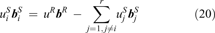
where
While k ≥ r, any r column vectors corresponding to faulty thrusters can be gradually exchanged into an SmaxLIV based on the above process. However, no r thrusters would get into faulty simultaneously on the basis of Proposition 1. If faults occur on thrusters one by one in a period of time, the following FI methodology will not wait to work after r thrusters in a redundant relation have got out of order. Thus, the case of k ≥ r is not an issue in current research.
The proof is completed.
To reach the final goal of FI, choose

Toward the ith of all fixed thrusters, its output effort is

where the superscript s is used to mark parameters of the fixed thruster;

for that desired thrust output

Toward the jth of all vector thrusters, its output effort is

where the definitions of these parameters are similar to the fixed one’s and are omitted. Because vector
Remark 2
The usage of eliminating desired inputs from control input equations for fixed thrusters is to reduce the unnecessary effects. However, the desired inputs of vector thrusters cannot be eliminated because of the nonlinearity.
Suppose there are ms fixed and mv vector thrusters. Based on the above simplifying derivations, equation (21) is reformed as

which is not solvable if some thrusters are redundant for that r < m indicates that the equations for the unknowns are lacking.
Suppose there are mI individual column vectors and mL independent sets of local redundant relations. Define ri as the column vector number of the local SmaxLIV from the ith local redundant relation.
With Theorem 2, the vectors corresponding to all faulty thrusters in a local redundant relation could be contained by a local SmaxLIV. While constructing equation (26), if all the thrusters corresponding to the vectors from one local SmaxLIV of each independent local redundant relation, together with the individual vectors, are kept and the other fault-free (assumed) ones are eliminated, the following group of equations will be got with r unknown parameters.

where
For some thruster combinations in equation (27), all the faulty thrusters or the redundancies of some faulty ones are contained. Thus, with the help of trigonometric functions (
Remark 3
The terms of fault-free (assumed) thrusters are eliminated from equation (26) to produce equation (27) for the reason that the corresponding terms on both sides of the equal sign are always equivalent based on analyzing equations (24) and (25).
Against the above issue, a further simplification process is necessary. As Proposition 1 says, not all thrusters corresponding to an SmaxLIV will get into faulty simultaneously. Thus, combining any
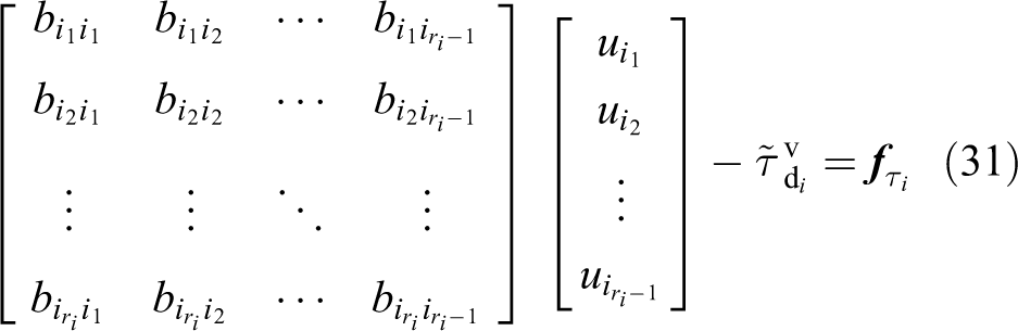
Picking all individual vectors and any ri − 1 column vectors from a local SmaxLIV of each (ith) redundant relation could constitute a matrix

Define an unknown vector u† corresponding to the column vectors of B†, where the element (us) corresponding to a fixed thruster indicates the additive thrust fault (
Reconsidering about constructing equation (27) with only the aforementioned

where B†,
On the basis of the preceding preparation, the following FI methodology could finally be produced.
Theorem 3
For each B† with the corresponding equation (29), if the consistency check is not conflicting, and the number of solved nonzero additive fault parameters (
Proof
It is apparent that
Suppose the equations corresponding to a local SmaxLIV of the ith group in equation (27) has been found as

where
While generating equation (29), one of the ri thrusters is supposed to be fault-free. Without loss of generality, suppose that thruster
where
Define

and

If there is no vector thruster in the ith group, then,

and
where
Toward the case that some vector thrusters are included in the chosen ith group, equation (34) is not suitable because there might be unknown angle faults in Bi. For this problem, using equation (31) together with correlated trigonometric functions (
Against each group of ri − 1 vectors, the aforementioned strategies are suitable. In addition, the issues for individual vectors are simple where the equation that contains any individual vector in equation (29) can be directly solved since it has no correlation with other unknowns. The deduced result directly shows the fault degree of the corresponding individual thruster.
Because some raw redundant relations were merged to be local ones in Algorithm 2, there might be small redundant relations which are parts of some local SmaxLIV. For this case, if all the redundancies of a thruster are included by some chosen ri − 1 thrusters, the deduced result based on the above process will not violate the consistency check; however it could confuse the judgement of faulty thrusters. To solve this problem, a simple way is comparing the number of abruptly emerged faulty thrusters among which the least group contains the right answer. The explanation is referred to Proposition 1.
The proof is completed.
Remark 4
The core of the above methodology is to destroy the redundancy of each thruster, thus the deduced results will exclusively contain all the faults.
Remark 5
Define an error variable as the difference of the terms on both sides of the equal sign of equation (35). If the error variable always tends to zero, the corresponding consistency check succeeds.
Remark 6
This article focuses on solving FI issue for the frame-structure UUVs. The algorithms and theorems are derived for most of the cases however the ones excluded in the assumptions. Thus, the robustness has been partly included in the theoretical derivations and proofs.
Remark 7
Since there are equations to be solved during the FI process, the computational issue is necessary to be claimed. Before solving equation (29), the consistency is firstly checked through observing those error variables. For the ith redundant relation, define the total number of thrusters to be Ti. Thus, the computational times of consistency check are

That is, the total times of selecting ri − 1 thrusters from Ti ones among each redundant relation, because each selection corresponds to an error variable. So the total computational times are

where the later ri − 1 and mI indicate that ri − 1 and mI equations should be solved for each redundant relation and all individual thrusters, respectively.
Based on the aforementioned methodologies, the faulty thrusters of frame-structure UUVs can be isolated, even if there are redundancies. The following section will illustrate the effectiveness of the methodologies with a simulation.
Simulation
This section displays a numerical example. The thrusters of the frame-structure UUV are deployed as shown in Figure 2, where four fixed thrusters (sT1, sT2, sT3, and sT4) are mounted in the same

Thruster deployments of the frame-structure UUV. UUV: unmanned underwater vehicle.
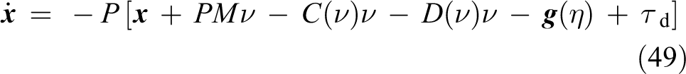
The UUV dynamics model is displayed as 16


where ν and η are vectors of velocities and position/Euler angles, respectively; τ is a vector of model control input; the matrices M, C(ν), and D(ν) denote inertia, Coriolis, and damping, respectively;
The thrust outputs of thrusters


The rank of B is easily calculated as r = 5. Since

Then, all B† could be generated, for example, one B† corresponding to SmaxLIV1 is
To clearly illustrate current work, strange faults are set up for some of these thrusters. The fault set up for sT1 is

where t denotes the time instant from the beginning of the simulation, similarly hereinafter. The fault for sT2 is

and for vT6 is

While the angle fault for vT6 is

The designed faults are obviously unknown to the UUV system. Through equation (1), these faults produce an unknown vector
Lemma 2
If the fault contained in τ from the formula (38) is expressed as

then

where the vector
of which P is a positive definite diagonal matrix; and ν and η are measured states.
Using Lemma 2,
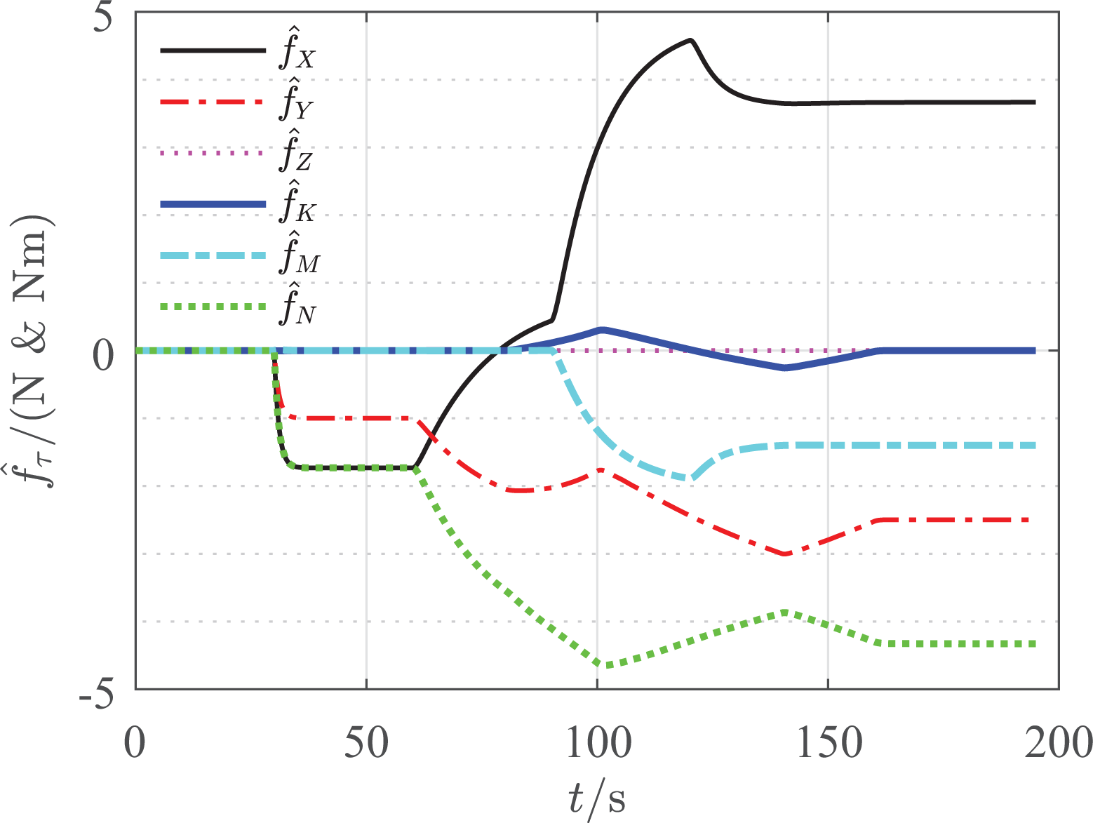
The estimated additive forces and moments in τ.
Theorem 3 is now ready for FI. There is one redundant equation for each B†. Thus,

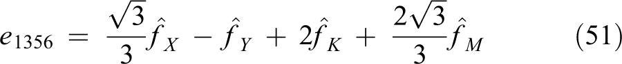


where e1256 is for
Figure 4 gives the consistency check errors throughout this simulation, where the red solid line corresponding to e1256 always tends to 0. However, the green, magenta, and cyan dash-dot lines begin to leave apart from 0 at time instant 30 s because thruster sT1 gets into faulty; the black and blue ones begin to change at time instant 60 s because thruster sT2 gets faulty. These calculating results coincide with the given faults, that is, only the B† which contains all the vectors that correspond to the faulty thrusters can pass the consistency check. While thruster vT6 gets into faulty, there is no change in Figure 4, because it is an individual thruster that has been contained by all B† and the faults are derived directly.

The consistency check errors.
The calculated additive thrust and angle faults are shown in Figures 5 to 8. In these figures, the black dash-dot lines and the red solid lines represent the given and the calculated faults, respectively.
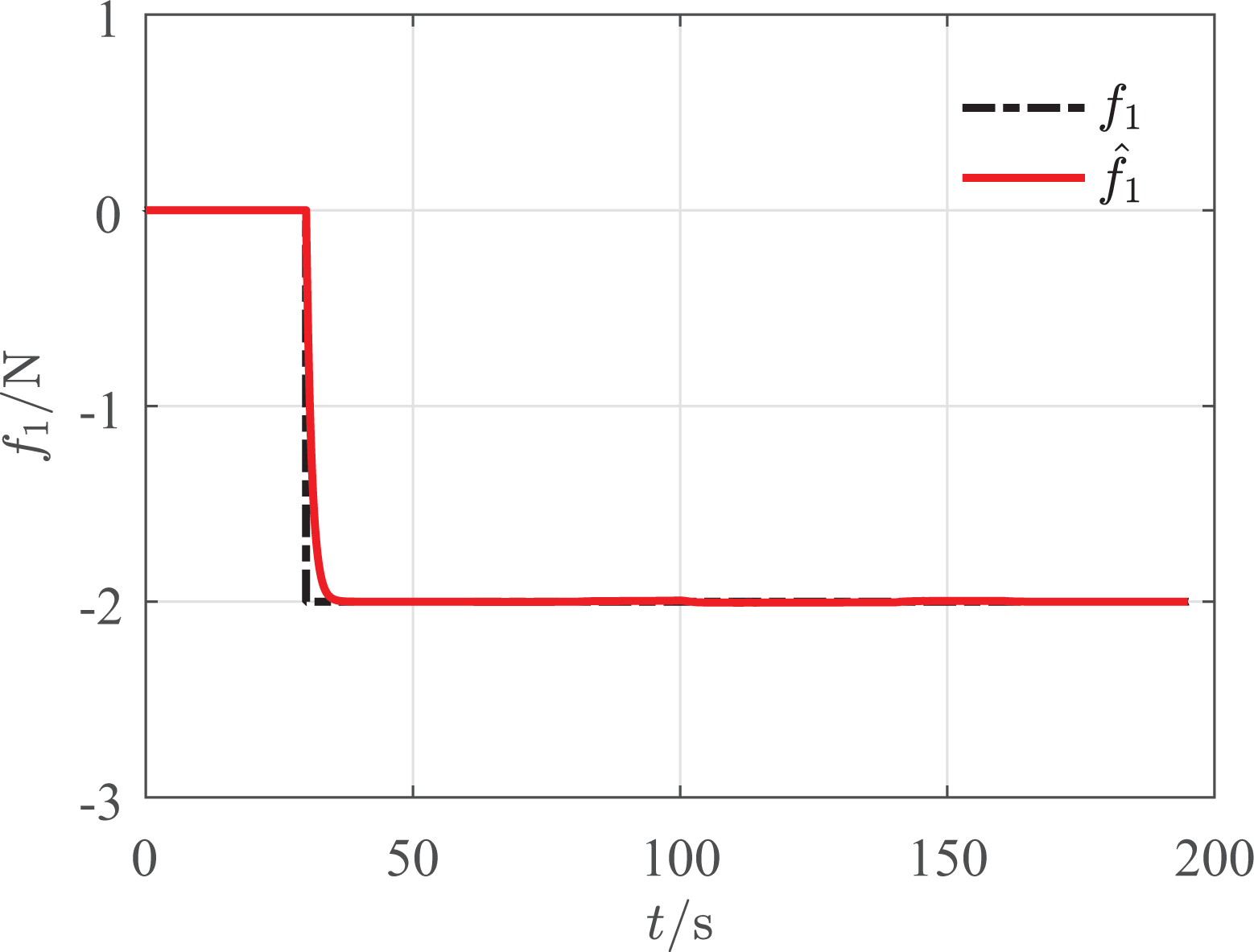
The additive thrust fault of sT1.

The additive thrust fault of sT2.

The additive thrust fault of vT6.
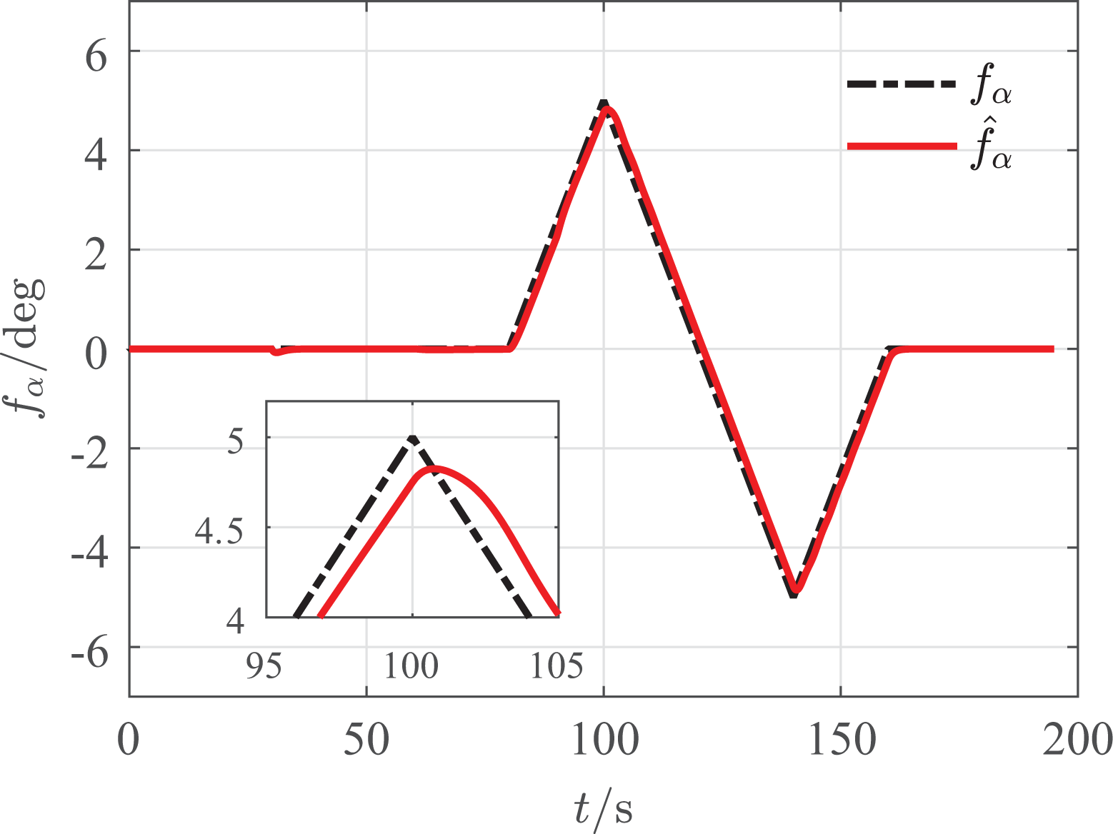
The additive angle fault of vT6.
The overlaps of these lines illustrate the effectiveness of the aforementioned methodologies. While proper thresholds are defined for all thrusters, the red line that departs from 0 and reaches the threshold line indicates fault of the corresponding thruster.
Conclusion
The FI issue for the frame-structure UUVs mounted with redundant thrusters has been revealed in this article, which was carried out against the control input equation where the faults were expressed as additive terms. SmaxLIV of the control matrix were generated by an existing algorithm which led to the first theorem for analyzing the redundant relations among thrusters. The second algorithm brought forward the local SmaxLIV and the individual vectors. With some assumptions, the second theorem was built for restricting the faulty thrusters to local SmaxLIV and individual thrusters. Then, the final theorem was generated to realize the FI, of which the core was to solve a reformed control input equation by taking into the local SmaxLIV and the individual vectors. The faulty thrusters were isolated while the consistency check was passed with right B†.
Future research efforts will be devoted to isolate the faults with faulty thrust directions, and analyze the disturbance robustness for the FI methodology.
Footnotes
Declaration of conflicting interests
The author(s) declared no potential conflicts of interest with respect to the research, authorship, and/or publication of this article.
Funding
The author(s) disclosed receipt of the following financial support for the research, authorship, and/or publication of this article: This work is supported in part by the National Natural Science Foundation of China (Grant 51709023, 51375507, 51405046) and the Fundamental Research Funds for the Central Universities (No. 106112017CDJXY110003).