
Abstract
Welding flaw detection is a key step in manufacturing many components. In offshore chains, every link is manufactured from a steel bar that is bent and the ends joined by flash butt welding. Ultrasonic inspection of the welded area is required for classification. Defects, if any, are parallel to the welded area, which do not favour detection by manual inspection with 45° beams, as per usual practice . This article reports on CIRUS, a robot developed for automatic inspection of the weld area using a combination of pulse-echo and pitch-catch ultrasonic testing. The robot kinematic structure includes global positioning, local positioning and inspection subsystems, and each subsystem design is described in detail. A data acquisition system processes ultrasonic inspection results and provides visual information for the inspector as well as traceability for quality manufacturing.
Introduction
Mooring chains for offshore platforms and ships in the oil and gas industry are highly loaded and subjected to fatigue in a corrosive environment. Therefore, links are subjected to strict certification tests, one being ultrasonic inspection of the weld for every link of the chain.
Certification of mooring chain components is required, with American Bureau of Shipping 1 and Det Norske Veritas 2 considered the main references. The certification procedure includes recommended material, design, manufacture and testing requirements for offshore mooring chain and accessories.
Chains are manufactured in a continuous process by flash butt welding (FBW) and heat treated in a continuous furnace. The welded stud may be accepted for different grades (e.g. NV R3 or R3S), and the required tests and inspections for the finished chain are specified in the certification guide. These consist mainly of proof load tests, break load tests and different mechanical tests after final heat treatment.
Ultrasonic testing (UT) is usually performed manually by technicians who inspect the welding area of the chain using non-destructive technique combining two movements. The inspection is done by axially moving the sensor at a distance proportional to the diameter of the link to be checked. Then a circumferential rotation is made to locate the sensor about another diameter to be inspected. The process continues until the entire chain cross section has been covered. The main drawback is that the inspections are manual, and the data obtained cannot be associated with an exact focus point. Hence, the inspection quality, accuracy and repeatability depend heavily on the technician’s experience and ability.
Several automatic or semi-automatic systems for non-destructive testing (NDT) have been proposed, based on ultrasonic, magnetic particle, liquid penetrant, radiographic, remote visual inspection (RVI), eddy current and low coherence interferometry. 3 –7 Semi-automatic inspection systems have been developed for UT to overcome various manual inspection shortcomings and limitations. Generally, these systems comprise a mobile terminal supporting the UT sensors and a fixed frame. One such example is the BOEING ultrasonic scanning system Maus V, 8 which has the limitation that it is not adaptable to cylindrical geometries.
The In-Line ERW Tube Inspection system developed by Olympus allows inspection of small diameter tubes joined using electric resistance welding. The system is based on a small rolling crane bridge carrying a module for inspection, automatic calibration or maintenance. A mobile robot has also been proposed for in-pipe inspection, 9 and there are several commercial solutions, such as the USM Vision system for the ultrasonic inspection of welds developed by GE Inspection Technology Division.
The automated ultrasonic scanning system focuses on general-purpose automatic inspection systems and consists of an anthropomorphic robot arm and hand carrying ultrasonic sensors. Other automatic inspection devices include linear ultrasound transducers for inspection of linear welds or surface defects in pipes, as described in US patents, such as US-7430913-B2, US-7263889-B2, US-7444876-B2, US-3810384-A, US-4474064-A, US-4559825 and US-A-7305898-B2.
This article presents an ultrasonic inspection system specifically designed for chain link inspection during manufacturing, which allowed the design to be optimized in terms of actuation and mechanical complexity compared to general-purpose inspection systems. Chain links present significant problems with interference between the links. The chain is assembled when inspected and usually suspended from a vertical crane. No current NDT equipment can supply the movements required for inspection, that is, a combination of axial and circumferential motion. Therefore, a new design was required to approach the chain and introduce UT sensors inside the link to be scanned, while avoiding interference with the upper and lower links. 10
Studless chain manufacturing and ultrasonic inspection
The first step in manufacturing a studless chain is cutting the steel bars to length. This operation is done to a batch of bars with one dimensional control on the batch. The next step is heating the bars using a convection furnace or electric heater. Once the temperature of each bar is adequate, the bar is washed using pressurized water to remove furnace scale. The washed bars are transported to the bender for two bending operations. After the first bend, the current end-link of manufactured chain is inserted in the remaining straight part, and the second bend closes the link, adding it to the chain (Figure 1(a)). The two end faces of the link are then joined by FBW, Figure 1(b), burr is removed, and the link width is controlled.

Studless chain manufacturing at VICINAY premises.
Every weld must be inspected to detect defects that could initiate fatigue failure and may be performed with different ultrasonic modes (shear, longitudinal and so on.) and transducer positions. The current method comprises manual ultrasonic examination using the pulse-echo technique. A single transducer search unit is used following ASTM E587, 11 employing angle beam shear waves at 45º and 2.25 MHz. The transducer is located on the surface with its normal on a diameter of the cylinder (see Figure 2). The wave beam is generated at an angle to the diameter and on the plane of the orientation of the transducer, that is, the diameter plane. The wave beam will travel on this plane and the 45° angle allows an easy rule of thumb to deduce the flaw location. If a reflection is detected in the transducer, the defect will be on the intersection of the diameter plane and the transverse welding plane at a distance from the surface equal to the height of the transducer over the welding plane.

Manual examination, pulse-echo inspection technique.
The welding plane in the studless chain passes through the middle of the cylindrical part. The cylindrical surface in the link available to position the inspection probe is limited by the height of two diameters centred on the welding plane, due to each link’s connection with the upper and lower links. Thus, the highest possible position of the transducer during inspection is one diameter above the welding plane. Therefore, the beam angle is restricted to 45° to fully cover the welding plane, even though the standard allows the use of shear waves between 40° and 75° with a single transducer search unit. However, the transducer size does not allow it to be positioned for emission at the correct location in the upper and lower extremes of the inner side of the link. This leads to omitted areas of inspection in the welding plane for smaller chain diameters. Therefore, more reliable and comprehensive inspection techniques are required.
In order to automate the inspection, the functional requirements of the robot were identified, a set of technical specifications were established, including geometric-kinematic and general (global) specifications. The main geometric-kinematic specifications are: motion required for the sensors, ability to inspect the welding plane from above and below, robust inspection system to accommodate diameter uncertainties of 10% in the welding area, adaptability for different link diameters, adjustability for variable welding plane patterns, versatility to inspect more than one production line and minimum required inspection speed: 2 min/link.
The main general specifications are ergonomics (reduce technician’s physical effort), handling safety, calibration using a reference block, low cost, high reliability, easy and low-cost maintenance and operational robustness.
The geometric-kinematic specifications define the robot’s structural design. The main requirement is the motion required for the sensors. In this article, we propose a new inspection strategy combining pulse-echo and pitch-catch techniques considering link geometry and interferences. Traditional pulse-echo inspection with a 45° beam angle will be changed to a combination of pulse-echo and pitch-catch techniques with angle beam longitudinal waves at 30° and 5 MHz. The pulse-echo technique would be more effective on the welding area closer to the surface (outer annulus), that is, with the transducer located close to the welding plane. On the other hand, the pitch-catch technique can completely cover the welding area, although it would be more reliable for locations in the central area of the welding plane. The pitch-catch technique uses two transducers, each on either side of the cylinder, in transmission-reception mode (see Figure 3). If the emitted wave beam encounters a horizontal defect, it reflects towards where the receiver must be placed, and the defect location can be deduced from the trigonometry.
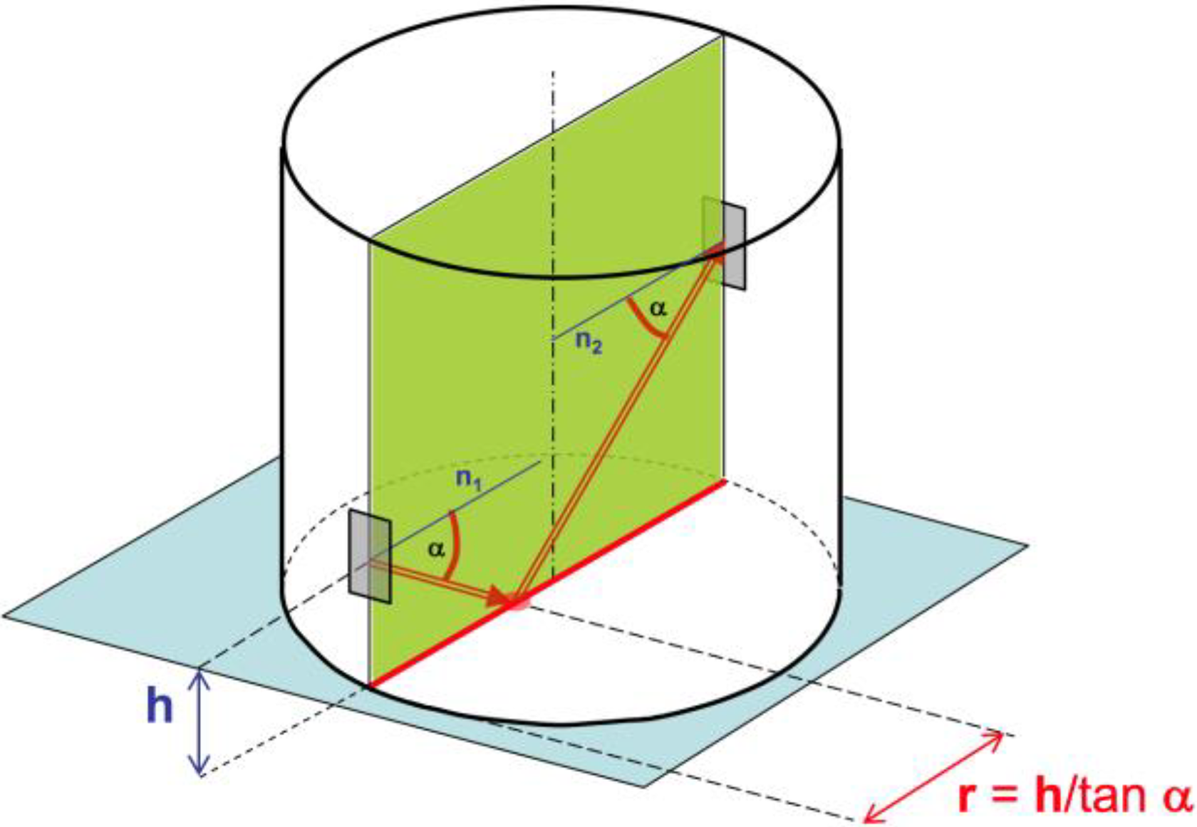
Pitch-catch inspection technique, α = 30°.
Figure 4 shows the proposed inspection strategy combining both the techniques. The left transducer is used as emitter and receiver simultaneously. With 30° beam waves, the accessible surface needed on the link to fully cover the welding plane is a cylinder,

Proposed combination of pulse-echo and pitch-catch techniques.
The proposed technique requires a 30° beam angle, hence longitudinal waves have much higher amplitude than coexisting shear waves (at 15°) and are recommended by ASTM E587 when using 1–40°. The smaller angle also means that the distance travelled by the wave is shorter than 45°; and since the longitudinal waves travel faster than the shear waves, inspection time can be reduced. Although longitudinal waves produce shear waves at reflections, but the shear wave produced by reflection from a flaw parallel to the welding plane will be at 28° from the cylinder’s axis, whereas the longitudinal wave is at 60°, avoiding confusion on reception.
CIRUS robot positioning subsystems
A new robot, called CIRUS, was designed for a precise positioning of the sensors on the chain link and to implement the proposed inspection strategy. The concept was a system manually guided by the user until it is fixed to the link, whereupon it operates automatically to complete the welding plane inspection. Thus, CIRUS can be divided into three different subsystems: global positioning subsystem to assist the user when approaching the link, local positioning subsystem to rigidly clamp the robot on the link and inspection subsystem to synchronize transducer motion for inspection.
The other auxiliary systems, such as the control system, wiring and connectors and water and compressed air circuits, are not described in the current article.
Global positioning subsystem
The global positioning subsystem assists CIRUS to move between production lines (Figure 5) and damps sudden motions in the chain line. Therefore, CIRUS is suspended with a crane from a carrier system. This allows CIRUS to move independently in all three spatial directions.

CIRUS robot subsystems.
Vertical motion (along the chain line) adjusts the position of the robot with respect to the link to be inspected. This motion is achieved by zero-gravity commercial system controlled by two handles in the CIRUS central body. Lateral motion allows CIRUS to move between production lines, facilitating inspection of two production lines with the same equipment. This motion is achieved using a rail fixed to the top of the inspection area. The third motion is CIRUS’ approach to the link, which is also achieved using the rail. Combination of the three motions allows placing CIRUS in a maintenance area without interfering with production.
Local positioning subsystem
The local positioning subsystem adjusts to the link diameter, aligns CIRUS to the welding plane, centres the inspection system with respect to the axis of the cylindrical part of the link and provides a frame for the inspection subsystem.
Several conceptual alternatives were considered during the design process of this subsystem, but we have detailed only the selected solution for the sake of brevity. Once CIRUS is approximately positioned on the cylindrical part of the link, the local positioning system comes into action. The system includes two pneumatic grippers with adjustable axial positions (Figure 6(a)) to clamp CIRUS to the link. These grippers have fingers designed to grasp the cylinder, ensuring the axis is coincident with CIRUS axis (Figure 6(b)).

Pneumatic grippers for the local positioning subsystem.
An adjustable mechanical block is the first component to contact the link and ensure the appropriate distance from the axis for centring while CIRUS approaches the link (Figure 7(a)). A laser level assists the user to position CIRUS vertically on the welding plane. Once in position, pneumatics closes the grippers, firmly clamping CIRUS to the link. Gripper pressure has been optimized to rigidly fix CIRUS to the cylindrical part of the link without sliding, and the fingers simultaneously self-centre the inspection subsystem axis with the link’s circular section axis (Figure 7(b)). Consequently, CIRUS axis is positioned on the cylinder axis, and the system can access a cylindrical surface on the link centred on the welding plane and free of obstacles. Gripper heights can be adjusted for different chain dimensions, and the mechanical blocks are adjusted axially.

Block first contact and gripper self-centring.
CIRUS robot inspection subsystem.
As discussed in “CIRUS robot positioning subsystems” section, the proposed inspection strategy requires synchronized axial motion between the ultrasonic transducers (Figure 4). The required axial (vertical) displacement h = 0.577 × link diameter (for a = 30°). Two additional transducers are located symmetrical to the welding plane to provide redundancy. The additional transducers must have opposite beam directions and move fully synchronously with their pair to avoid false-positive tests. Therefore, each pair of sensors are mounted on a plate, as shown in Figure 8. Plate vertical motion is achieved using a planar linkage described in “Straight vertical motion linkage” section.

Redundant inspection strategy using two pairs of sensors: straight vertical motion.
Vertical motion of the sensors allows inspection along the diameter of the circular section of the welding plane. To inspect the whole circular section of the welding plane, the sensors sweep a cylindrical surface corresponding to 180° circumferential motion (Figure 9). The inspection of each welding plane diameter is stored in a database, providing an inspection map for each chain links, assuring traceability of each weld. Software for inspection map analysis and storage was developed by INTERLAB S.A and is not described in the current article.

Sweeping the cylindrical surface: circumferential motion.
Figure 10 shows the scheme for circumferential and vertical motions. The sensors approach the surface of the link and circumferential motion commences. The mechanisms allowing these motions combined with the linkage designed for straight vertical motion form the inspection subsystem.

Circumferential motion and sensor approximation.
Figure 11(a) shows the central body that supports the inspection subsystem, as well as the local positioning subsystem. It is a rigid frame containing control handles and fixings for the inspection and local positioning subsystems. The lower part includes a motor, pulley and belt to drive a pinion (Figure 11(b)), which is coupled to the ring gear of the inspection subsystem.

Central body: (a) central body and (b) inspection subsystem driving transmission.
The inspection subsystem contains a double ring (one geared, as discussed above), to provide the required circumferential motion to inspect all the diameters of the welding plane. The ring has 120° front opening to access the link. Inductive sensors are used for homing and end of motion signals. The two linkages for the axial vertical motion of the sensor plate are fixed to this ring (Figure 12).

Radial approximation and circumferential motion systems.
The ultrasonic sensors must be in contact with the link cylindrical surface to commence the inspection process. Since CIRUS must be able to inspect different diameter links, a system for radial approximation of the sensors is required. This system is based on the translation of two supports containing the linkages responsible for vertical motion. Two pneumatic actuators move the supports along a linear guide, as shown in Figure 12.
Straight vertical motion linkage
This section discusses the linkage for straight vertical motion of the sensors (Figure 8). The goal was a linkage whose end-effector translates in a vertical straight path, which was achieved in two steps: Select a linkage with a coupler point tracing a quasi-straight path. Based on this linkage, generate a new one with a translational end-effector maintaining the quasi-straight path.
Velocity analysis was performed for the final linkage to verify the required working time specifications for link inspection. The required velocities are quite low so inertial effects were not considered. Finally, quasi-static analysis was performed for a working cycle, considering resistant loads of linkage elements’ weights and friction caused by the ultrasonic sensor displacement along the link’s irregular surface.
Selecting a linkage meeting particular geometric constraints is called type synthesis. In this case, various linkage encyclopaedias were reviewed 12,13 to identify linkages capable of tracing a quasi-straight path. From many different candidates, mostly based on four-bar linkages, we selected the conchoidal straight-line mechanism (Hoecken linkage) shown in Figure 13 for several reasons. The major reason was the ease of applying the second synthesis step. Other reasons will be highlighted after discussing the kinetostatic analysis.
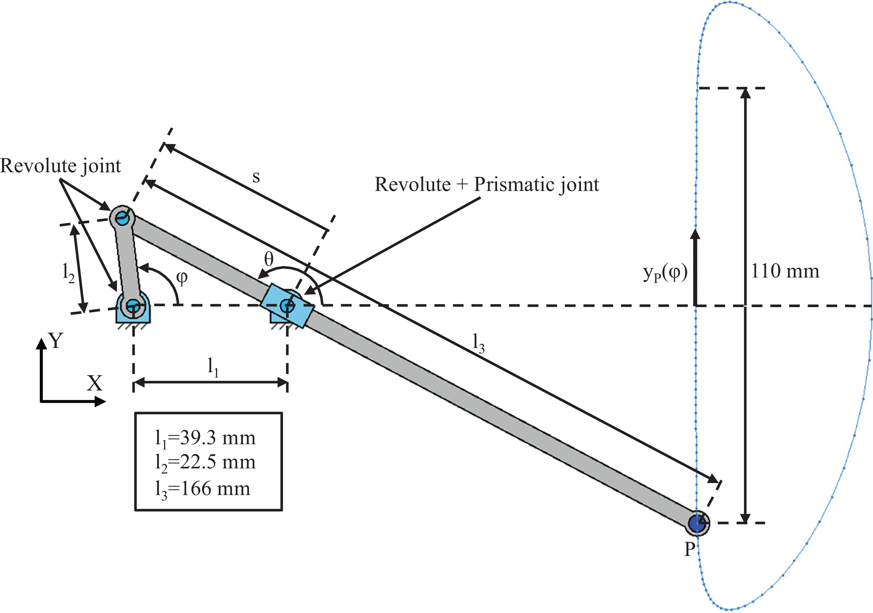
Conchoidal straight-line mechanism.
The conchoidal straight-line mechanism is a one-degree-of-freedom (1-DOF) planar linkage that produces a straight trajectory for its end point, P, over a significant length. Link l2
is connected to the frame and actuated with a rotary motor that controls angle φ. Link l3
slides and rotates on a pin-joint fixed on the same frame. The vertical displacement of P, yP
and its velocity,

and
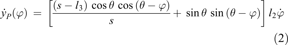
where

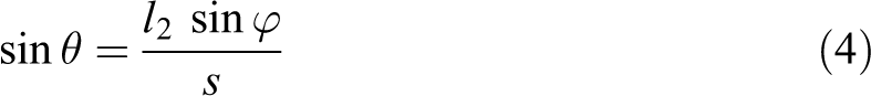

The horizontal displacement of P is negligible along the inspection trajectory.
The Hoecken linkage implemented in CIRUS has the following principal dimensions: l1 = 39.3 mm, l2 = 22.5 mm and l3 = 166 mm. The obtained quasi-straight inspection trajectory has a length of 110 mm, corresponding to a range φ = 97–273°. This inspection trajectory is suitable for chains with diameter up to 190 mm, as shown in Table 1.
Inspection trajectories for the range of chain diameters.

Figure 14 shows the required variation of input angular velocity to achieve constant sensor inspection velocity of 150 mm/s. This quasi-constant angular velocity profile is easily achieved by the actuators, and this relatively constant relationship between input and output velocities is one of the reasons for us to select the Hoecken linkage.

Actuator angular velocity for constant inspection velocity 150 mm/s.
We performed a quasi-static analysis through a complete movement cycle to obtain the required input torque, and reaction forces that appear in the kinematic joints during inspection. As discussed above, inertial forces were considered negligible, and link masses and joint friction were also considered negligible compared to the other masses and effects. The input torque required to balance the vertical force at P of link l3 is

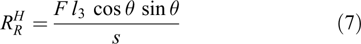

where
Figure 15 shows that the required input torque for the inspection process when F = 50 N is approximately constant through the inspection range 97° ≤ φ ≥ 273°, which was another important reason for the Hoecken linkage choice.
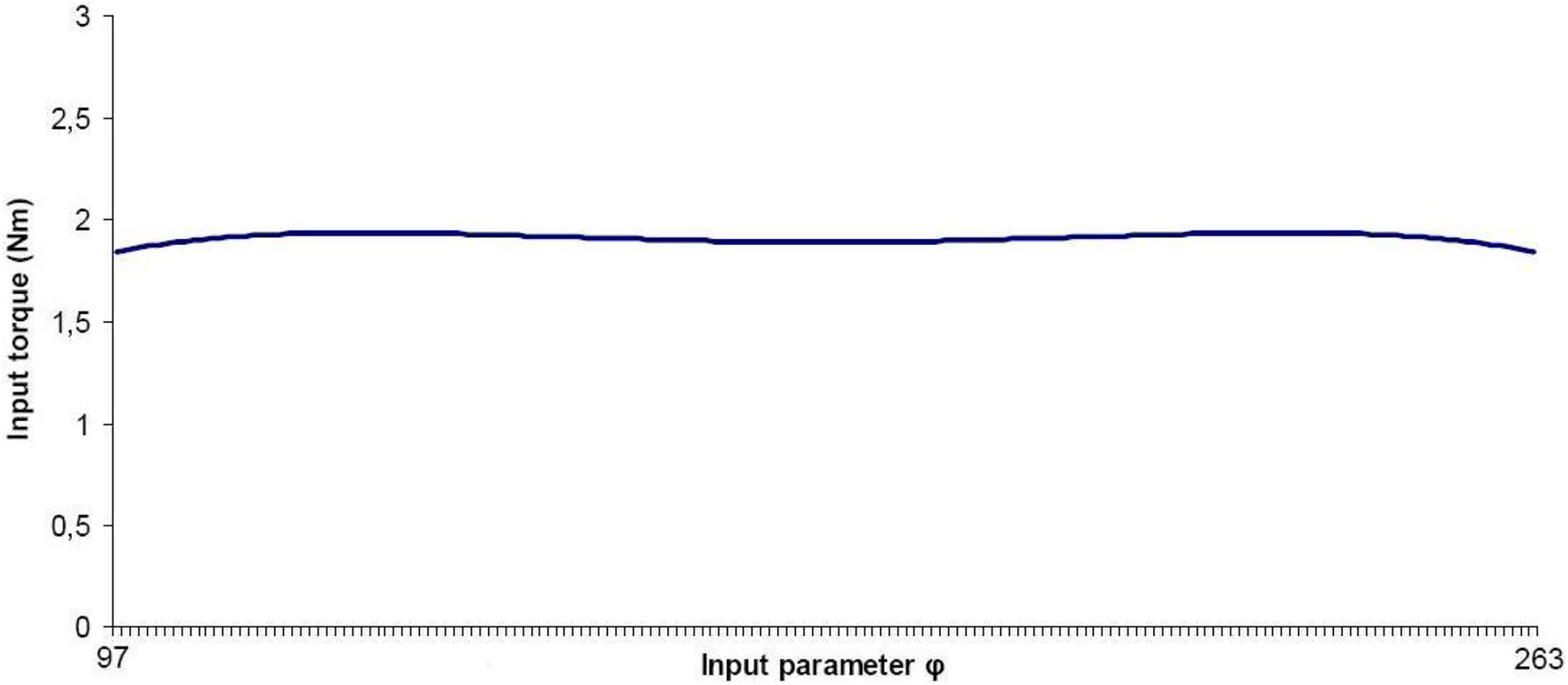
Required input torque through the inspection range.
Finally, we constructed an end-effector with straight translational motion. The end-effector is the plate where the sensors are located upon. We employed two Hoecken linkages in tandem to ensure straight vertical guiding of the plate, with the linkage cranks connected by an additional link, defining an articulated parallelogram, as shown in Figure 16(a). Reduction gearboxes were coupled to each motor to obtain the required input torque, as shown in Figure 16(b).

Inspection mechanism.
Sensor floating mechanism
Figure 17 shows the ultrasonic transducers mounted on a plate joining the coupler points of the tandem linkages. Sensor separation can be easily adjusted manually (Figure 17(a)) to accommodate different link diameters. The distance between the sensors must equal the vertical inspection path, that is 0.577 × link diameter, and a linear guide is provided to facilitate this adjustment. Each sensor is installed in a 2-DOF mounting, allowing orthogonal rotation (Figure 17(a)) of the sensors to adapt to link surface roughness. The mounting is also supported by linear springs (not shown in Figure 17(a) but represented in Figure 17(b) to ensure continuous sensor and link contact during inspection even when encountering surface imperfections.
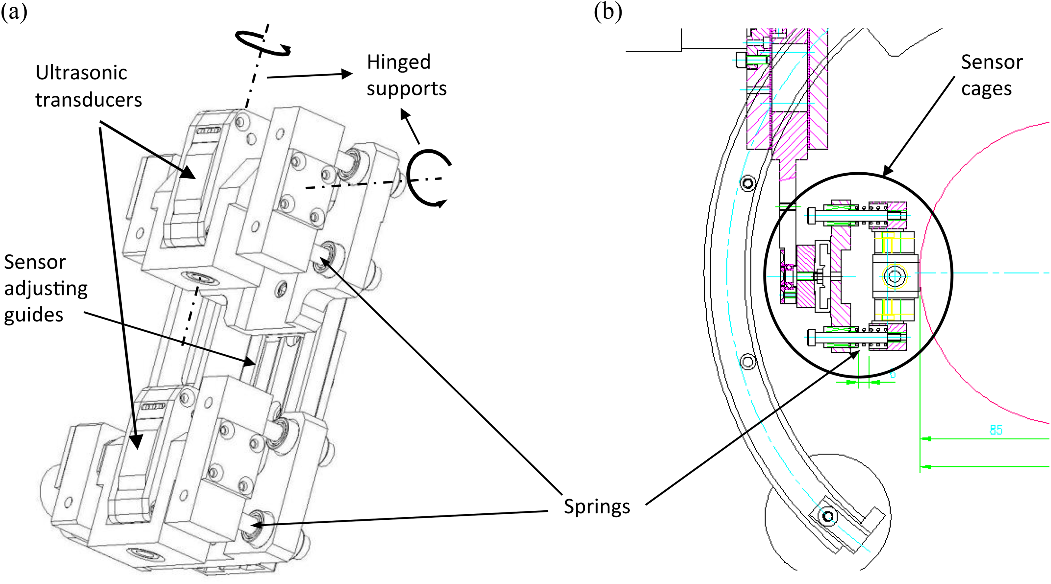
Sensor installation.
Calibration, traceability and final prototype
The ultrasonic inspection system must be calibrated at least once per working shift or 8-h operation, whichever occurs first. 2 Calibration requires an International Institute of Welding type reference constructed from a chain link with similar diameter, surface conditions, chemistry and processing history to the production links to be tested.
The CIRUS system avoids the operator doing repetitive and non-ergonomic tasks. A database stores previous calibration and inspection results for every link, using a colour scale (Figure 9), providing total traceability. The data system records NDT history and processing of each link, materials used, link type and personnel undertaking various operations. Statistical and other analysis are available through the database, providing a powerful tool to assist research and development, and operational maintenance.
Figure 18(a) shows the complete CIRUS mechanical structure; and Figure 18(b) shows the robotic system in operation, fixed to a link and integrated into the production line at VICINAY MARINE S.L.
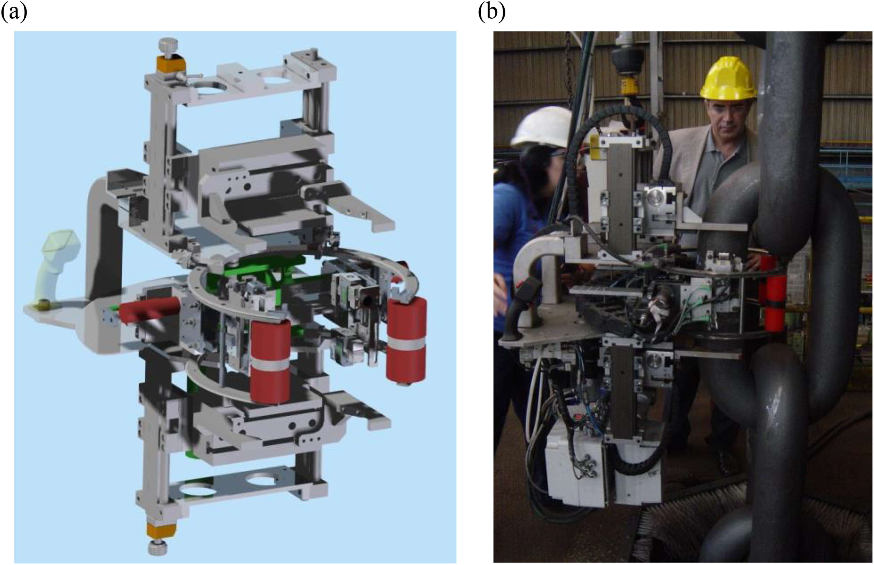
CIRUS robotic ultrasonic chain link inspection system.
Conclusions
This article presented the CIRUS robotic system for ultrasonic inspection of mooring chain link welds. A new inspection strategy combining pulse-echo and pitch-catch techniques was proposed considering link geometry and interferences.
The CIRUS system implements this strategy by fixing rigidly to the inspected link, and the kinematic structure combines synchronized axial and circumferential sensor motion to ensure automatic inspection of every diameter in the welding plane.
CIRUS enormously enhances inspection accuracy and repeatability compared to previous manual systems and also provides complete traceability of the inspection process. An Online Supplementary Video of the CIRUS system performing a chain link inspection cycle is provided at http://www.ehu.eus/compmech/contracts-2/robotics-for-ultrasonic-inspection-of-weldings-in-offshore-chains-cirus/
Supplementary material
Supplemental Material, robot_cirus2 - A robot for non-destructive testing weld inspection of offshore mooring chains
Supplemental Material, robot_cirus2 for A robot for non-destructive testing weld inspection of offshore mooring chains by A Hernandez, O Altuzarra, V Petuya, Ch Pinto, and E Amezua in International Journal of Advanced Robotic Systems
Footnotes
Authors’ note
This project provided a great opportunity for technology transfer between the COMPMECH Research Group of the University of the Basque country UPV/EHU and VICINAY MARINE S.L.
Declaration of conflicting interests
The author(s) declared no potential conflicts of interest with respect to the research, authorship, and/or publication of this article.
Funding
The author(s) disclosed receipt of the following financial support for the research, authorship, and/or publication of this article: This work was supported by VICINAY MARINE S.L, Ministerio de Economía y Competitividad (Project DPI2015-67626-P, MINECO/FEDER, UE), University of the Basque Country (UPV/EHU) (Program UFI 11/29) and Departamento de Educación, Política Lingüística y Cultura of the Regional Government of the Basque Country (Project IT949-16).
Supplementary material
Supplementary material for this article is available online.
References
Supplementary Material
Please find the following supplemental material available below.
For Open Access articles published under a Creative Commons License, all supplemental material carries the same license as the article it is associated with.
For non-Open Access articles published, all supplemental material carries a non-exclusive license, and permission requests for re-use of supplemental material or any part of supplemental material shall be sent directly to the copyright owner as specified in the copyright notice associated with the article.