
Abstract
Exploration robots face a challenge in maintaining stability when traversing uneven surfaces. This article aims to address this issue by proposing the design of a drive system that enables an exploration robot to adapt to terrain irregularities and achieve greater traction capability. The design parameters for the robot’s desired operation are established. Subsequently, the design of the drive system is proposed, consisting of three subsystems: the suspension system, the traction system, and the transmission system. To ensure that the proposed design functions properly under the desired parameters, an analysis is conducted using finite element methods. The resulting analysis provides the stresses, deformations, and safety factors of the components that make up the drive system. Overall, the analyzed components exhibit minimal deformations, which remain within the elastic range, as the yield strength of the materials from which they are made is not exceeded. This article concludes that the proposed design operates reliably under the stresses it must withstand and that a drive system capable of adapting to surface irregularities is essential, as it enhances the mobility of exploration robots.
Introduction
In recent years, the development of robots focused on exploration has advanced significantly due to the need to investigate environments that are either inaccessible or pose high risks to humans.
Examples of these include underwater robots, agricultural robots, planetary explorers, surveillance, security robots, reconnaissance robots, and those deployed in the event of terrorist attacks or radioactive or chemical contamination.1,2 Among these is the Spot robot from Boston Dynamics, a quadruped robot designed to operate in various environments, 3 as well as the Husky robot from Clearpath Robotics, an all-terrain robot intended for outdoor research purposes. 4
This growing interest in exploring challenging environments has been driven by the need to better understand our planet, as well as the increasing concern for human safety in emergency situations. 5
In the design of robots intended for the exploration of challenging and hard-to-reach terrains, a primary challenge arises: ensuring the robot’s stability as well as its ability to operate effectively on uneven terrain. Mobility on challenging surfaces, such as rugged terrain, presents a significant challenge to the efficiency of exploration robots. 6
Thus, the drive system of exploration robots becomes a crucial factor in determining their efficiency during navigation in difficult environments.
Among the subsystems that stand out within the drive system is the power transmission system. This system allows the transmission of mechanical energy from the motor to the working components, with transformations of speed, force, or torque. 7
Among the most common transmission systems are friction wheel transmission, belt transmission, which is detailed in Flores, 7 gear transmission, described in Quiroga et al., 8 and chain transmission.
In this last type of transmission, the driving sprocket is responsible for receiving the main motion to be transmitted, causing the chain to move and drive the driven sprocket. 7 In this case, the transmission ratio is determined by the number of teeth on the sprockets that connect the chain. 9 The most commonly used type of chain is the roller chain, in which each roller, when rotating over the pins, significantly reduces the friction between the chain and the toothed wheels. 10
On the other hand, suspension systems are also a vital part of the drive system. They isolate the structure or chassis from terrain irregularities, reducing the force transmitted to the chassis. Additionally, they ensure contact between the terrain and the tire or track, with the aim of maintaining steering maneuverability and preventing damage to the vehicle. 11
Suspension systems are classified into three types based on the control they exert over their parameters. The active type uses actuators, as explained in Ezeta et al. 11 The semi-active type uses dampers that can change their damping coefficient, as shown in Ezeta et al. 11 In contrast, the passive type stores energy through springs and dissipates it via dampers. The parameters of this type of suspension system are constant and are directly related to the mechanical characteristics of the spring and damper. 11 The spring is designed to support the static load and allow movement around the stationary position.12,13
It is necessary to conduct a mechanical analysis of the components of the drive system to verify their proper functioning. However, due to their geometric complexity, obtaining precise solutions is challenging. In these cases, the finite element method is used. This is a numerical technique that provides an approximate solution, which can be highly accurate for problems that lack closed-form solutions.14,15
However, it is essential to ensure the convergence of the finite element method. The analysis is said to converge if, as the element size decreases, the obtained solution approaches the exact solution.16,17 Meshing in finite element analysis is crucial for the simulation of numerical analysis, as it directly affects the accuracy of the numerical calculation results. 18
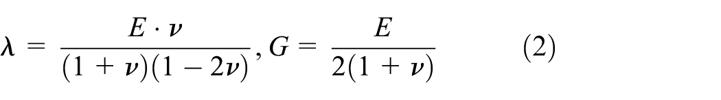
The fundamental constitutive law used in linear elastic materials is known as Hooke’s Law. This law is represented by equation (1), which relates stresses to deformation.14,16 In this equation,

In a practical case of finite element analysis, there are known variables that are related to the material properties (Young’s modulus, Poisson’s ratio, and density), geometry (dimensions and shape), and boundary conditions (displacements such as fixed supports or preset movements, and forces such as applied loads). 14
In finite element analysis, the unknown variables include nodal displacements
Equation (3) shows the stress-deformation relationship previously presented in equation (1), but in matrix form:

The unknowns (displacements, deformations, and stresses) can be determined by inputting the known material properties as well as the boundary conditions into the finite element analysis software. In cases where the geometry is complex and finite element analysis cannot be performed with the required precision, the nested submodeling technique is applied. This technique allows for refining the mesh requirements. 19
This article aims to address the issue of stability and mobility in exploration robots through a drive system capable of adapting to terrain irregularities. The proposed drive system is presented, which must be capable of adapting to terrain surfaces and improving grip on those surfaces. It features a chain-based transmission system and a continuous track traction system. Additionally, a passive suspension system is applied to enhance the robot’s stability on rugged terrain. It is important to mention that the analysis of the drive system components is carried out using the finite element method. Upon verifying the components of the drive system, it is found that the system can withstand the expected loads without any issues, and that its suspension system can adapt to different surfaces. The adaptation of the drive system to surface irregularities, as well as the improvement in traction in this exploration robot, makes this work significant as it addresses the lack of stability and poor mobility of non-aerial exploration robots.
Materials and methods
Design parameters of the drive system
The drive system must be capable of navigating over various types of terrain, such as sandy terrain, gravel-covered surfaces, cemented surfaces, and cobblestone areas, among others. In Jia et al., 20 it is shown that sand has a high rolling resistance coefficient compared to other surfaces such as cement. Based on this research, it is determined that the robot must be capable of navigating terrains with a rolling resistance coefficient higher than that of sand. Consequently, a rolling resistance coefficient of up to 0.08 is established.
As an exploration robot, the system must be sufficiently robust to support not only its own weight but also the weight of onboard devices and any additional modules it may carry during operation. The baseline configuration includes the following components: a 22.2 V 6000 mAh LiPo battery, an NVIDIA Jetson Nano Developer Kit, an Arduino Mega with its corresponding shield, a transmission system consisting of both double and single chains, aluminum shafts and sprockets, structural aluminum profiles with their respective mounts, shock absorbers, suspension system links and wheels, fastening elements such as bolts and nuts, and a housing manufactured through additive processes. The total estimated weight of all these components is ∼65 kg.
It is crucial to consider that the design of the drive system should allow for future upgrades to enhance the robot’s autonomy. This implies that it must be capable of adapting to an increase in weight due to the incorporation of larger batteries, as well as the addition of modules and boards for various types of tasks or activities. Consequently, it is determined that the drive system must have the capacity to handle a total load of ∼70 kg.
The exploration robot must be capable of moving at a maximum speed equivalent to the average walking speed of an adult human. Based on the studies in Lakmazaheri et al., 21 a speed of 1 m/s. is defined for the robot’s drive system to ensure that it does not pose any danger to humans or wildlife.
To ensure the robot’s stability on uneven terrain, it is crucial to take into account both its angular and linear acceleration. Variations in these accelerations can compromise the robot’s balance. Therefore, it is necessary to establish optimal acceleration values that guarantee stability without compromising movement efficiency. Consequently, the maximum linear acceleration of the robot is set at 1 m/s2, while the maximum angular acceleration is set at 1 rad/s2.
Design of the drive system
The drive system consists of three subsystems, which are: suspension system, traction system, and power transmission system. For components subjected to significant loads, 6061 T4 aluminum is selected due to its excellent mechanical strength and machinability.22,23 On the other hand, for components with complex geometries that are subjected to loads, the material known as PC Blend is used due to its impact resistance and good resistance to tensile creep. 24 Finally, the material known as TPU is used for components designed to reduce vibrations and absorb potential impacts. 25
Design of the suspension system
he suspension system allows the track to adapt to surface irregularities, enabling the robot to remain stable during navigation. This system features a mechanism that integrates a damping device, which, through its compression and elongation, allows the track to adjust to the terrain (Figure 1).
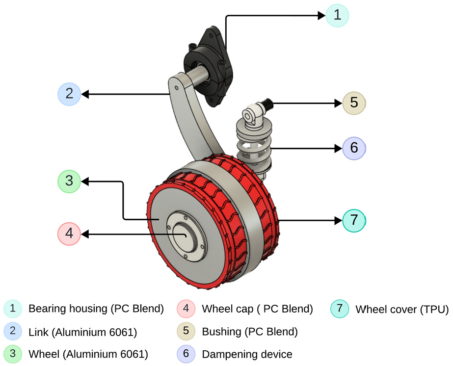
Suspension system.
Design of the traction system
This system allows the robot to achieve better grip with the surface it traverses. A track-based traction system is proposed, utilizing transmission chains. Plates are attached to these chains, which are coated with TPU to enhance surface grip, absorb impacts, and reduce vibrations. The plates are made of ASTM 1200 aluminum due to its considerable mechanical strength and corrosion resistance (Figure 2).26,27

Traction system.
Design of the power transmission system
It is designed to increase the torque of the actuators. Sprockets and chains are used to transmit power from the driving sprocket to the driven sprocket. This type of transmission system ensures that the arrangement and distance between the sprockets are not limiting factors.
For the transmission system and, by extension, the traction system, to function properly, a tensioning mechanism must be included. Maintaining proper chain tension is the tensioning wheel’s main job in order to avoid misalignment or disengagement from the driving and driven sprockets. This prevents premature wear of mechanical components and ensures effective and continuous power transmission. 28 Furthermore, a tensioning system makes precise adjustments possible without requiring intricate disassembly procedures, greatly simplifying both the assembly and maintenance processes (Figure 3).
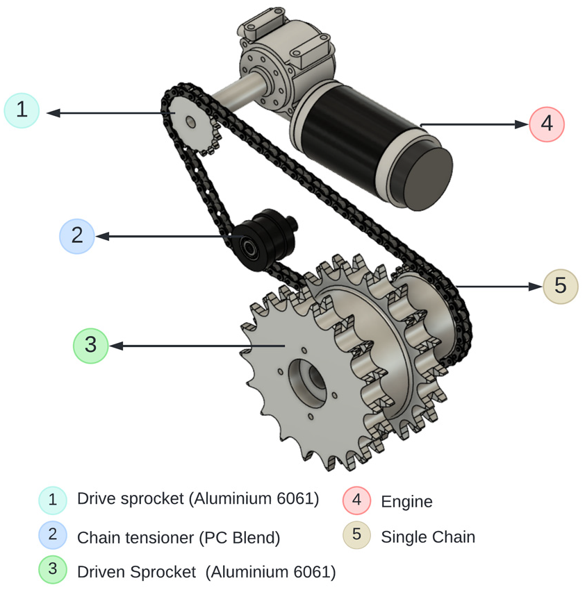
Transmission system.
For motor selection, it is considered that the robot must be capable of initiating motion on both flat and inclined planes. The corresponding free-body diagrams are shown in accordance with this requirement. Notably, consideration is given to the inclination of the surface the robot travels on. As shown in Figure 4, this inclination is represented by the angle


Free body diagram of the robot considering the inclination angle of the surface.
Next, the summation of forces along the X-axis is carried out. In this analysis, the sign functions are used to properly define the direction of the reaction force, while

The torque transmitted by the sprockets is expressed by the following equation:
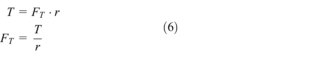
By substituting equation (6) into equation (5) and performing the corresponding development, equation (7) is obtained:

Next, the moment summation is carried out in order to continue the dynamic analysis of the system (Figure 5):


Free body diagram of the robot from the top view.
The system of equations composed of equations (7) and (8) is solved, yielding equations (9) and (10), which allow for the determination of the required torque values in the driving sprockets:


On the basis of the design, the values of the sprocket’s pitch radius as well as the distance between the track and the center of mass are obtained. On the other hand, on the basis of the required operational parameters of the robot, the values for the robot’s mass, the normal force, the robot’s linear and angular acceleration, and the rolling resistance coefficient are determined. The moment of inertia is obtained from the 3D modeling using a CAD software.
It is necessary to analyze the three possible startup scenarios of the robot. The robot can start with a straight-line trajectory, a curved trajectory, or around its own axis. The most demanding case in terms of torque occurs when the robot begins its motion along a curved path on an inclined surface. For this analysis, an inclination angle of 15° is considered. Under these conditions, the maximum torque required at the sprockets driving the tracks reaches
Analysis of the drive system using finite element method
In order to ensure the integrity of the drivetrain system, it is essential to assess its ability to withstand the loads and stresses to which it may be subjected during operation. This analysis considers the critical scenario of a mechanical jamming event within the drivetrain. Figure 6 illustrates the components of the system that would be affected under such conditions.
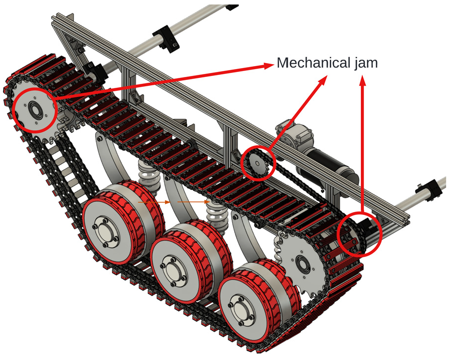
Components affected by a mechanical jam in the drive system.
Given the geometric complexity of the components involved, the finite element method (FEM) is used. This method divides a complex model into smaller finite elements, over which the governing physical equations are solved, allowing for a highly accurate approximation of the behavior of the system.
To perform this analysis, ANSYS 2022 R1 is used. ANSYS enables reliable predictions of stresses, deformations, displacements, and safety factors, contributing to the structural validation of the design prior to manufacturing. Specifically, the Static Structural module of ANSYS is used, which is tailored for stress analysis under static loading conditions. This module allows users to define materials, apply boundary conditions and external loads, and obtain detailed insights into the mechanical behavior of each component. In addition, it enables the visualization of stress and strain distributions throughout the model and the identification of critical regions that are susceptible to failure. 29
Analysis of the drive sprocket
Being connected to the motor shaft, it is subjected to a torsional stress caused by the torque of the motor (

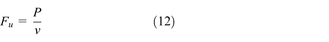
The useful force is represented by equation (12), while the centrifugal force is represented by equation (13):

Both equations utilize the linear velocity of the chain, which can be determined using equation (14):

It is essential to present the technical parameters of the drive sprocket and the single chain, as these are critical to accurately characterizing the mechanical behavior of the system. The relevant data include: the chain or sprocket pitch (

Free body diagram of the drive sprocket.
In addition, the rotational speed of the drive sprocket at the point of maximum motor torque (
Using these parameters, both the useful tensile force and the centrifugal force in the chain can be calculated, allowing the determination of the maximum force exerted by the chain, which is
Figure 8 illustrates the configuration used to represent the critical case of a jamming event in the drive sprocket. In this scenario, it is assumed that there is a total restriction of the rotational motion of the sprocket due to mechanical blockage or malfunction in the driven sprocket. Since both sprockets are mechanically connected via a single chain, any obstruction in the driven sprocket prevents the free rotation of the drive sprocket. To simulate this jamming condition, a fixed support is applied. Under this constraint, the motor attempts to overcome the blockage by delivering its maximum starting torque.

Application of loads on the drive sprocket.
Analysis of the driven sprocket
This sprocket is affected by both the force of the single chain (

Free body diagram of the driven sprocket.
It is fundamental to present the technical specifications of the driven sprocket, as it represents a key component of the robot’s traction and transmission systems. This element consists of three rigidly connected gears: two 18-tooth sprockets that guide the double chains of the track system, and a third 27-tooth sprocket that receives the power transmitted from the drive sprocket. These three sprockets are integrated into a single mechanical component, ensuring uniform, efficient, and synchronized power transmission.
For the 27-tooth sprocket, the critical parameters include the sprocket pitch (
Regarding the 18-tooth sprockets that engage with the double chains of the tracks, their relevant specifications are: sprocket pitch (
Using this information and the equations previously discussed, the maximum force exerted by the double chains can be determined, which yields
Figure 10 illustrates the configuration used to represent the critical case of a jamming event in the driven sprocket. This sprocket is mounted on a shaft via bearings, which under normal conditions allow free rotational movement. However, for the purposes of this analysis, it is assumed that the bearings fail, resulting in a complete restriction of rotation. To simulate this scenario, a fixed support is applied at the contact point where the bearings interface with the sprocket. It is important to note that the fixed support at the central hole is sufficient to ensure that the system remains in equilibrium within the static analysis.

Application of loads on the driven sprocket.
Analysis of the traction system sprocket
The torque affecting this sprocket is the same as the torque of the driven sprocket. On the other hand, the double chain is the only one exerting force on the teeth of the traction system sprocket Figure 11.

Free body diagram of the traction system sprocket.
It is important to present the technical specifications of the sprocket used in the traction system. This sprocket consists of two rigidly connected 18-tooth gears, which support the double chains that form the track mechanism. Both sprockets are integrated into a single mechanical component, ensuring uniform, and synchronized transmission.
The most relevant parameters of these 18-tooth sprockets include the pitch (
Figure 12 presents the configuration used to simulate the critical case of a jamming event in the traction system sprocket. This sprocket is mounted on a shaft via bearings, which are assumed to fail in this analysis, thereby restricting rotational movement. To model this condition, a fixed support is applied at the hole where the bearings are located.

Application of loads on the traction system sprocket.
Regarding the applied load, the chain force is concentrated on a single tooth of the sprocket, as it represents the maximum load that can be transmitted according to static analysis. Although, in practice, multiple teeth share the load, the forces on the remaining teeth are significantly lower and not critical for evaluating the worst-case scenario.
Analysis of the shaft for the sprockets
This shaft is subjected to bending stresses due to the weight of the sprockets, and also to torsional stresses due to the torque from the sprockets. It is important to highlight that the sprocket torque is determined by the power transmission system, meaning that the torque exerted by the sprockets on the shaft is the same torque that reaches the driven sprocket (

Free body diagram of the shaft for the sprockets.
Figure 14 shows the configuration used to analyze how the sprocket shaft is affected under a critical mechanical jamming scenario in the drive system. In this analysis, it is assumed that the bearings that connect the sprockets to the shaft fail, thus preventing free rotation. As a consequence, the torque of the sprockets is transmitted directly to the shaft. In addition, static load due to the weight of the sprockets acting on the shaft is also considered.
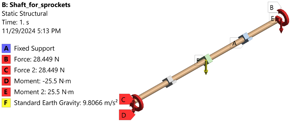
Application of loads on the shaft for the sprockets.
Analysis of the suspension system
This analysis accounts for the uneven distribution of forces on the suspension wheels, which typically occurs when the robot navigates over irregular terrain or encounters obstacles. A static structural analysis was conducted with the objective of evaluating the maximum load that the suspension system can withstand under such conditions. To represent this scenario, a parametric study of the normal force was implemented in ANSYS, applying the force to a single wheel of the suspension system. In order to represent different levels of terrain irregularity, this parametrization consists of a sequence of force values that increase incrementally, simulating progressively higher loads on the wheel. Frictional effects are considered in the simulation setup, although their influence may be limited due to the static nature of the analysis.
Given that the suspension system has six wheels, the initial force value is equivalent to one sixth of the robot’s total weight, which is the ideal normal force that a single wheel should support under uniform conditions. To replicate scenarios in which one wheel carries a disproportionately greater load because of terrain obstacles, the force values are progressively increased from that baseline. By avoiding the need to simulate the entire suspension system, this method optimizes computational resources while allowing the evaluation of the structural behavior under critical conditions. For this analysis, a flexible-type connection is used in order to simulate the damping device. The spring’s elastic constant is input into this connection (Figures 15 and 16).

Free body diagram of the suspension system.

Application of loads on the traction system sprocket.
Results and discussion
For the validation of the analyzed components, the approach of comparing the maximum stress obtained through finite element analysis (FEA) with the yield strength of the material is employed, along with the evaluation of safety factors and maximum deformation. This method makes it possible to assess whether the component can withstand the expected loads without undergoing plastic failure. The validity of this approach has been supported by Khalifa 30 and Sarıtaş et al. 31
Results of the analysis of the drive sprocket
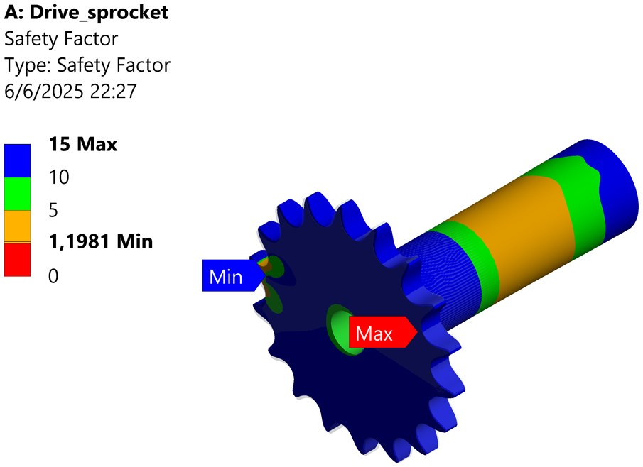
The finite element method analysis shows that the driving sprocket experiences a maximum deformation of 0.015187 mm, while the maximum stress present is 69.058 MPa. Additionally, it is found that the minimum safety factor against stress is 1.897, and the minimum safety factor against fatigue is 1.1981 (Figures 17 –20).

Deformation of the drive sprocket.

Stress on the drive sprocket.

Safety factor against the stress on the drive sprocket.
Safety factor against the fatigue on the drive sprocket.
It is important to emphasize that the material of the driving sprocket has a yield strength of 131 MPa. Given that the maximum stress does not exceed the yield strength, it can be concluded that the driving sprocket remains within the elastic range, and therefore, the deformation is not permanent. Based on this, it is verified that the sprocket is suitable for its intended use. This can also be confirmed by the minimum safety factor of the sprocket, which is >1.
Results of the analysis of the driven sprocket
Through the finite element analysis, it is found that the maximum stress in the sprocket is 56.327 MPa. This sprocket reaches a maximum deformation of 0.0075821 mm. Regarding the minimum safety factors against stress and fatigue, they are 2.3257 and 1.4689, respectively (Figures 21 –24).

Deformation of the driven sprocket.

Stress on the driven sprocket.

Safety factor against the stress on the driven sprocket.

Safety factor against the fatigue on the driven sprocket.
The material from which it is made has a yield strength of 131 MPa. Since the maximum stress does not exceed the material’s yield strength, it can be inferred that the driven sprocket remains within the elastic range, which ensures that the deformation is not permanent. This allows us to deduce that the sprocket is capable of working under the specified loads without any difficulty. The safety factor of this sprocket confirms this, as it is >1.
Results of the analysis of the traction system sprocket
Through the analysis of the total stress in the sprocket, it is found that the maximum stress value present is 9.2414 MPa. Additionally, the maximum deformation is 0.0022191 mm. Finally, it can be observed that the minimum safety factors are 14.175 against stress and 8.9531 against fatigue (Figures 25 –28).

Deformation of the traction system sprocket.

Stress on the traction system sprocket.

Safety factor against the stress on the traction system sprocket.
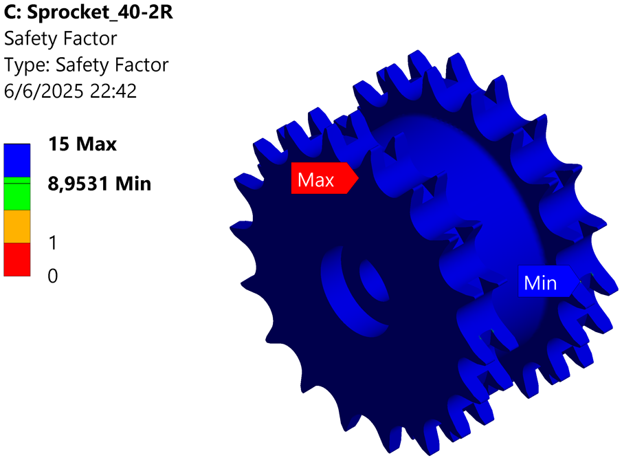
Safety factor against the fatigue on the traction system sprocket.
Since this sprocket is made of a material with a yield strength of 131 MPa, it experiences deformation within the elastic range, indicating that the deformation is not permanent. As a result, it can be verified that the sprocket is capable of performing optimally under the specified conditions. The minimum safety factor further supports this, as it is 14.175.
Results of the shaft analysis for the sprockets
The results obtained from the finite element method analysis for the structural static calculation of the shaft for the sprockets show that the maximum deformation is 0.2988 mm, while the maximum stress in the shaft reaches 35.69 MPa. This stress is present in the shaft, but not in its supports. Finally, it is noted that the minimum safety factor against stress is 3.6705 (Figures 29 –31).

Deformation of the shaft for the sprockets.
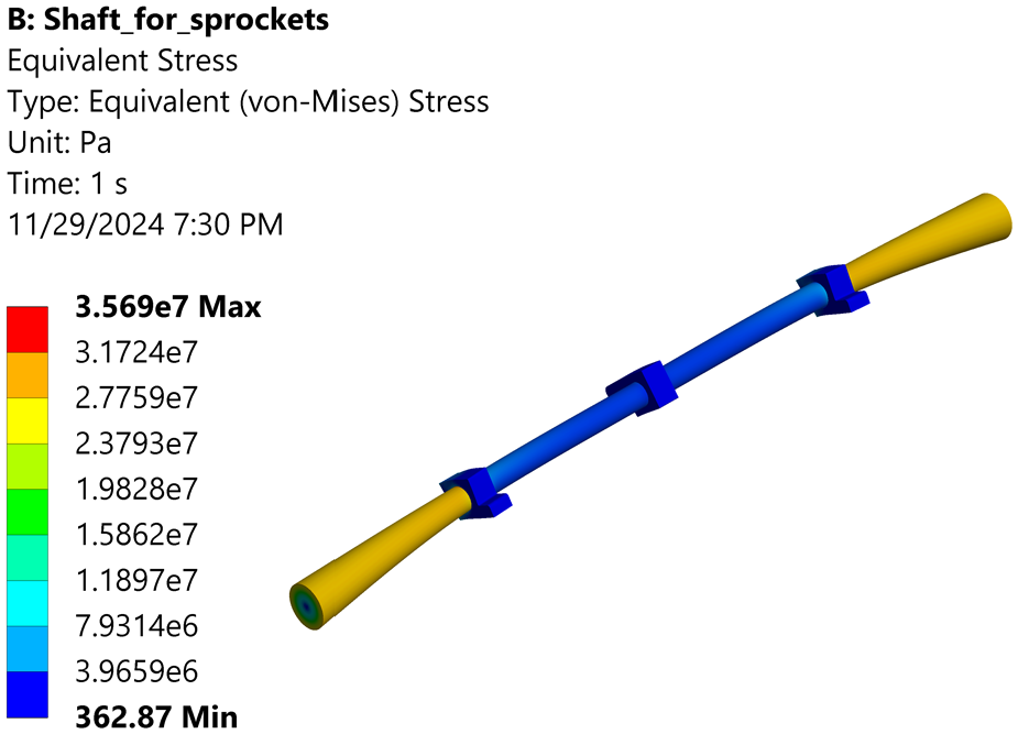
Stress on the shaft for the sprockets.

Safety factor against the stress on the shaft for the sprockets.
It is important to emphasize that the maximum stress is located on the shaft, not in the supports that connect it to the robot’s structure. Upon verifying the material from which it is made, which has a yield strength of 131 MPa, it can be deduced that the shaft will not exceed the elastic range, ensuring that the deformation is not permanent. Thus, it is inferred that the shaft is capable of operating under the intended loads without any issues. The safety factor confirms this, as the minimum safety factor is 3.6705.
Results of the analysis of the suspension system
The results from the static structural analysis of the suspension system indicate that the maximum deformation is 0.2046 mm, while the maximum stress does not exceed 17.928 MPa. Additionally, it can be seen that the minimum safety factor against stress is 7.307 (Figures 32 –34).

Deformation of the suspension system.

Stress on the suspension system.
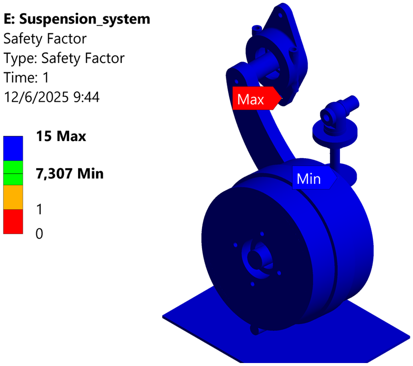
Safety factor against the stress on the suspension system.
The maximum stress that the suspension system experiences occurs in the damping device, which is made of a material with a yield strength of 131 MPa. It can be observed that when a force of 114.5 N is applied, the system reaches a maximum stress of 17.928 MPa. This means that the system remains within the elastic zone, and therefore, the deformation is not permanent. The minimum safety factor is 7.307, indicating that the system can withstand the specified load without any issues.
Additionally, the parameterization of the applied force to the suspension system is performed. This parameterization results in three curves that represent the applied force in relation to the maximum deformation, maximum stress, and minimum safety factor (Figures 35 –37).

Curve of applied force versus maximum deformation.

Curve of applied force versus maximum stress.

Curve of applied force versus safety factor.
With the parametrization, it can be observed that as the applied load increases, the maximum stress also increases, as does the maximum deformation. On the other hand, the minimum safety factor is inversely proportional to the applied load. As presented in Table 1, when the highest load of 204.5 N is applied, the system experiences a maximum total stress of 40.075 MPa, and the maximum deformation is 0.4466 mm. Comparing the yield strength with the maximum stress shows that the system does not exceed the elastic limit. The minimum safety factor of 3.2689 indicates that the system is capable of withstanding a load higher than the specified one.
Results of the parametrization of the applied force.

Conclusions
In exploration robots, a drive system capable of adapting to surface irregularities is of utmost importance as it enhances the mobility of these robots in complex terrains. This has direct applications in various fields such as research, security, infrastructure assessment, search and rescue, among others.
The design was executed and the materials for each system component were selected, considering that they must be sufficiently resistant to stresses as well as to corrosion due to the environment in which they will operate. It is important to emphasize that during the design phase, the necessary considerations were made to facilitate both the manufacturing and assembly of the system.
With the proposed design, an analysis was carried out to verify its functionality. Due to the complex geometries of the drive system, it was necessary to use finite element analysis. It is important to mention that this analysis was conducted on the components that are most relevant in terms of performance and safety.
Through finite element analysis, it is confirmed that the maximum stresses of the analyzed components, which are part of the drive system, do not exceed the yield strength of their respective materials. This is reflected in the safety factors, as well as in the deformations, which are minimal.
Regarding the parametrization of the suspension system, it is observed that as the applied load increases, both the maximum stress and the maximum deformation also increase. On the other hand, the minimum safety factor of the system decreases as the applied load increases. This parametrization allows visualization of how deformations, stresses, and safety factors behave based on the applied force, in addition to demonstrating that the system can withstand loads greater than those established.
It is important to emphasize that the purpose of the proposed drive system is to provide the robot with constant contact with the ground surface, thus enabling the robot to have better climbing capability, overcome obstacles, and maneuver in challenging environments.
Footnotes
Handling Editor: Madalina Dumitriu
ORCID iDs
Funding
The author(s) disclosed receipt of the following financial support for the research, authorship, and/or publication of this article: This work was supported by the Universidad Politécnica Salesiana.
Declaration of conflicting interests
The author(s) declared no potential conflicts of interest with respect to the research, authorship, and/or publication of this article.