
Abstract
Robotic assistive devices are popular in research and medical fields for their potential to automate tasks or to improve the quality of life of disabled users. They may be used for physical therapy, as exoskeletons, teleoperation devices, or to assist users in tasks in their home. Common methods for controlling these devices use both broad and difficult-to-maintain gesturing or peripherals such as mouse pointers or joysticks which are not designed for the task required of them. In addition, these devices are often not adaptive to the user and can only be minimally customized. This article proposes a fusion of infrared camera data for stress detection with Kinect body tracking to develop a customizable control method for a robotic limb. Devices such as the Microsoft Kinect have seen use in physical therapy applications but only some use in teleoperation. In addition, studies have shown potential in using infrared imaging to detect human stress. The objectives of this study are to design and build an interactive interface and adaptive control system and to evaluate its performance. Stress detection using infrared was tested using a Compix 222 and neural networks to categorize emotional states. Kinect v2 accuracy and reliability was tested by comparing joint positions to detected angles and perceived output angles. Our work suggests that infrared imaging and the Kinect v2 show potential to make a real-time adaptive system in which a control program can adapt its output when it detects stress from its user.
Keywords
Introduction
Robotic assistive devices are common in both research and medical fields for their potential usefulness and ability to automate difficult or tedious tasks. The term robotic assistive device refers to a machine which may be controlled either directly by a user or operating independently and is designed to assist humans in a task. Common uses for these machines are as medical devices, either for assisting in rehabilitation or to perform services that the user is incapable of doing, such as replacing a limb for patients with motor impairments or administering medicine. 1,2 Current research in this topic focuses on enabling these devices to operate in a natural way with users and to work semi-independently. One of the major focuses of research relating to robotic assistive devices is developing interfaces for users. Current common designs for user interfaces include using existing peripherals such as a mouse pointer 2 or capturing gestures to indicate what a user can do. Previous research 3 suggests that an “ideal” control interface for an assistive device should be compact and inexpensive. In addition, the interface of a device should be easy to understand and should not interfere significantly with the user’s normal activities.
Whereas gesture capturing research originally made use of invasive markers that had to be placed on users, it increasingly makes use of sensors such as the Microsoft Kinect. The Kinect is capable of red-blue-green (RGB) video capture as well as using infrared (IR) to capture depth data, which can be used for non-contact limb tracking. Work such as that done by Hu et al. 4 and Monir et al. 5 show the potential of the Kinect for accurate limb tracking even if limbs are not visible at all times. Its relatively low price makes it attractive for wide-scale applications as well as prototyping. Almost all found research has made use of the original Kinect sensor (referred to here as the Kinect v1), while little to no research found has made use of the 2013 Kinect v2. The Kinect v2 has increased accuracy and a higher resolution for both its RGB and IR streams, providing increased accuracy and the ability to track up to 6 users each with 25 joints. The RGB data have a resolution of 1920 × 1080, while the IR depth data have a resolution of 512 × 424 and can identify users in a range from 0.5 m up to 4.5 m. A switch from dot projection to time-of-flight depth measurement reduces the need for calibration of the sensor as well. The application programming interface (API) for the Kinect v2 provided by Microsoft also enables identification of hand gestures including open, closed, and a unique “lasso” position. The Kinect v2’s increased precision makes its potential use for robotic assistive devices even greater than its predecessor.
Because most research using the Kinect has made use of the Kinect v1, the reduced sensitivity required users to make broad, easy-to-identify gestures, including holding their hands above their head or out to the side to give orders. Research by Song et al. 6 demonstrates the use of gesturing for a teleoperation robot but notes that the “repetitive and boring” gestures can cause fatigue in users and feel unnatural, while researchers believe that “calling gestures are supposed to be as natural and simple as the system allows.” 7 In addition, assistive devices are often used for medical care or to assist in the care of the elderly. Users who are older or may have motor deficiencies may find large gestures impossible to perform, which negates any possible help the assistive device could provide. The Kinect v2 may be capable of identifying smaller and more natural gestures, which could make these devices easier and more comfortable to use.
The idea of identifying smaller gestures also has applications for teleoperation, in which a human provides instruction for operation to a robot that is in a separate location to assist the robot in tasks it is incapable of doing alone. The ability of the Kinect enables it to recognize gestures for commands, such as in the research done by Qian et al., 8 in which gesture recognition is done for teleoperation of a robotic arm. This also requires gesture identification for either learning purposes or for on-the-fly recreation, and the research indicates that joint tracking may make teleoperation more viable by allowing the operator “to focus on the task instead of thinking in terms of limited separate commands.” 9
Another limitation of modern robotic assistive devices is that they lack the ability to adapt to how the human is interacting with the device. Humans can easily be stressed by technology that is not performing to their standard, and previous studies have attempted to show if this stress is detectable through the use of heat-sensing IR cameras. 10 The work of Khan et al. 11 suggests that neural networks can be trained to recognize emotional states connected with stress. Devices that make use of IR cameras, such as the Kinect, are not in the proper wavelength for sensing heat, and therefore can miss the vital cues that indicate a human’s emotional state. If the stress can be detected, the device can attempt to modify its operation to manage the stress and reach a state of equilibrium where the human is satisfied with device performance.
This article proposes a fusion of the Kinect v2 with IR camera technology. The Kinect v2 is low cost compared to other existing motion capture systems, and its accuracy is both comparable to these systems 12 and may be analyzed using similar algorithms to those currently used for motion capture systems. 13 When used for body tracking, many studies focus on the accuracy or ability to correctly identify features, which has been proven for overall blob and body part detection. The Kinect v2’s time-of-flight IR camera reduces the need for calibration of the sensor before use, which had been an issue with the previous Kinect v1. 14 Although the Kinect shows promise for highly accurate continuous body tracking of a user and is able to track in real time with less than 10-cm error, 15 it shows less promise in detecting facial features, particularly negative stress. The Kinect v2 API provides facial tracking but is designed for detecting of interest and happiness; the Kinect v2 provides few elements that are useful for attempting to detect stress. Preliminary work has been done in using the RGB and depth camera to detect heart rate, 16 but this metric is not accurate enough to make definitive calls on the emotional state of the user and requires the user to be as still as possible, which interferes with the goal of the system being natural and adaptable to user actions.
Unlike depth data or RGB data, which require facial recognition processing to identify emotions, IR heat data have been shown to provide clear temperature markers when a user is stressed. Not only is energy expenditure as heat a “reliable stress indicator,” but “thermal imaging is a viable method for measuring psychological stress.” 10 Research using IR cameras for emotion recognition often make use of RGB cameras to obtain facial features and multiple high-quality, expensive cameras. Processing this data is resource-intensive, and getting accurate reads in this method often requires both high-resolution cameras for capture and for the use of an RGB camera to do image processing to locate points of interest. However, the work by Cross et al. suggests that since the indicators of stress on the face are commonly seen on a few select locations of users’ faces, it may be possible to use only an IR camera to divide a facial image into general regions and therefore infer their emotional state. In addition, Tsiamyrtzis et al. 17 support this by tracking changes in the periorbital region of the face to achieve high accuracy in their testing. This article proposes the use of the Compix 222 (Compix Incorporated, OR, USA). The Compix 222 is capable of detecting temperatures between 0°C and 150°C but has a smaller field of view than the Kinect v2.
By using the Compix 222 to gather temperature data and a neural network to identify temperature patterns in stressed individuals, it may be possible to use the Kinect v2 and the Compix 222 to control a system based on emotional feedback. A combination of these two devices will likely lead to a more responsive and adaptable system than either individually. To perform calculations using information from the Compix 222, the data must first be processed using a program such as MATLAB [version R2016a]. This makes the Compix difficult to use for real-time processing. The Kinect is designed for real-time body tracking but is incapable of accurate negative emotional recognition and also has been shown in testing to incorrectly identify “person-shaped” objects as users and try to map their joints and emotional state accordingly. 7 The Compix 222 can be used to supplement Kinect body identification to ensure that the tracked body is actually a user and to try to estimate their state.
These devices aim to be part of a low-cost solution to a common problem. Traditional motion capture cameras, as well as the dual RGB–IR array used for facial thermographic detection as in the work of Cross et al., 10 can be expensive to the point of being infeasible for wide-scale applications. The Compix 222, while not a low-cost solution to IR thermal detection, may suggest potential applications for lower cost sensors to be integrated with the system in the future. The Kinect v2’s low cost and ideal setup to detect human gestures make it a viable alternative to traditional motion capture rigs. The goal of this experiment is to examine the ability of these two devices and determine their potential to be used together to implement a versatile and customizable experience for users of robotic assistive devices, whether they be used for rehabilitation or teleoperation uses.
System design
The proposed system consists of several subsystems managed by three controller programs. The first controller program is a C# program that uses the Microsoft Kinect API to interface with the Kinect v2. Using the Kinect, the system obtains depth data for right arm joints 10 times/s. Using these values, it is then possible to find the angles between the joints and the speed at which the joints are moving. This program also controls a serial connection to an Arduino Mega and updates the joint angles as quickly as the Arduino permits. This program also runs a speech recognition engine which is also implemented using the Microsoft software development kit (SDK). This engine is capable of recognizing commands such as “faster” or “slower.” When a command is recognized, a flag is set and sent to the Arduino to issue a change in speed. Although this control system was tested as two isolated systems in this study, this flag would also be controlled by the IR system discussed later in a future implementation. This would provide two methods in which to control the speed of the motors.
The Arduino Mega control program consists of a serial connection and motor control program, driven by the Adafruit AFMotor library. The system checks the angle of the motors against incoming motor angles and adjusts the speed and angle of the motors according to instructions sent by the control program. The test motor system consists of two stepper motors, operating independently. This test system has only 2 degrees of freedom but could easily be expanded to a more complex system.
The Arduino also sends back confirmation of the received angles for the control program to verify. As the main C# program waits for confirmation that the previous command was carried out before issuing new commands, the Arduino controls the speed at which the serial communication occurs.
Aside from the Kinect control program, the other main component of this system is the IR camera. This captures face data from users at a rate of 1fps. Using this data, the images must be run through a program to convert them to their temperature values and then cropped to the facial region. Using a neural network, the image is then analyzed to estimate the user’s emotional state. If a user’s emotional state is determined to be frustrated or angry, it is assumed that the device is not performing up to user’s expectations and therefore it will send a signal to increase motor speed. In an integrated system, the emotional estimation of the user’s state would be sent to the control program to be used as another way to set the flags to control motor speed.
These experiments make use of the Compix 222 thermal imaging system to obtain facial temperature data. Initial testing made use of the Panasonic Grid-EYE (Panasonic, Japan) thermal array to explore low-cost options for this system. However, it was found that the Grid-EYE system did not have a suitable resolution to identify regions of the face, and the Compix 222 was selected due to its higher resolution output.
Methodology
Experimental setup
The main topic of interest in this study was the effectiveness of the Compix 222 and Kinect v2 sensors for tracking human stress levels and movement. It is our belief that the Compix 222 is capable of detecting sufficient temperature changes as brought on by stress to be recognized by an automated system, and that this information can be used to adjust the movement speed of a remotely operated limb to achieve a comfortable speed for users. Therefore, users should find an arm that adapts speed based on user stress to be easier to use and be able to complete tasks more effectively with it.
For design and testing, the system was divided into two main subsystems: the Kinect v2 and joint control mechanism and the Compix 222 camera system. First, it was important to determine if the data received from the Compix 222 alone could be used to detect user stress in a situation. To achieve this, nine subjects sat in front of the Compix 222. The subjects were asked to attempt to create a variety of emotional states. These included happiness, sadness, anger, and a neutral state. For each emotion, the Compix 222 was used to capture data at a rate of 1 image/s for 30 s. When the readings were completed, the images were converted from their original tiff format to the equivalent temperature data. These data were then imported into MATLAB and processed by using a threshold temperature to isolate the region in which a subject’s face was located. The data were then averaged into 5-s intervals, which were segmented using two different methods. The values of these segments were used for inputs to a pattern recognition neural network.
The second experiment involves testing the accuracy of the Kinect v2. To do this, users were seated at a set distance from the Kinect sensor and asked to move their arms to designated locations. For this experiment, the subject of interest was how users perceived their movements compared to what the Kinect v2 was reading for them. The readings of the Kinect v2 for limb position were compared to subject estimates for limb positions to determine the error of the Kinect v2 sensor between subject perception and Kinect data. Subjects were asked to move their limbs to different positions while the Kinect v2 relayed joint angle estimations to an Arduino microcontroller attached to a stepper motor. The stepper motor would attempt to match the subject’s positional data based on the information read by the Kinect v2, and users would be asked to estimate the angle being created by the system. This experiment was done to determine how users perceive both their own joint positions and how they perceive the output of the angles read from their joint positions. By examining how users report their joint positions and how the computer examines these positions, potential zones where output behavior will not match expected behavior can be found.
Experiments and results
Thermal imaging experiments
For the thermal imaging experiments using the Compix 222, nine subjects were used. Subjects sat in a chair facing the Compix 222 from about a meter away (see Figure 1). Using a photo capture rate of 1 picture/s for 30 s, repeated for 4 emotions, each subject generated 120 photos each. These photos were then processed in MATLAB to isolate the regions where faces were identified. Because subjects were clothed and seated near to the camera, the only body-temperature objects in each photo were the subject’s head. To isolate faces, a script was developed to examine the rows and columns in which data was above a chosen threshold temperature of 30°C. If a row or column was the first to have multiple values over this threshold, the image would be cropped to this bounding box. This was repeated for each subject, generating a total of 1080 face photos. These photos were then averaged over 5-s intervals to generate 216 face images. An example of a generated facial photo can be seen in Figure 2.

Experimental setup.
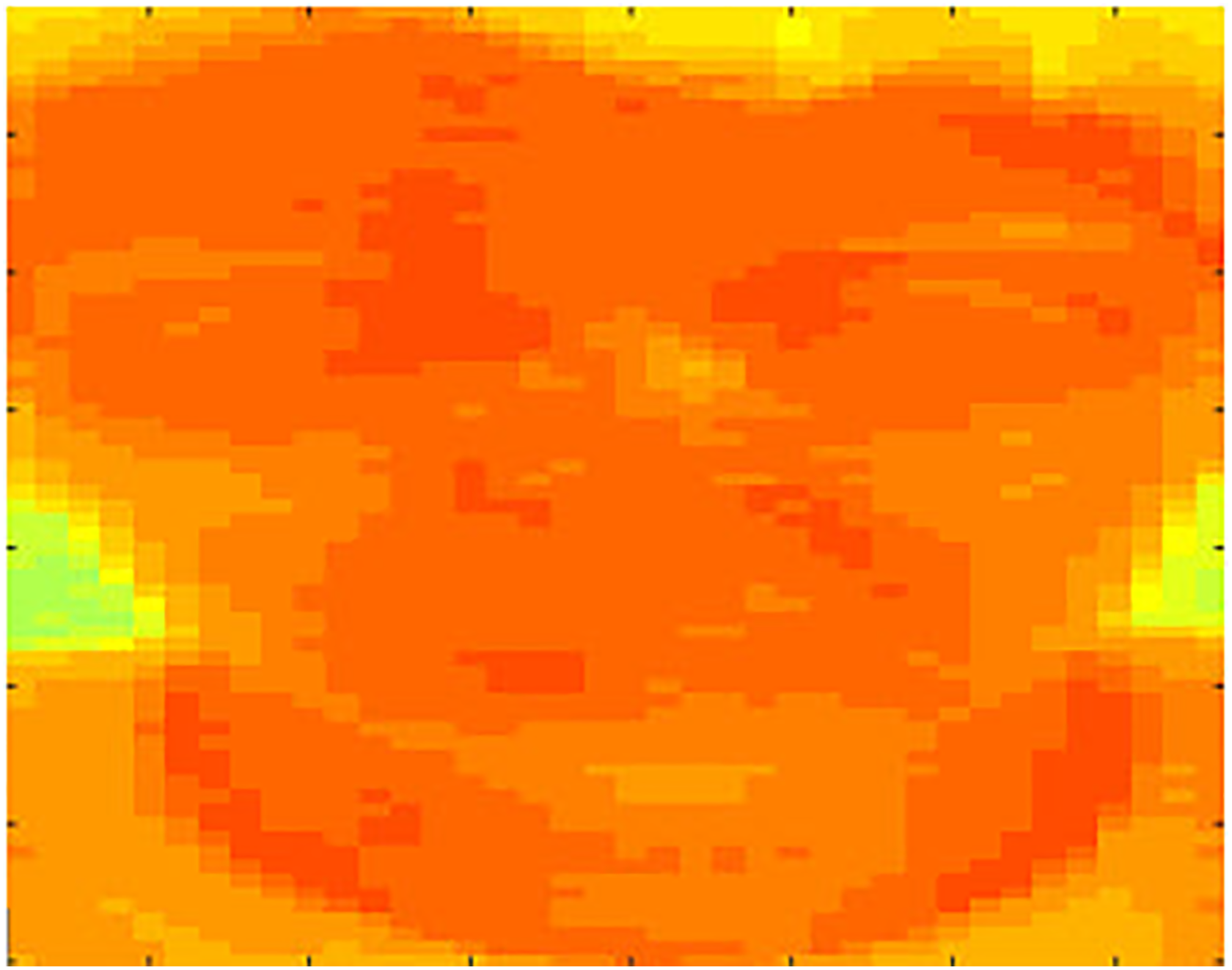
Example face data.
After face images were extracted from the original images, facial images were then processed using two different methods. For the first method, the images were broken up into 16 × 20 grid where the pixels in each block of the grid had its pixels averaged to create 320 values. For the second method, the face was divided into a 12 × 12 grid, and regions were selected as seen in Figure 3 to create a total of 23 regions, each of which then had an averaged value. This method was chosen to determine if IR processing of the facial images could be done without facial region recognition. The two grid values were chosen to compare methods to see how the division of the data would affect the results.

Example of segmentation (dotted lines indicate overlapping regions).
For each method of processing the images, two neural networks were trained. In one setup, the averages were made into single-column matrices and combined to create two matrices for training and verification of the neural network. Five of the nine subjects were used for training of the network, and four were used for verification. In the other setup of neural networks, subjects’ data were randomly mixed to create training and verification data.
Neural networks were developed using MATLAB’s Pattern Recognition training for Neural Networks (nprtool). The training method used was the scaled conjugate gradient method. Neural networks designed will be referred to by numbers to indicate which method was used in their training. Neural Network #1 (NN1) was trained using separate subjects for testing and validation, and the segmentation method was the 16 × 20 grid segmentation. Neural Network #2 (NN2) was trained using a mix set of data from all subjects and used 16 × 20 grid segmentation. Neural Network #3 (NN3) was trained using separate subjects for testing and validation, and the segmentation method used was face region segmentation. Neural Network #4 (NN4) was trained using a mix set of data from all subjects and used face region segmentation.
Figure 4 shows an example setup of the neural networks trained using MATLAB. This figure has 23 inputs for the segmentation method. The inputs (either 23 for facial region segmentation or 320 for the 16 × 20 grid segmentation method) were then sent to a hidden layer consisting of 25 nodes. These nodes would then lead to an output layer, which consisted of four values. The value of each node in the output layer is the corresponding match to a particular emotion, based on the provided training. The sum of the values of each output node sums to 1.

Example neural network layout.
Thermal imaging neural network results
For NN1, a final percent error of 59.1% was found in testing using the data of subjects not included in network development. Table 1 shows the confusion matrix for the testing using the four excluded subjects. For NN2, a percent error of 3.12% was found. Table 2 shows the confusion matrix for the testing performed using the mixed data. Tables 3 and 4 show the confusion matrix for the test data of NN3 and NN4, respectively. NN3 showed a percent error rate of 54.8% with the test data, while NN4 showed a percent error of 6.3%. For all tables, green cells correspond to a match between the output class and the target class, while red cells indicate a mismatch. Grey cells are sums over the rows and columns, and the cell in the bottom right is the average. Green values in the grey cells indicate the rate of positive matches by the NN, while red indicates incorrectly categorized data.
Confusion matrix for NN1 (test data).

NN1: Neural Network #1.
Confusion matrix for NN2 (test data).

NN2: Neural Network #2.
Confusion matrix for NN3 (test data).
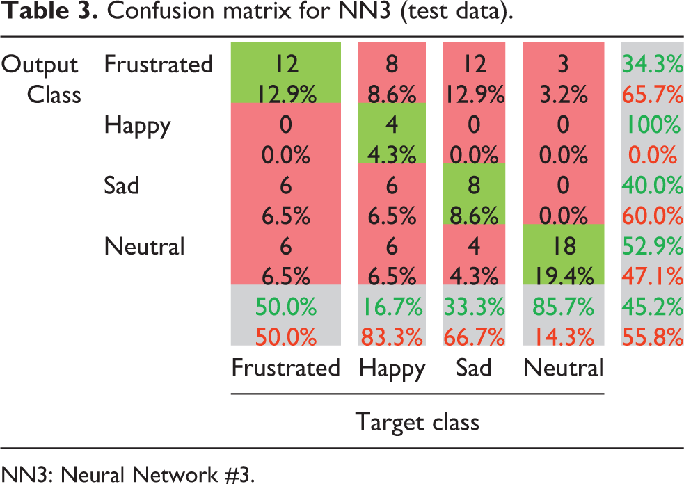
NN3: Neural Network #3.
Confusion matrix for NN4 (test data).

NN4: Neural Network #4.
Kinect v2 experiments
For the Kinect v2 experiments, four subjects were asked to participate. The position of subject’s elbows and wrists was examined separately. For the elbow exercises, subjects were asked to perform seven different gestures: three of these gestures positioned the elbow in a 180° angle, two asked them to create a 90° angle, and one asked subjects to perform a 135° angle with their arm. Subjects were asked to estimate the angle of their joints, and the subject’s perceived angle and the angle measured by the Kinect v2 were recorded. The angle recorded by the Kinect v2 was sent to an Arduino Mega microcontroller, which then moved a stepper motor to recreate that angle. Subjects were asked to estimate the angle created, and this value was also recorded. This was repeated for the wrist measurements, except that only five poses were used for the wrist.
Determination of the joint angles for this experiment was done using the Kinect v2 API. Using the depth camera, the positions of joints were obtained as coordinates in three-dimensional (3D) space. With the positions of the shoulder, elbow, wrist, and hand tip positions, it is possible to generate three vectors. To determine the angle of the elbow joint, the joint positions for the shoulder and wrist positions were used to create two vectors that shared a single origin point of the elbow. Using these vectors, it is possible to solve for the angle using equation (1). Rotation of the shoulder is ignored in this model due to the fact that the model of a limb used was two stepper motors which are not capable of rotation. A similar process is repeated using vectors between the hand tip and wrist and between the elbow and wrist to get the angle of the wrist joint. Again, rotation values for this joint are not considered to simplify the model. Figure 5 shows an example of the joints being tracked in real time, displayed over the feed from the depth camera.


Joint tracking.
Once subjects had completed the angle estimation task, the subject was asked to provide a quantitative assessment of the performance of the motor at mimicking their movement. To do this, voice control was implemented in the C# control program. This was done using the Kinect v2 microphone array and the Kinect Speed Platform SDK. A voice recognition engine was generated to recognize a set series of commands: “fast,” “faster,” “speed up,” “slow,” “slower,” and “slow down.” When these commands are recognized by the controller program, a flag is set and sent to the Arduino control program, which adjusts the motor speeds accordingly.
The subject would then rate the performance of the motor in following their movements when performing a simple waving gesture. Good performance on this task would suggest that the system holds promise for applications such as mirror therapy in limb rehabilitation. Subjects were asked to rate both the accuracy of the motor in tracking their movements and the “shakiness” of the motor at different speeds. Shakiness in the stepper motor comes about from delay in the serial communication involved in the system. If the user makes rapid movements, they may see sudden starts and stops of the motor as it attempts to follow their joints. Users were asked to rate how noticeable this shake was for various speeds. Of interest in this study was if there was a speed that was most often rated as best performing by users, which would be usable as a baseline to adjust in future experiments.
Kinect v2 results
This section focuses particularly on the difference between what users believed they were doing (perceived) and what was actually produced (motor joint angle). For mirroring or teleoperation purposes, it is desirable to have minimal difference between what the user expects of the system and what the system produces, as this visual feedback is the main observable output of the system to the user. Therefore, differences between user expectations and output are worth noting.
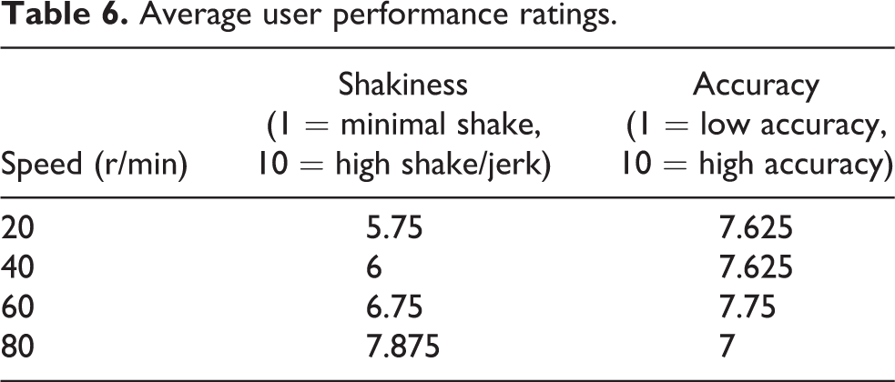
Table 5 shows the average difference between the perceived angle and the recorded angle and the average difference between the perceived angle and the motor joint angle. Although the wrist joint as detected by the Kinect v2 had a lower average difference between what the user perceived as their joint angle and what the C# control program determined was the joint angle, the difference between the subject’s perceived joint position and the stepper joint position was higher for the wrist than for the elbow. Table 6 shows the average values for user-rated accuracy and shakiness of the motor. Both measurements were on a 1–10 scale, where 10 indicated high accuracy and high shakiness in the response of the motor. The results in Table 6 are averaged across all subjects and show that as speed of the stepper motor increased, subjects also noticed an increase in noticeable “jitter” in the response of the motor. However, although accuracy also decreases as speed increased, the accuracy at 60 r/min does not follow this trend.
Joint values.

Average user performance ratings.
Analysis
The results of the two neural networks suggest that there is a high probability of being able to create adaptive systems that will be able to detect user stress. In the example where the validation data involved different subjects than the training data, the neural network was able to achieve results better than guessing, suggesting that with a wider set of samples it may be possible to tune this network to work as a general engine capable of being the foundation of a system for users. However, the networks error rates of 59% and 54% also suggest that a generalized system may not be suited to being the only control system for a device, particularly with an assistive device which may only have a single user or a small group of users and does not need to be generalized to a large population.
The results of the neural networks trained with a mix of data from all subjects had much higher success rates. This suggests that the system is highly successful at recognizing user’s patterns that it has been exposed to before, as would be expected from a pattern recognition network. Future research may be able to tailor a system to a user’s specific emotions. The low-accuracy neural networks previously discussed could be used as a basic system to perform analysis before a more developed network can be created. Because the capturing of images for subjects took very little time and required little effort on the part of subjects, the data necessary to adjust a neural network to be adaptive to a single patient would be minimal and could be done as part of the normal setup of a device.
The Kinect v2 testing showed an interesting result. For the elbow, the difference between the perceived angle of the subject’s joint and the angle identified by the Kinect v2 was about 8°. However, the difference between the perceived angle of the subject’s joint and the motorized joint was about 3°. This suggests that users may not be able to distinguish small changes in their elbow joint. For the elbow, the largest difference was when the subject was asked to estimate a 135° angle with their arm. The error could be due to subjects improperly replicating this angle but suggests that there may be an overall discrepancy between what a subject believes their pose is and what the system sees. Some data from the wrist supports this theory. Although the Kinect data for the wrist was much closer to what users perceived as their wrist angle, the average error for the motor joint versus the human joint was much higher. The largest contributing factor to this were the large errors when users were asked to bend their wrist as close to 90° up or down as they could manage. Even when users did not manage to bend their wrist up 90° (due to it being difficult for most people), they would still rate their own joint angle as being 90°. In addition, it is much easier for a person to identify a right angle then to identify other angles. As a result, we believe subjects were more likely to identify an error in 90° wrist movements and to overestimate their own joint positions when making “known” angles. This should be taken into account when designing future systems, as the system may have to be able to estimate if an angle is “around” a desired angle (0°, 45°, 90°, etc.) and move to that position instead of simply mimicking user motion.
Conclusions
The research presented here suggests potential methods with which to control an automated arm system using an IR camera and the Microsoft Kinect v2. Through use of a neural network and samples of a user’s face data expressing different emotions, it is possible to achieve acceptable accuracy in determining user stress. This can be used to signal a system to modify its behavior to attempt to reduce user stress and meet optimal speed for operation. In addition, the Microsoft Kinect v2 is capable of tracking user joint position in 3D space, and programs can be developed to transform this data into joint angles for a motorized system. Potential applications can result in an adaptive and customizable system that is easily controlled by users and responsive to user action.
Future work should involve the integration of systems to meet the original design plans. The systems were tested separately in this study, and the final goal of combining the two systems for testing was not met. Work for the IR thermal imaging should involve development of real-time or near real-time response. The current implementation requires multiple programs and human operation to do processing. In addition, further experimentation should be done with users on different days and over time to ensure that the high accuracy rates seen by the neural networks developed here are due to patterns of emotion and not other patterns that may be present and identifiable in some way. This may involve gathering more subject data to create a reference database such as the one created by Wang et al. 18 to test against or to improve the general neural networks. Another potential future direction for the IR camera is to investigate low-resolution arrays to achieve similar results. Although the use of low-resolution IR arrays was found not to meet the necessary accuracy of facial temperatures needed for this study, alternative methods may be able to make use of cheaper low-resolution arrays to achieve similar results.
There is also potential work to be done on the Kinect control system. Due to the nature of the two stepper motors used for joint angle testing, the current angles are in a two-dimensional space. Potential improvements would be to use joint rotation data and 3D positional information to control an arm in 3D space. In addition, users are sensitive to perceived errors when their arm is in 90° or 180° position. Potential work could be in identifying when a user is likely to be in one of these positions and to send a corrected joint value instead of an actual joint value. Joint smoothing is another important consideration. The Kinect v2 creates a small amount of jitter when reading position data, and these small disparities can create small shakes in the output that could be a potential issue in uses of this device. Because it is possible to determine the velocity with which joints are changing angle, this can be used to smooth sharp spikes in velocity or small tremors and to provide a smoother and more exact motion for a more natural experience for users.
Footnotes
Declaration of conflicting interests
The author(s) declared no potential conflicts of interest with respect to the research, authorship, and/or publication of this article.
Funding
The author(s) disclosed receipt of the following financial support for the research, authorship, and/or publication of this article: This article is based upon work supported by the Research Experiences for Undergraduates Program under the National Science Foundation grant no. 1263293 and by the Texas A&M University-CONACYT Research Grant Program. Any opinions, findings, and conclusions or recommendations expressed in this material are those of the author(s) and do not necessarily reflect the views of the National Science Foundation or the Texas A&M University-CONACYT Research Grant Program.