
Abstract
This paper presents a FLIR/INS/RA integrated landing guidance method to provide information of aircraft states and carrier dynamics for fixed-wing aircraft landing on the aircraft carrier in low-visibility weather and high sea states. The method utilizes the Forward-Looking Infrared (FLIR) system, the Inertial Navigation System (INS), and the Radio Altimeter (RA) as sensors, to track infrared cooperated targets on the aircraft carrier. Several algorithms like the Newton iterative algorithm, the Kalman Filter (KF), and the Wavelet Transform (WT) are employed to compute real-time and high-precision estimates of the aircraft states (runway-related position, attitude, and velocity) and the carrier dynamics (pitch, roll, and heave). A simulation experiment is conducted and shows satisfactory results for the aircraft carrier landing guidance.
1. Introduction
The landing guidance information is extremely useful for fixed-wing aircraft landing on the aircraft carrier. Considering the complicated landing environment, such as a small landing area and uncertain aircraft carrier dynamics, landing on the aircraft carrier has become one of the most difficult missions [1, 2]. For the safe landing operation, the landing guidance system should provide accurate aircraft states (e.g., position, velocity, and attitude) and the carrier dynamics' (e.g., pitch, roll, and heave) information for the aircraft to plan an optimal descent trajectory and employ a corresponding control strategy [3, 4, 5] in all weather and sea states.
There are many kinds of landing guidance systems for manned/unmanned aircraft. The classical sensor of landing guidance systems is a tracking radar [6] or relative GPS [7], which determines the aircraft state error with respect to a reference trajectory and corrects it by using a robust control law. With the development of the optical technology, visual features used in the landing operation have been studied for several decades for cognitive and safety aspects. Laurent [8] presents a method for carrier landing by using aircraft optical sensors and visual features. Those systems can provide satisfactory landing guidance information in normal weather and sea states. However, in low-visibility weather and high sea states, the darkness or uncertain environment disturbances may weaken the capacity of the pilot to observe the moving runway and track the landing area [9]. Otherwise, electromagnetic interference or communication disconnections may increase the risk of losing guidance information in the alignment and landing phase. Therefore, how to provide precise landing guidance information in those complicated landing environments has become an important topic.
For the purpose of implementing the aircraft landing on the carrier safely and accurately in low-visibility weather, high sea states and an electromagnetic interference environment, an independent and autonomous landing guidance system integrating measurements of FLIR system, INS, and RA is presented in this paper.
First, the FLIR system tracks infrared cooperated targets setting on the deck and estimates the aircraft state and carrier dynamics from 2D-to-3D correspondences between descent images and infrared cooperated targets by using the Newton iterative algorithm. The FLIR system can provide navigation information in low-visibility weather and high sea states, and has already been used for static runway landing [10, 11, 12] and helicopter landing [13].
Second, KF is designed to integrate the FLIR observations and inertial measurements to compute more precise estimates of the aircraft state. KF can lead to excellent estimation accuracy and robustness in the presence of modelling nonlinearities [14, 15, 16], which is suitable for aircraft state estimation.
Meanwhile, WT can also be used to extract the low frequency and slow varying carrier dynamics from FLIR observations. WT is a projection of a signal or a time function onto a 2D time-scale phase plane, which has the local characteristic of a time-domain as well as a frequency-domain and changeable time-frequency windows [17, 18]. In digital signal processing terms, WT can be processed as a low pass filter to the original signal [19], which is suitable for estimating low frequency carrier dynamics with scarce FLIR observation data.
Finally, estimates of the aircraft state and carrier dynamics can be provided to the flight control system to predict the deck motion, compute the deck motion compensation, plan an optimal descent trajectory, and employ a corresponding control strategy.
This paper is organized as follows: Section 2 provides an overview of the FLIR/INS/RA integrated landing guidance system. Modelling of the system is presented in Section 3. Section 4 presents the aircraft state and carrier dynamics estimators and filters: the Newton iterative algorithm, KF, and WT. Simulation experiment results are shown in Section 5. Finally, the conclusion is presented in Section 6.
2. System Overview
The goal of the FLIR/INS/RA integrated landing guidance system is to provide accurate estimates of the aircraft state (the runway-related position, attitude, and velocity) and carrier dynamics (the pitch, roll, and heave) for the flight control system. For this purpose, the Newton iterative algorithm, KF, and WT are employed as estimators.
As mentioned in the introduction, the system utilizes the FLIR system to track infrared cooperated targets setting on the deck and employs the Newton iterative algorithm to estimate the aircraft state and carrier dynamics from 2D-to-3D correspondences between descent images and infrared cooperated targets [20] (see Figure 1).

Infrared cooperated targets applied for landing guidance
When FLIR observations (estimates of the aircraft state and carrier dynamics) are obtained, KF is used to fuse FLIR observations with measurements of INS and RA to obtain accurate estimates of the aircraft runway-related position, attitude, and velocity. RA measurements should be handled by the Finite Impulse Response filter (FIR) to decrease the effect of waves and subtract the height of the static deck to the sea level. Meanwhile, WT is used to extract efficient carrier dynamics information from FLIR observations for the Flight Control System (FCS).
Estimates of the aircraft state and carrier dynamics are provided to FCS to compute the Deck Motion Compensation (DMC) and the flight control command. The control strategy is designed as follows: (1) The carrier pitch, roll, and heave are used to predict the deck motion at the expected landing time; (2) DMC is computed based on the deck motion prediction and then used to modify the reference trajectory; (3) FCS computes control commands and control aircraft movements, by using aircraft state feedbacks (velocity, attitude, and the error of the aircraft position, with respect to the modified trajectory). State feedback gains can be computed by using the optimal LQ method [21].
The whole landing guidance system block diagram is presented in Figure 2.
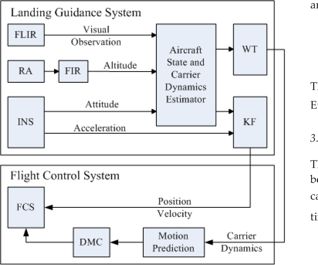
System block diagram containing constructions of the landing guidance system and the flight control system
3. Modelling
This section presents models used in aircraft state and carrier dynamics estimators, which are the optical projection model from the infrared cooperated target to its homologous image point, the carrier motion model, and the aircraft motion model.
Figure 3 represents the different frames involved. The Earth is assumed to be flat, considering the Earth's radius and the study range. The x-axis of the plane frame FO is North-East-Down oriented. The aircraft body frame FB and the carrier body frame FS are conventionally designed with the z-axis oriented down. The carrier runway frame FR corresponds to the origin of the carrier deck, translated and rotated about its z-axis from the carrier frame, which is expressed by the constant known matrix SRR and the offset vector SRT. The camera frame FC corresponds to the origin of the aircraft, translated and rotated about its x-axis from the aircraft body frame, which is expressed by the constant known matrix CBM and the offset vector CBT. The pose vectors of the aircraft and the carrier in FO are respectively defined by:

Frames involved in the landing guidance method
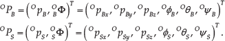
and

The orientation matrices BOΦ, SOΦ are represented using Euler angles, where BOΦ can be provided by INS.
3.1 Optical Projection Model
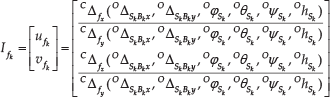
The optical projection model describes the relationship between the coordinate of infrared cooperated target in the camera frame CΔf and its homologous image point Ifk at time tk. The perspective projection model is expressed by:

where

where Opfk is the pose of the infrared cooperated target setting in FO, and Opck is the pose of the aircraft camera in FO at time tk. Motions of Opfk and Opck are described by the carrier motion model and the aircraft motion model, respectively.
3.2 Carrier Motion Model
The carrier motion model describes the infrared cooperated target motion affected by the carrier velocity, yaw, roll, pitch, sway, surge, and heave.
The infrared cooperated target motion equation can be written in block-form as:

where Opfk is the pose of the infrared cooperated target in FO at time tk, OpS0 is the initial pose of the carrier, OvSk is the carrier velocity, SORsk is the orientation matrix from FS to FO (the carrier yaw
Sk
pitch, and roll are respectively defined by φSk, θSk and ψSk) at time tk, Rpf is the coordinate of infrared cooperated targets in FR,
3.3 Aircraft Motion Model
The aircraft motion model describes the camera motion affected by the aircraft velocity yaw, roll, and pitch. Since the orientation matrix Rbc and the camera pose Bpc in aircraft body frame (equal to BCT) are calibrated and constant, the camera motion equation can be written in block-form as:

where Opck is the pose of the aircraft camera in FO at time tk, OpB0 is the initial pose of the aircraft in FO, OvBk is the aircraft velocity, BORBK is the orientation matrix from FB to FO (the aircraft yaw, pitch, and roll are respectively defined by φBk, θBk and γBk) at time tk.
4. Estimator Description
This section describes the aircraft state and carrier dynamics estimator (the Newton iterative algorithm) and filters (KF and WT).
4.1 The Newton Iterative Algorithm
The Newton iterative algorithm is employed as the aircraft state and carrier dynamics estimator to estimate the aircraft runway-related position, velocity, and attitude, and the carrier pitch, roll, and heave, by minimizing the error between the coordinate of the camera CΔfk and its homologous image point Ifk determined by the optical projection model (1).
Instantiating (3) and (4), the Equation (2) can be rewritten as:

where OΔSkBk is the aircraft runway-related position in FO, S p f =RSR· R pf+RST is the infrared cooperated target coordinate in FS.
OΔ Sk Bk is expressed as:

Note that some parameters are already known or measured: K, BCR, Spf and CpB are already calibrated and constant, OBRBk is provided by INS, OpBk z and OvBk z are provided by RA, OpSk z and Ovskz are equal to OhSk and OhS. Equations (1) and (2) can be expressed as the nonlinear Equation (7) with unknown parameters: OΔSkBkx′, O ΔSkBky, OφSk, OθSk, OψSk and OhSk.
The Newton iterative algorithm uses the iterative equation (ω, t)k +1 = (ω, t) k -Δ to solve Equation (7) and obtain parameters O Δ Sk Bkx , O Δ Sk Bky , O φ Sk , O θ Sk , O ψ Sk and O h S , where (ω, t) k means the k times iterative result Δ is calculated by Δ = (Ja Tc · Jac)−1 · JTa c · If, where Jac is the Jacobi matrix calculated by the Equation (8):
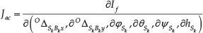
By giving the initial iterative result (ω, t)0, Δ will be reduced to the minimum and the (ω, t) k will approach to the best result. In order to improve the iterative speed and the result's precision, all parameters are initialized to common values in the aircraft-landing phase. For example, OΔ Sk Bk x and OΔSkBky are respectively initialized to 1500m and 100m which are usual poses when the aircraft is starting to land, φSk is initialized to φBk, and θSk, ψSk, hSk are initialized to zero, which are regression values of carrier motion dynamics.
After obtaining OφSk, the aircraft runway-related yaw OφSk Bk can be estimated by:

The aircraft runway-related lateral and longitudinal velocities can be estimated through Equation (10):

4.2 Kalman Filter
KF is utilized to fuse FLIR observations, INS, and RA measurements to compute accurate estimates of the aircraft state (runway-related position, velocity, and attitude).
Each time the current aircraft state is estimated, the KF state vector and covariance estimates are updated.
The structure of the KF state vector is expressed as:

where RpTB and RvTB are the aircraft runway-related pose and velocity of the aircraft, RaTB is the aircraft runway-related acceleration, BRqT is the Euler angle vector describing the aircraft's attitude, bgT and baT are 3×1 vectors that describe the biases affecting the gyroscope and accelerometer measurements and are modelled as random walk processes. Note that the carrier acceleration O aST≈0 in the aircraft-landing phase, RaTB is considered to be equal to the aircraft plane-related acceleration OaTB.
The model for the evolving state vector is given by
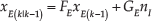
where nI is INS noise, which depends on the system noise characteristics and is computed offline during sensor calibration, the matrices FE and GE appear as:

and

where I3 is the 3×3 identity matrix, Δt is the system sampling time,
The observation is described by the Equation (13):

where zE(k)=[
R
p̂BT Rv̂TB RBq̂
T
]T is the FLIR observation of the aircraft runway-related position, velocity, and attitude, nO is the 9 × 1 observation noise vector with covariance matrix
The observation Equation (13) is employed for performing KF updates as described.
4.3 Wavelet Transform
The efficient estimates of carrier dynamics are required for maritime operations, especially for safe landing operations [22, 23, 24]. For control purposes, accurate prior knowledge of carrier pitch, roll, and heave motions will improve the efficiency of carrier motion prediction, the deck motion compensation, and optimal landing trajectory plan.
Note that since the carrier dynamics are common in representing sea states as a superposition of sinusoidal forms covering a wide range of wave frequencies by abnegating high-frequency components [25], it can be approximated as a superposition of sinusoidal waves:

where Ai, ωi and bi are the amplitude, frequency, and phase of carrier dynamics, respectively.
Considering Ai, ωi and bi are time invariant constants (or vary sufficiently slowly over time), WT is used to de-noise the carrier dynamics estimates.
The wavelet basis functions ψa,b(t) are obtained by translations and dilation of the mother wavelet ψa,b(t).

where a is the scale parameter, and b is the time translation parameter. By the given wavelet basis function, the equation of Continuous Wavelet Transform (CWT) is given as:

WT is processed as a low pass filter to the FLIR observations (carrier dynamics). The schematic diagram of the WT process is shown in Figure 4.

The process of the Wavelet Transform at level three for signal de-noising
In Figure 4, A, AA, and AAA are approximate sections of the noised signal S, and D, AD, and AAD are detailed parts. With the process of WT, the signal is reconstructed, and the purpose of de-noising is achieved.
5. Simulation
In order to validate the performance of the FLIR/INS/RA integrated landing guidance system in conditions as close to actual aircraft landing as possible, a simulation experiment is conducted. The experiment considers a moving carrier at 20 knots (about 10.3 meters per second) with classic carrier dynamics conditions: which are 2° peak-to-peak value of carrier pitch, 0.6° of carrier roll, 1.8m of carrier heave, and 0.3 to 0.6 rad/sec of carrier dynamics frequency ranges. The aircraft is initialized at about 1500m from the carrier, with 100 and 240 meters of the aircraft's vertical and lateral shifts. Errors of instrument measurement, air turbulence, and other environment parameters are also considered in this experiment.
5.1 Aircraft State Estimates
The aircraft state estimates contains aircraft runway-related position, attitude, and velocity estimates, which are computed by the Newton iterative algorithm and KF.
1. Aircraft position estimate
Errors of aircraft runway-related position estimates are shown in Figure 5. As presented in Figure 5, at 800m away from the carrier, the aircraft longitudinal distance error is reduced to 5m, and aircraft lateral and vertical distance errors are reduced to 1m.
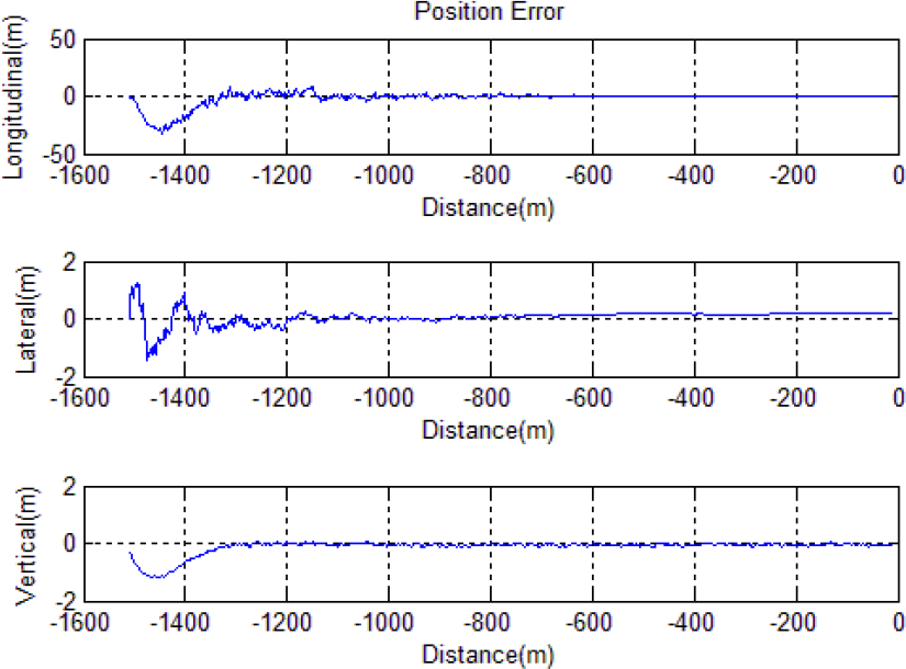
Time evolution of position estimate error (meters) between the aircraft and the impact point of carrier
2. Aircraft attitude estimate
Errors of aircraft runway-related yaw, pitch, and roll estimates are shown in Figure 6. As presented in Figure 6, at 800m away from the carrier, aircraft runway-related yaw, pitch, and roll estimate errors converge to 0.1°.

Time evolution of attitude estimate error (degrees) between the aircraft and the impact point of carrier
3. Aircraft velocity estimate
Errors of aircraft runway-related velocity estimate are shown in Figure 7. As presented in Figure 7, at 800m away from the carrier, the aircraft velocity estimate errors converge to 1m/s.

Time evolution of velocity estimate error (meters per second) between the aircraft and the impact point of carrier
These results of aircraft state estimate show a very good estimation performance of the aircraft state estimator and KF. These estimates can be directly applied for precision guidance and control during landing.
5.2 Carrier Dynamics Estimates
The carrier dynamics estimates contains carrier pitch, roll, and heave estimates, which are computed by the Newton iterative algorithm and WT.
1. Carrier roll estimate
The carrier roll estimate and estimate error are shown in Figure 8. As presented in Figure 8, the estimate error of carrier roll converges to 0.05° at 800m away from the carrier.

(a) Time evolution of roll estimate (degrees) between the aircraft and the impact point of the carrier; (b) Time evolution of roll estimate error (degrees) between the aircraft and the impact point of the carrier
2. Carrier pitch estimate
The carrier pitch estimate and estimate error are shown in Figure 9. As presented in Figure 9, the estimated error of carrier pitch converges to 0.05° at 800m away from the carrier.

(a) Time evolution of pitch estimate (degrees) between the aircraft and the impact point of carrier; (b) Time evolution of pitch estimate error (degrees) between the aircraft and the impact point of carrier
3. Carrier heave estimate
The carrier heave estimate and estimate error are shown in Figure 10. As presented in Figure 10, the estimated error of carrier heave converges to 0.1m at 800m away from the carrier.

(a) Time evolution of heave estimate (meters) between the aircraft and the impact point of carrier; (b) Time evolution of heave estimate error (meters) between the aircraft and the impact point of carrier
These results of carrier dynamics estimates show a satisfactory estimation performance of t he Newton iterative algorithm and WT. These estimates can be applied for deck motion prediction, DMC computation, and flight control during landing.
6. Conclusion
This paper presents the analysis and simulation experimental validation of a landing guidance system combining the FLIR system, INS, and RA for the aircraft carrier landing operation. The system utilizes FLIR system, the Newton iterative algorithm, KF, and WT to track infrared cooperated targets on the carrier and compute real-time and high-precision aircraft runway-related position, velocity, attitude, and efficient carrier pitch, roll, and heave. A simulation experiment, covering the dynamics profile of a typical carrier landing task, shows satisfactory estimate errors of magnitude 5m in the aircraft longitudinal position, 1m in the aircraft lateral position, 1m in the aircraft vertical position, 1m/s in aircraft velocity, 0.05° in carrier roll, 0.05° in carrier pitch and 0.1m in carrier heave estimates at 800m away from the carrier. These results vastly improve the current state of visual/inertial integrated landing guidance systems, and meet the requirements of the carrier landing operation.
Footnotes
7. Acknowledgements
This work was supported by the National Natural Science Foundation of China (no. L142200032), the Long-term Development Strategic Research of Chinese Engineering Science and Technology (no.2014-zcq-01), and the Graduate Innovation Practice Foundation of BUAA through grant YCSJ-01-2014-10.