
Abstract
The objective is to define optimal orientation of gripping device with minimal gripper energy consumption, having preset parameters of manipulator, Bernoulli device, object of manipulation and its path. The division of the arc into three sections—speed-up, steady motion, slowing-down—is presented. The optimal orientation is defined in any point of time on each section, which is defined using inertial and gravity forces as object of manipulation retention force with gripping device. Problem solution for a specific example, providing continuous transportation along the whole path for the object of manipulation, is introduced. The effectiveness of using this method of object transportation along the arc is proved. The energy efficiency of the implementation of the optimization orientation method was 41% for the example given.
Keywords
Introduction
Industrial robots for transportation of the objects of manipulation along different paths are widely used in modern production. Energy cost reduction for holding the object of manipulation with gripping devices in the process of movement along the arc is a topical issue. In gripping devices of Bernoulli kind, 1 –8 lifting force is created on account of aerodynamic effect of attraction which is provided by the compressed air usage. The method of object transportation along cylindrical-spiral path and its optimization with decreasing of end link vibrations are described in the paper. 9 The method of Bernoulli gripping device orientation along linear path with shifted mass center of the object of manipulation is introduced in the articles. 10 –12 The restriction on movement parameters and lifting capacity during the movement for different orientation of Bernoulli devices are given in the articles. 13 –15
In Shiller’s article, 16 the motions of articulated systems along specified paths are optimized to minimize a time–energy cost function. The optimization problem formulated is a reduced two-dimensional state space and solved using the Pontryagin maximum principle. The optimal control is shown to be smooth, as opposed to the typically discontinuous time optimal control. The smoother time–energy optimal trajectory is shown to result in smaller tracking errors than the time optimal trajectory.
The motion of current industrial manipulators is typically controlled, so that tasks are not done in a minimum time optimal manner. The result is substantially lower productivity than that potentially possible. Recently, a computationally efficient algorithm has been developed to find the true minimum time optimal motion for a manipulator moving along a specified path in space that uses both the full nonlinear dynamic character of the manipulator and the constraints imposed by its actuators. A Computer-Aided Design implementation of the algorithm called Optimal Time Control of Articulated Robotic Manipulators (OPTARM) is described in article 17 which can treat practically general six degree-of-freedom manipulators. Examples are presented which show OPTARM to be a useful design tool for manipulators, their tasks and work places. The algorithm is extended in OPTARM to include the constraints imposed by manipulator payloads and end effectors.
Chettibi et al. 18 discuss the problem of minimum cost trajectory planning for robotic manipulators. It consists of linking two points in the operational space while minimizing a cost function, taking into account dynamic equations of motion as well as bounds on joint positions, velocities, jerks, and torques. This generic optimal control problem is transformed, via a clamped cubic spline model of joint temporal evolutions, into a nonlinear constrained optimization problem which is treated then by the sequential quadratic programming method. The Peng and Akella 19 focused on the collision-free coordination of multiple robots with kino-dynamic constraints along specified paths. Also, presented an approach to generate continuous velocity profiles for multiple robots; these velocity profiles satisfy the dynamics constraints, avoid collisions, and minimize the completion time. The approach, which combines techniques from optimal control and mathematical programming, consists of identifying collision segments along each robot’s path, and then optimizing the robots’ velocities along the collision and collision-free segments.
Presented a novel approach to kino-dynamic trajectory generation in paper, 20 for noncircular omnidirectional platforms that can be combined with existing path planners and used quintic Bézier splines to specify position and orientation of the holonomic robot for every point in time. To fully exploit the capabilities of the robot, we propose a novel path representation. It allows for continuous variation of path shapes in the spectrum between straight-line paths with turns on the spot and smooth paths with independent rotations and translations. Using this representation, our method optimizes trajectories according to a user-defined cost function, considering the constraints of the platform. This way, it generates fast and efficient trajectories in an anytime fashion. The experiments carried out on an industrial robot show that our approach generates highly efficient and smooth motion trajectories that can be tracked with high precision and predictability.
However, the question of modeling the dynamic interaction of gripping devices with the object of manipulation in the process of performing an industrial robot of transport and loading operations has been studied inadequately. There is no research to find technical solutions and approaches for reducing energy consumption for holding objects of manipulation using Bernoulli gripping devices, which would ensure the minimum energy consumption of the capture device.
The aim of this research is to find rational orientation of gripping device during its transportation along the arc, which will provide minimal energy consumption for holding the object of manipulation with gripping device.
Methodology
Let’s look at such case of transportation of flat parts (plates) using Bernoulli device shown in Figure 1(b). The operating principle of this device is presented in Figure 1(a). The movement along given arc is performed with a help of manipulator ABB IRB 4600-20, which has six degrees of freedom. Movement programming and simulation of gripping device with the object of manipulation is done using RobotStudio software (ABB group, Zürich, Switzerland). 21

(a) Operating principle for noncontact transportation: (A) compressed air, (B) air flow, (C) lifting capacity, and (D) object; (b) Bernoulli gripping device.
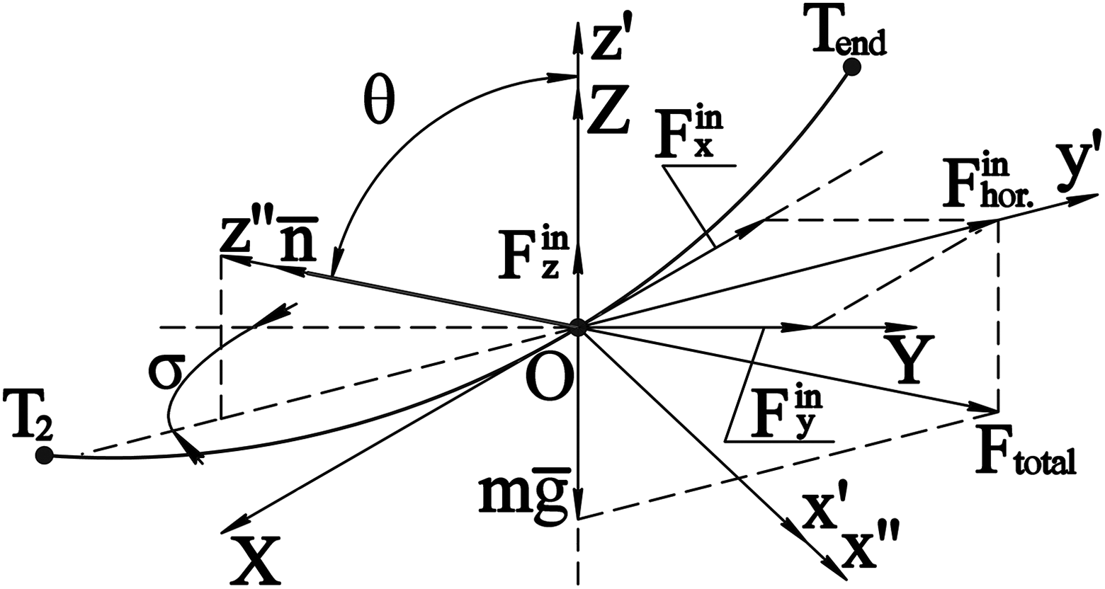
The orientation of gripping device is defined with vector direction

Euler angles for defining vector orientation
It’s obvious that this direction may be defined using two Euler angles: ψ—precession angle and θ—nutation angle. The angle of intrinsic rotation φ doesn’t affect vector orientation
The angle ψ is an angle which is defined from the axis OX toward the line of nodes Ox′ where the axis OX will move after turning of the coordinate system around the axis OZ on the angle ψ (it is calculated in counterclockwise direction when looking in the positive direction of the axis). It’s obvious that this ψ angle is equal to the angle defined from negative semi axis Y toward normal line projection
Angle is an angle of turn around the line of nodes Ox′. It’s positive direction is defined in counterclockwise direction when looking from the positive direction Ox′.
Description of the arc
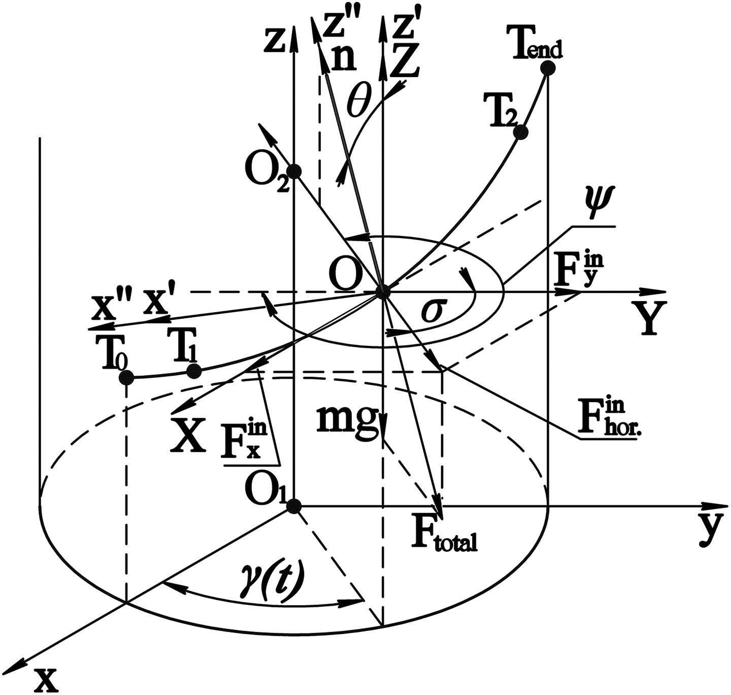
The law of center-of-mass motion of the object of manipulation along the arc (Figure 3) is given by

where γ(t)—some time function, R—radius of the arc, and k—coefficient which defines the value of vertical movement of the object of manipulation.

The arc which orientation optimization of the gripping device is done for.
Center-of-mass velocity of the object of manipulation may be found using the following formula


Similarly for speed-up

where
Let’s look at the first path section T 0−T 1, where the object of manipulation speeds up in a time 0 ≤ t ≤ t 1. For this section, we have
When integrating twice with initial conditions

On the point T 1 when t = t 1, we have

The steady motion of the object of manipulation in the time t 1 ≤ t ≤ t 2 takes place on the second path section T 1–T 2. For this section, we have

When integrating twice and providing continuity ω and γ when t = t 1, we have

Slowing-down takes place on the third path section T 2–T end in a time t 2 ≤ t ≤ t end. For this section, we have
When integrating twice and providing continuity ω and γ, when t = t 2, we have

From the specifications t = t end, γ = π/2, we have
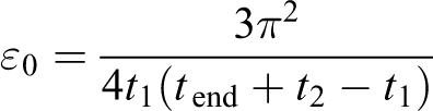
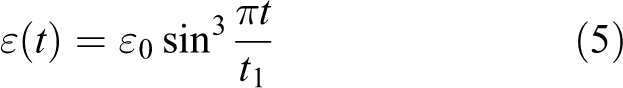
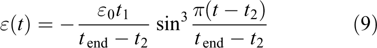
If speed-up time is equal to the slowing-down time—when t end − t 2 = t 1—than the following values should be taken ε(t), ω(t) and γ(t)

After substituting the values ε(t), ω(t), and γ(t) for each section (equations (5) to (10)) in the equation (4), the value of inertial force may be found

The inertial forces (equation (12)) produce an effect on the object of manipulation during the whole period of transportation. Calculations are made using the following parameters: m = 1 kg, t 0 = 0 s, t 1 = 0.4 s, t 2 = 1.5 s, t end = 1.9 s, z = 0.5 m, R = 0.8 m, and the results are shown in Figure 4.

The graph of the inertial force dependence on the time.
Figure 4 shows that during the transport of a gripping device by an object of manipulation along the arc trajectory, there are inertial forces not only during acceleration and deceleration but also during a uniform movement. This is because during transport of the object in the trajectory arc appears centrifugal force acting on the object of manipulation and is identical on the section trajectory of uniform motion T 1–T 2.
Defining optimal orientation of Bernoulli gripping device
Optimal orientation will be provided when the axis of gripping device in any point of time will be directed in the opposite direction to the vector of resultant inertial forces and gravity force. It is related to the fact that lifting force is directed in the direction opposite to
The following components of inertial forces

Forces, which influence on the object of manipulation during speed-up on the path section T 0–T 1.
Therefore,

In order to define θ, it is necessary that projection

As the orientation of contact points in regard to the local coordinate system (XOY) is not changed, the value of angle φ won’t be changed.
On the second section, where the movement is steady (Figure 6), the optimal orientation may be defined the same way.
Forces, which influence on the object of manipulation with steady speed on the path section T 1–T 2.
Figure 6 shows that the value of precession angle ψ on the path section T 1–T 2 will be changed directly to the law γ(t), and it will get the value

where

As ε(t) = 0 is on this path section, then nutation angle is equal to

Let’s take a look at the third path section of slowing-down (Figure 7) which is equal to the section T 2–T end.
Forces, which influence on the object of manipulation during slowing-down on the path section T 2–T end.
The angle ψ on the slowing-down section T 3–T 4 is defined from the equation

where

The angle θ (on the third section) is defined the same as on the first section and gets the following value
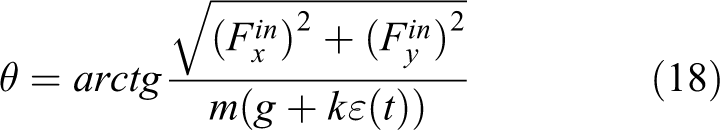
The equations (13) to (18) define optimal orientation of the gripping device in any point of time (Figure 8).
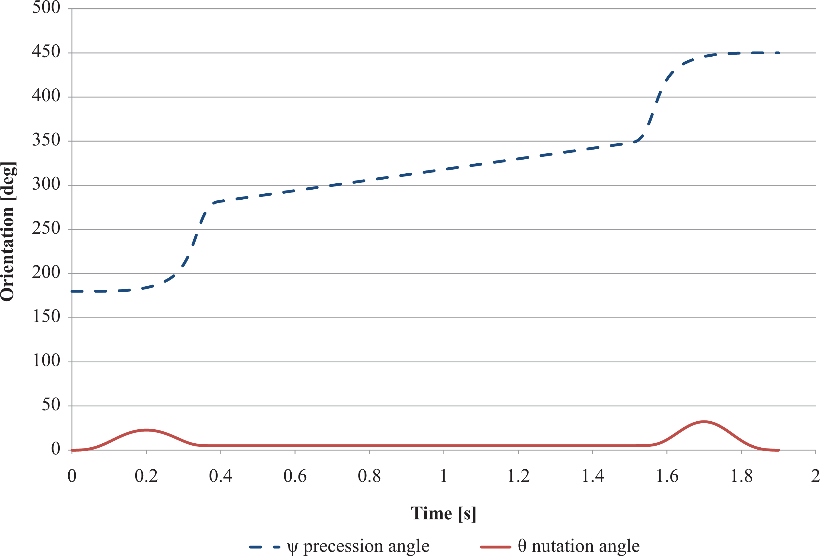
The graph of changing optimal orientation during the whole transportation period.
Defining minimal required lifting force
Being aware of optimal orientation in any point of time, the minimal required lifting force during the whole transportation period should be defined. Equilibrium conditions of the object of manipulation held with the gripping device should be written down (Figure 9)


Forces, which influence on the object of manipulation (N 1, N 2, N 3—normal reactions, F 1, F 2, F 3—frictional forces).
After analyzing the equations (19) to (21) to define minimal required lifting force, it’s necessary to have condition N total ≥ 0, which provides continuous transportation of the object of manipulation. On the basis of the equation (21), restrictions on the minimal lifting force for transportation of the object of manipulation along the arc with optimal orientation may be found (Figure 10)

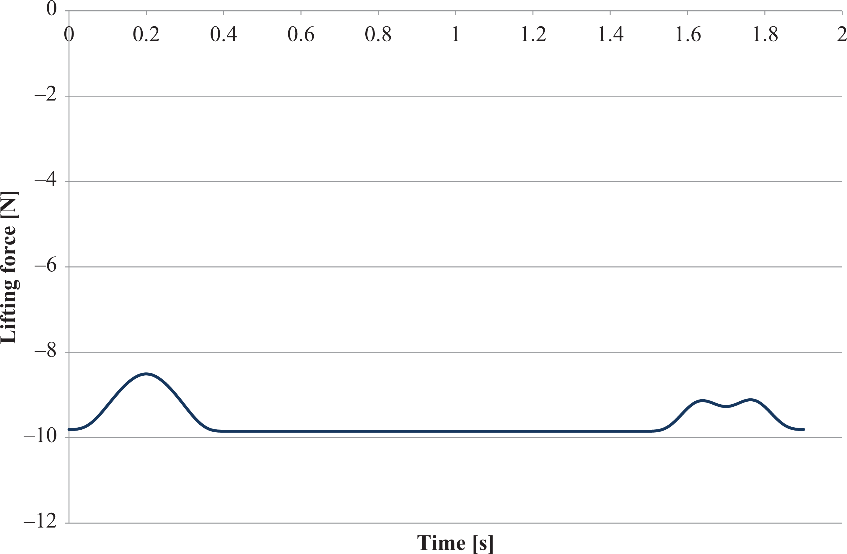
The graph of dependence of minimal required lifting force on the time of transportation, using the method of orientation optimization during object manipulation (OM) transportation along the arc.
Figure 10 shows that the lifting force may not be used if using the method of orientation optimization for transportation of the object of manipulation along the arc. It will allow decreasing energy consumption on transportation of the objects of manipulation with Bernoulli devices.
Intercomparison of transportation methods with and without orientation optimization
If the transportation of the object of manipulation is conducted without optimization, it is transported in parallel with the local plane XOY and does not change orientation during the whole transportation period (Figure 11).
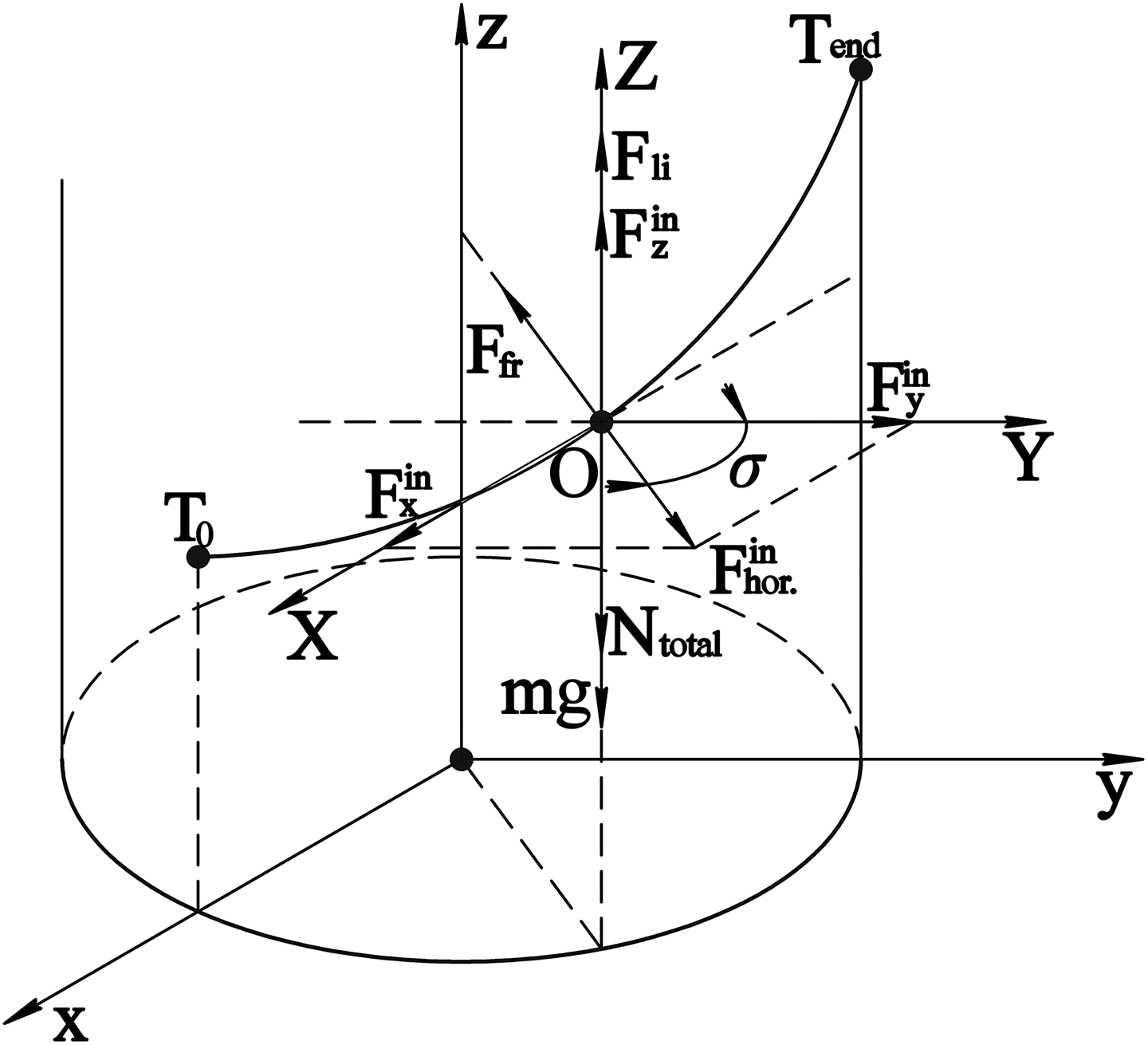
Forces, which influence on the object of manipulation during transportation without reorientation.
Equilibrium conditions for three path sections should be written down: First section (speed-up)


Second section (steady motion)

Third section (slowing-down)
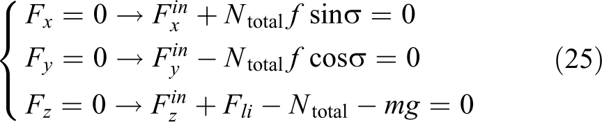
If we define total normal responses Ntotal of the object of manipulation with gripping device from equation system (26–25) and use in Fz , restrictions on the minimal required lifting force for holding object manipulation (OM) with gripping device on each path section (Figure 12) will be found


The graph of minimal required lifting force during transportation without reorientation.
As a rule, the lifting force, during transportation of the objects of manipulation, is fixed with equal maximum value of the lifting force during all transportation period on the whole section. The biggest value of lifting force is required on the speed-up section of gripping device. In this case, the minimal required lifting force 20 N should be provided during OM transportation without reorientation.
For instance, let’s take technical parameters of NCT-100 Bernoulli device of Bosch Rexroth Company 6 to provide lifting force 20 N and required pressure 2.4 bar. With this pressure, compressed air flow will be equal to 130 min−1. Having data required for holding the object of manipulation, energy consumption may be calculated (Figure 13) to provide continuous transportation for transportation with and without optimization

where Pr—rail pressure, Q—compressed air consumption through the slot of gripping device, and Nc—consumption capacity of Bernoulli gripping device.

The graphs of energy consumption by gripping device and industrial robot.
The results of energy consumption by manipulator are received from license software environment RobotStudio of ABB group company 21 for transportation of the OM along the arc with orientation optimization and without reorientation (Figure 13).
Figure 13 shows that the gripping device transporting an object of manipulation with optimization orientation does not consume energy, and without reorientation consumes the same as an industrial robot. Since an industrial robot transporting an object of manipulation with optimization of orientation, performs orientational motions, it spends 19% more energy than when transporting without reorientation.
It is necessary to sum-up energy consumption of manipulator gripper system when transporting the object of manipulation along the arc in two ways (Figure 14).

The graph of total energy consumption by gripping device and industrial robot.
It turned out that 1937 J of energy were used for transportation without reorientation, and 1140 J of energy were used with orientation optimization. It is 41% (797 J) less than such system uses without reorientation.
The influence mass of object of manipulation on the minimum necessary lifting force is investigated (Figure 15). Calculations are made using the following parameters: t 0 = 0 s, t 1 = 0.4 s, t 2 = 1.5 s, t end = 1.9 s, z = 0.5 m, and R = 1 m.

Graph of minimal required lifting force of the gripping device depending on the time at different mass of the object.
The graph (Figure 15) shows that with increasing the mass of the object of manipulation, the minimal lifting force during transportation without reorientation increases. And in the case of using the optimization model of the orientation, the minimum required lifting force is reduced by increasing the mass of the object of manipulation. This has a positive effect on the energy costs of transportation.
Also, the radius of the trajectory has a significant effect on the minimum required force of lifting (Figure 16). Calculations are made using the following parameters: m = 1 kg, t 0 = 0 s, t 1 = 0.4 s, t 2 = 1.5 s, t end = 1.9 s, and z = 1 m.
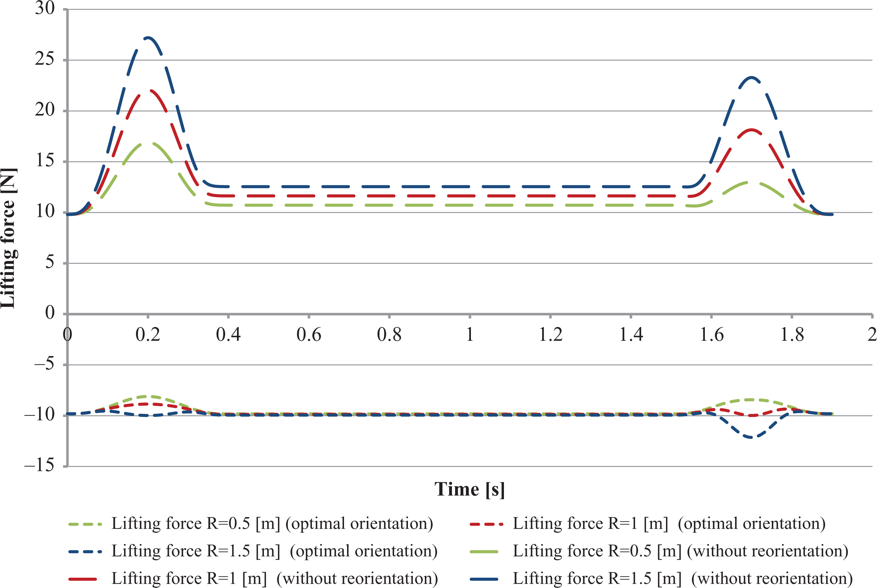
Graph of minimal required lifting force of the gripping device depending on the time with different radius of the trajectory.
Obviously, an increase in the radius of the trajectory will negatively affect the minimum required lifting force during transportation without reorientation. Because with the increasing radius centrifugal force of inertia increases proportionally. For the optimization method, the impact will be positive, as the required lifting force decreases. But this also has its own disadvantage when transporting easily-deformed objects. Since the forces that are acting on the object of manipulation are increasing.
The height of the trajectory lift also has its effect on the minimum required force of lifting (Figure 17). Calculations are made using the following parameters: m = 1 kg, t 0 = 0 s, t 1 = 0.4 s, t 2 = 1.5 s, t end = 1.9 s, and R = 1 m.

Graph of minimal required lifting force of the gripping device depending on the time with different height of the trajectory lift.
From Figure 17, we can conclude that during the increase in the height of the trajectory lift, the minimum required lifting force increases during transportation without reorientation. But this happens only in the area of overclocking the object of manipulation. The minimum required lifting force, on the contrary, decreases during deceleration. So it turns out that in parts corresponding to acceleration and deceleration, the component of the force of inertia F z acting in different directions. With increasing height of the trajectory lift, the minimum required lifting force increases, during transport using the optimization orientation method.
By conducting an experimental verification of the model, it was investigated that when using this method of optimizing orientation for an arc trajectory, the force of lifting is unnecessary. But since the speed of the change of orientation is rather high, it is necessary to choose the maximum possible time for acceleration and deceleration.
The disadvantage of this model is that it does not take into account the displaced center of mass of the object of manipulation. This topic will be investigated in further research.
Conclusion
The method of orientation optimization for Bernoulli device during transportation of the object of manipulation along the arc is introduced. The minimal required lifting force during the movement of gripping device on such path, in case of transportation without reorientation and with orientation optimization, is defined. It is proved, that transportation with a use of optimal orientation decreases energy consumption to 41%, compared to transportation without reorientation.
Footnotes
Declaration of conflicting interests
The author(s) declared no potential conflicts of interest with respect to the research, authorship, and/or publication of this article.
Funding
The author(s) disclosed receipt of the following financial support for the research, authorship, and/or publication of this article: This work was supported by Slovak National Grants Req-00347-0001, VEGA 1/0065/16, APVV-16-0006, and VEGA 1/0752/17.