
Abstract
The dynamics of the air flow between interacting surfaces of Bernoulli–vacuum gripping device and object of manipulation is analysed. The methods of increasing lifting capacity in given devices are presented. The equation for defining pressure distribution in between interacting surfaces of gripping device and object of manipulation and equations for calculation of power characteristics is calculated. The results of theoretical researches of Bernoulli–vacuum gripping devices with different forms of active surfaces are introduced.
Introduction
When solving problems of automation of machined parts handling on certain machines and transfer lines, non-contacting pneumatic grippers are becoming more widely used. 1 Their specific feature is high reliability and durability, low production price, non-contacting grip and holding the objects of manipulation (OM), blanks and parts regardless of their material, mechanical characteristics, surface layer structure and temperature.
Non-contacting pneumatic grippers of industrial robots and manipulators have a range of advantages. However, there are no detailed theoretical and experimental researches in this area, which would lead to the creation of grippers with bigger carrying capacity, reliability in work and high speed of response. The analysis of scientific papers 2 –4 shows that the issue of improving the design of non-contacting pneumatic grippers aimed at providing high performance is of a low priority. The last fact is also confirmed by the analysis of designs and characteristics of Bernoulli gripping devices (BGDs), which are produced by famous foreign corporations (Bosch Rexroth, Schmalz, SMC Pneumatics, Festo). 5 –8 The Mechatronic Systemtechnik GmbH works on the design of Bernoulli–vacuum gripping devices that combine Bernoulli principle and vacuum grippers. 9 Also, a similar principle of work is proposed in the article. 10,11 In an earlier work, 12 the values of the optimal outer diameter for a range of supply mass flow rates were calculated. In another work, 13 a flexible, multifunctional gripper for handling variable size, shape and weight of unpacked food products is discussed.
A study by Dini et al. 14 proposes the use of contactless grippers instead of more traditional vacuum cups or fingered grippers. In particular, the main objectives of this investigation are to measure the performance of different gripper configurations whose lifting force is generated by a high-speed air flow passing between the gripper and the leather ply and to analyse the dynamics of air flow in ejector and in between interacting surfaces of Bernoulli–vacuum gripping device and OM that defines the methods of increasing lifting capacity in given devices. This work also presents mathematical models, analyses force characteristics of Bernoulli–vacuum gripping devices with different forms of active surfaces and explains the choice of the most reasonable designs.
Design and operating principle of Bernoulli–vacuum gripping device
In comparison with vacuum gripping devices, the specific features of Bernoulli devices are high reliability and durability, objects’ locating accuracy and high dynamic characteristics. The disadvantages of given devices are low force characteristics.
In comparison with Bernoulli devices of the same discharge characteristics, given Bernoulli–vacuum gripping device for flat OM (Figures 1 and 2) has 2.5 to 4 times higher carrying capacity. Besides, given device does not have any important drawbacks, which are usual for vacuum gripper devices.
General view of Bernoulli–vacuum gripping device.

Principal scheme of Bernoulli–vacuum gripping device.
Hard suction cup 1 with suction hole 2 and through-hole 3, where ejector body 5 is added using connector adapter 4, is used in given device. Ejector body consists of nozzle 6 and bushing 7. Created reception chamber 8 is connected to the suction hole 2 via through-hole 3. Three Bernoulli grippers 9 are installed on the periphery of hard suction cup 1. Flat butt end surfaces of the grippers 9 are on the same flat surfaces, and their axes are placed within certain radius and radial space is the same. Also, the butt end surfaces of the grippers 9 are displaced from the surfaces’ butt end of the suction cup 1 so that h 0 − h 1 = 0.03/0.05 mm.
The principle of this gripping device is as follows: during the supply of the compressed air from pneumatic system to the nozzle 6, negative pressure is produced in chamber 8 by means of ejection, and the air is sucked from the suction hole 2 via through-hole 3, which results in the area of low pressure. Air flows from BGD nozzle 9, which are directed to the OM 10, influence on it with viscous friction and reactive repulsion force. When reducing the space h 1 between flat surfaces of BGD and OM to smaller than 0.5 mm, suction of air flow increases and prevails reactive force. When reducing space 11, the negative pressure increases in suction hole 2 of the suction cup. As a result, the object moved in the direction of the butt end of gripper. In case h 0 < 0.04 mm, negative pressure in suction hole 2 reaches the maximum level, and resilient pneumatic cushion between flat surfaces of BGD and OM is created.
By keeping the difference of atmosphere pressure and absolute pressure in the suction hole 2, the OM 10 is directly connected to suction cup surface butt end 1, as it is balanced by resilience of pneumatic cushions. The OM fixing from shift in a horizontal plane is made by expense of the supports 12.
Depending on structural design (Figure 3), hard suction cup 1 provides different operational characteristics (distance of OM gripping, maximum lifting force at optimal distance between gripper and OM, etc.). The solid flat surface of hard suction cup (Figure 3(a)) provides OM gripping from long distance. The shift between surface butt ends of the suction cup for δ (Figure 3(b) and (d)) or the use of capillary tube restrictor 13 in suction cup design (Figure 3(e)) provides opportunity of OM non-contact holding, even without the use of BGD. The presence of radial groove 14 in suction cup design (Figure 3(c) to (e)) provides increasing lifting force.

Constructions variants of the suction cup.
Despite the fact that restraining force of Bernoulli–vacuum gripping device is generally defined with suction cup lifting capacity, the use of Bernoulli devices in their design will improve dynamic characteristics, provide objects’ gripping from larger distance and their non-contact holding.
Defining lifting force of gripping device
In general, lifting force of Bernoulli–vacuum gripping device of flat object is as follows

where F 1 is the force which appears as a result of impact on OM by difference of atmospheric pressure and absolute pressure in zone opposite to suction cup 1 (0 < r < r 3); F 2 is the force which appears as a result of impact of one BGD. 15
The lifting force which is derived from vacuum suction cup (Figure 3(e)) is as follows

where pr 1 and pr 2 are the functions of air absolute pressure distribution in radial clearance according to the zones r 0 < r < r 1 and r 2 < r < r 3; p 1 is the absolute pressure created by ejector in the suction hole 2; p 2 is the absolute pressure in radial groove 14; p a is the atmospheric pressure; r 0, r 1, r 2 and r 3 are the radii of the suction cup surface butt ends.
To define absolute pressure p
1, the equation of force impulse for nozzle outlet section 6 and ejector bushing 7 should be comprised
On the basis of the flow continuity equation and ideal gas law, the velocity of gripped air flow at the in of ejector chamber 8 is defined as follows

where R = 287.14 J/(kg·°К) is the gas constant for air; Т a is the absolute temperature of air flow in ejector mixing chamber which is approximately equal to the environmental temperature; d en is the diameter of ejector nozzle.
Air flow velocity at the out of suction ejector chamber is defined as follows
where ρ a is the air density at the out of suction ejector chamber which is equal to atmospheric one.
Friction force of air flow to the walls of suction ejector chamber
16

where λ e is the average coefficient value of viscous friction to the inner walls of ejector chamber; 16 l ec is the ejector chamber length.
Taking into consideration above-mentioned dependences, the following equation will be received

Mass air flow and velocity of supersonic flow through the nozzle 6 are defined using Saint-Venant-Vantsel equations for supercritical outflow mode
17

where
In order to define mass flow of G 1 and G 2 and air pressure distribution in pr 1 and pr 2 radial clearance, let’s suppose that air flow velocity in radial clearance and capillary tube restrictor 13 is small, that is why these flows are considered to be laminar flows; air volume force is smaller than the pressure and friction force; thermodynamic process of air flow in radial clearance is considered to be isothermic; flat radial air flow motion is considered to be stable.
According to the study,
18
the mass air flow in radial clearance may be defined as follows

where μ d = 1.71 × 10⁻⁵ + 4.94 × 10⁻⁸ t (kg/(s×m)) is the coefficient of air dynamic viscosity.
Taking into consideration flow continuity condition G = constant in any section, the following equations will be right

their solutions will be the equations for defining mass air flow

When integrating equation (11) this way


The mass air flow G
2, which is sucked from the atmosphere via capillary tube restrictor 13 in radial groove 14, may be defined using the equation
17

where d c and b are diameter and length of capillary tube restrictor, respectively.
Taking into consideration that

from which

After substituting equations (17), (8) and (9) in (7) and after transforming them, we will receive the equation from which absolute pressure p
1 in ejector chamber will be defined using numerical methods
As a result, force F
1 will be shown in integral

the solution of which is found using approximate approach, after previously calculating the value of p 1 and p 2 using dependences (18) and (16).
Justification of the gripping device surface parameters
The research of influence of power supply parameters and Bernoulli–vacuum gripping device design parameters on their operational characteristics was done using above-mentioned method. The calculations have been conducted for different values of excess pressure p 0ex = p 0 – p a and different types of suctions cups with the following parameters: r 0 = 10 mm, r 1 = 11 mm, r 2 = 30 mm, r 3 = 40 mm, d en = 1.5 mm, d eb = 3 mm, l eb = 10 mm, μ en = 0.92 and λ eb = 0.035. The negative pressure distributions, which are formed by different types of suctions cups, on the OM surface are presented in Figure 4. The graphs of vacuum amount dependences p 2v = p a – p 2 and p 1v = p a – p 1, which are formed by ejector in radial groove 14 and suction hole 2, from radial clearance are given in Figures 5 and 6.

Negative pressure distributions on the surface of object manipulation, which are formed by different types of suctions cups (p 0ex = 200 kPa; h 0 = 0.04 mm).
The vacuum amount dependences in the radial groove 14 of suction from radial clearance h 0 for grippers with different suction cup design parameters (p 0ex = 300 kPa).
The dependence of vacuum values formed by ejector in the suction hole 2 from radial clearance h 0 for grippers with different suction cup design parameters (p 0ex = 300 kPa).
As it may be seen in Figure 4, the width of negative pressure zones on the OM surface and their numerical values essentially depend on design of the hard suction cup. For instance, Bernoulli–vacuum gripping devices which have radial groove 14 increase the width of negative pressure zone. Therefore, they will provide more lifting force. When using capillary tube restrictor or having a shift δ between surface butt ends (Figure 4), numerical values of negative pressure in the radial groove 14 (Figure 5) decrease. However, a possibility of OM non-contacting holding is preserved.
Amount of vacuum formed by ejector in the radial groove 14 and suction hole 2 most of all depends on the radial clearance value (Figures 5 and 6). When h 0 < 0.01 mm, negative pressure reaches maximum values, and when h 0 = 0.1 mm, it is 10%–20% from maximum values.
Components F 1, F 2 and resulting lifting force F were calculated using equations (1) and (19) and above-mentioned method. 15 The graphs of dependence of these forces from the value of radial clearance h 0 are shown in Figures 7 and 8. They were calculated with excess pressure of ejector power supply and Bernoulli devices p 0ex = 300 kPa and different types of suctions cups with the following parameters: r 0 = 25 mm, r 1 = 26 mm, r 2 = 30 mm, r 3 = 40 mm, d en = 1 mm, d eb = 2 mm, l eb = 8 mm, μ en = 0.92, λ eb = 0.035, radius of the nozzle BGD r n = 1 mm and radius of the butt end BGD r ef = 12 mm.

The dependence of force component F 1 from radial clearance h 0 for grippers with different suction cup design parameters.

The dependence of resulting force F from radial clearance h 0 for grippers with different suction cup design parameters.
Figures 7 and 8 show that the radial groove 14 in suction cup increases OM lifting force. However, if restrictor 13 is additionally used in the suction cup with a radial groove 14 or it has a shift δ between surface butt ends, it leads to the decrease in lifting force approximately for 30%. In this regard, possibility of non-contacting holding of OM even without the use of Bernoulli devices 9 is provided. In this case, optimal value of radial clearance is obtained when h 0 = 0.02–0.04 mm (Figure 7).
The use of Bernoulli devices 9 in given device provides shock-free gripping of the objects, just like when h 0 < 0.08 mm between surface butt ends of Bernoulli devices and the OM, and three resilient pneumatic cushions are created. Such combination provides gripping of OM from larger distance and reliable non-contacting holding in the process of manipulation. If suction cup and Bernoulli devices’ surface ends are on the same flat surfaces, the maximum suction force of parts by multiple-unit gripper is shown in spaces h 1 = 0.04–0.06 mm.
To determine the advantages and disadvantages (Table 1) of Bernoulli–vacuum grippers with different designs of suction cup (Figure 3), the following parameters were analyzed: maximum lifting capacity, maximum distance where OM of certain weight may be gripped and working value (equal to stable value of gripped OM) of radial clearance.
Advantages and disadvantages of Bernoulli–vacuum gripping devices with different suction cup designs.

OM: object of manipulation.
So, to provide maximum lifting capacity, according to Figure 3(c), suction cup should be used. If it is required to grip OM from larger distance, according to Figure 3(a), the suction cup should be used. Suction cup design, according to Figure 3(e), is the most satisfying one. Suction cup design, according to Figure 3(d), has the worst characteristics, that’s why it is unreasonable.
The total mass flow rate of air consumed by the Bernoulli–vacuum gripping device (Figure 9) is calculated using the equation G = G
e + 3G
bvgd, where G
bvgd is the mass flow rate of air consumed by one BGD. In accordance with equation (8), we obtain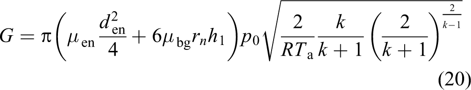
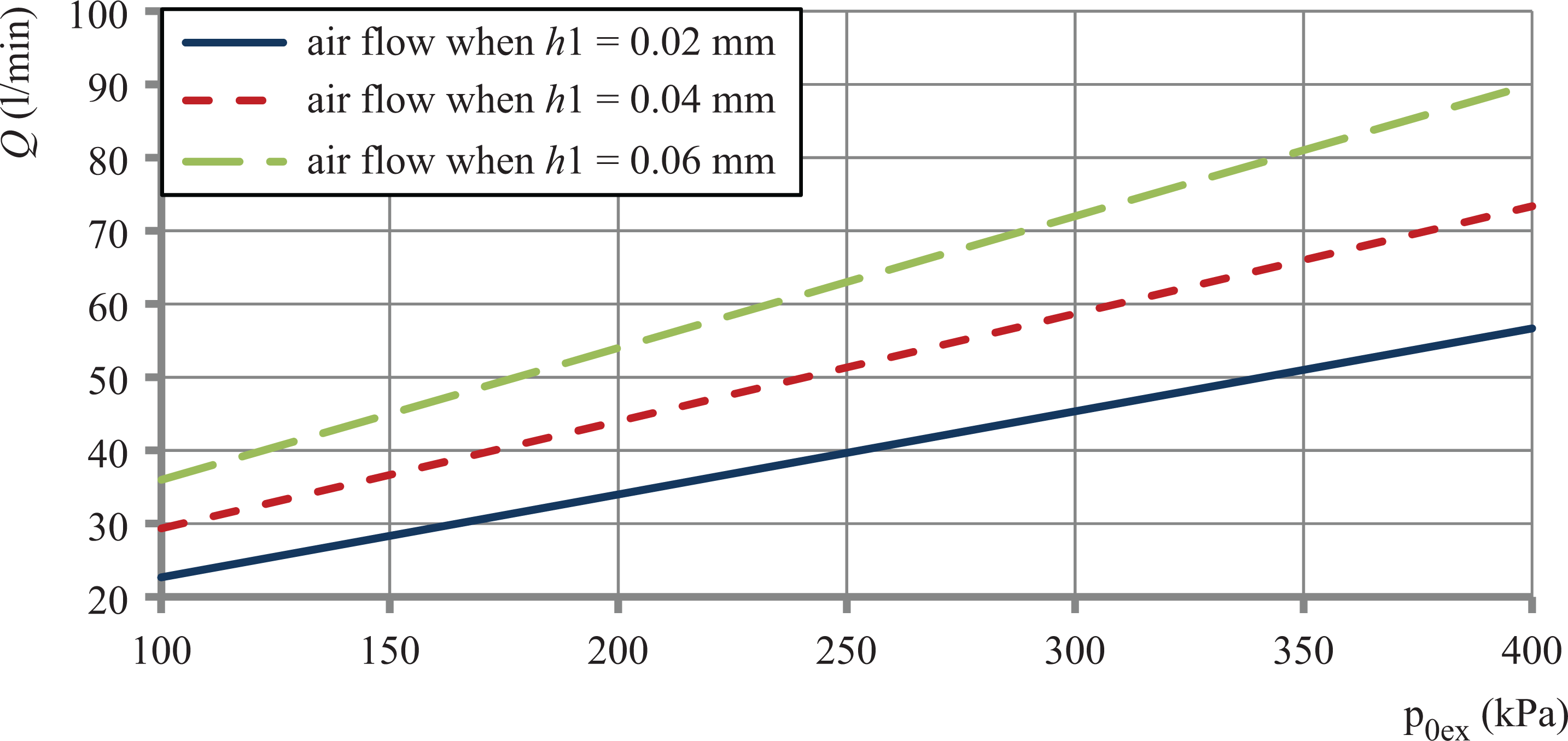
Dependence of the capacity flow of air on the pressure of the supply.
where μ bg = 0.78–0.82 is the air flow rate through the nozzle of the BGD.
The total volume of air flow is brought to normal conditions Q = G/ρ a, where ρ a = 1293 kg/m 3 is the density of air under normal conditions.
The indicator of the noise characteristics of the Bernoulli–vacuum gripping device is the level of sound that appears when the compressed air flows from the nozzle of gripper and the exhaust chamber of the ejector. At pressures of power supply of the Bernoulli–vacuum gripping device to 300 kPa, the noise does not exceed the sound level of 90 dB, which corresponds to the sanitary norms. If there is an object at the end of the Bernoulli–vacuum gripping device, the noise level is reduced. To reduce noise at the output of the ejector, silencer should be used.
The Bernoulli–vacuum gripping device is used for contactless holding of manipulation objects with a surface sensitive to damage, for example object manipulation of fragile material or objects that have different coverage.
Conclusion
Mathematical models that allow to determine the distribution of negative pressure on the surface of OM and power characteristics of Bernoulli–vacuum gripping device were proposed.
On the basis of the conducted modeling, the influence of the design parameters of the vacuum suction cup on the performance characteristics of the Bernoulli-vacuum grippers was established. The performance of characteristics of Bernoulli–vacuum gripping device was investigated.
Reasonable designs of vacuum suctions cups are presented and their parameters are explained, which will allow to increase lifting capacity of Bernoulli–vacuum grippers or to decrease compressed air flows.
Footnotes
Declaration of conflicting interests
The author(s) declared no potential conflict of interest with respect to the research, authorship and/or publication of this article.
Funding
The author(s) disclosed receipt of the following financial support for the research, authorship, and/or publication of this article: This work was supported by Slovak National Grants Req-00347-0001, VEGA 1/0065/16, APVV-16-0006 and VEGA 1/0752/17.