
Abstract
In a complex rigid–flexible coupling environment of overhead high-voltage transmission line, the manipulator robust trajectory tracking motion control of live maintenance robot is the premise of fulfilling the entire maintenance operations. In the process of manipulator’s different function reconfigurable (drainage board bolt tightening and insulator strings replacement), in response to the shortage of excessive pursuit of robust stability for robot manipulator when using H ∞ control, as it ignores the influence of structure changes caused by terminal reconfigurable on the system stability to a certain extent, the structured singular value theory–based robot robust μ synthesis control method was proposed in this article. The intrinsic relationship between structured singular value control (μ method) and H ∞ control was elaborated, a general control model of the multi-arms and multi-actions robot system was established, the multifunction terminal reconfigurable live maintenance robot with its two kinds of operations was set as a research object, and the corresponding robot μ controller was designed. In the MATLAB development environment, simulation results have shown that on the premise of maintaining the robust stability, compared to the H ∞ control method, μ control can obtain better performance robustness for the perturbation of its own structural changes in the process of different operation functions switch. Finally, the validity and engineering practicability of this method is verified by actual 220 kV live operation experiments.
Introduction
Live maintenance robot is a special electric power operation robot; it walks along a high-voltage transmission line to replace or assist artificial power maintenance, plays a very important role in the power industry, and has very broad application prospects. 1 –3 Drainage board bolt tightening and insulator strings replacement are important aspects of live maintenance operations; 4 –6 the traditional operation method always relies on a manual approach completely, and it has the disadvantages of low efficiency, high risk, as well as uncertainty of the operation state. The most typical representative electric power robot is LineScout developed by Canada Institute of Hydroelectricity in Quebec, and it has a dual function of power line inspection and maintenance. 7,8 After several years of research and development, the operation function of the robot gradually diversified, the system platform equipment technology gradually improved and matured, and simultaneously, the intelligent issues of robot operation, especially for the operation ability in harsh environment, have become one of the major bottlenecks that restrict its utility and popularization in the power sector. From the perspective of control, effective and stable control of manipulator trajectory tracking is a prerequisite for normal robot maintenance operations. In order to obtain a better control performance, the controller design must consider not only internal/external disturbance and uncertainty simultaneously but also the perturbation of the robot’s own structural change impacts on system performance. Therefore, research on the robust motion control of robot manipulator, especially in the condition of structure change caused by terminal reconfigurable, is of great theoretical value and practical significance.
In order to effectively solve the influence of disturbances, uncertainty, and structural changes on the accuracy and stability of robot manipulator motion control, scholars in related fields have proposed different methods. The trajectory tracking problem for robot manipulator is to force the output response to follow a desired trajectory as close as possible, and this problem has been solved using several efficient control methods, such as proportional–integral–derivative (PID) control, 9 computed torque control, 10 adaptive control, 11,12 and fuzzy control. 13 Indeed, in many cases, the desired trajectory of robot manipulator is repeated over a given operation time, and the usage of conventional control algorithms with such systems will result in the lack of motion robustness especially for the structure perturbation. In the aspects of robust control worldwide, Bouakrif and Zasadzinski 14 studied trajectory tracking control of perturbation robot manipulators using the iterative learning method, and the effectiveness of the proposed method was verified mainly by simulation analysis. Azimi et al. 15 proposed a H 2/H ∞ hybrid control method for robot manipulator combined with T-S fuzzy control. Xiao et al. 16 proposed robust control of a dual-arm space robot based on the backstepping method, through the selection of reasonable controller parameters; it may eliminate some nonlinear terms, so as to avoid the singular value problems when the controller design uses the traditional backstepping method. Taking into consideration the aspects of trajectory tracking control, Khaloozadeh H et al. 17 proposed a variable structure compensation controller based on bounded uncertainties and equivalent control law, which gave a real-time solution to the tracking problem. Concerning special operation robots, Vijay et al. 18 proposed a robust force control of an automatic live-line maintenance robot used in the real maintenance task of an active electric line. A robust force disturbance observer is designed using this information in an H 2 framework and implemented on two different setups; experimental results show that highly robust force tracking by the automatic live-line maintenance robot could be achieved even if the stiffness of environment and the shape of wall change. Wang et al. 19 proposed an Hamilton-Jacobi-Isaacs (HJI) inequality robust control method based on establishing an inspection robot manipulator motion model, which studied the robust control of a transmission line inspection robot under high-voltage and strong electromagnetic interference environment. Liu et al. 20 proposed robust motion control of underwater robot based on μ theory, which was performed in special operational surroundings. In summary, the most commonly used robust control method includes backstepping control, sliding mode control, Kharitonov theory, 21 H ∞ control, and structured singular value theory, especially for the latter two methods, and they have already formed a mature theoretical structure. H ∞ control can realize the robust stability of the system; however, it is difficult to obtain performance robustness on the premise of robust stability because the perturbation source is quite dispersed and easy to ignore the influence of uncertain structure. While μ control by concentrating the scattered uncertainties into a diagonal matrix, it takes the influence of system uncertainty structure into consideration, and the structured singular value μ is set as the measurement of system robustness, both the robust stability and performance robustness of the control system are all considered, so it reduces the conservativeness of the controller, and it can obtain better control effect to a certain extent especially for the specific operation environment of the special operation robot (such as high-voltage transmission line).
Based on the above analysis, as the motion state of the mechanical arm is the summation of all joint movements, in order to further improve the robustness of robot mechanical arm motion and versatility–scalability of the robot controller, this article established a dynamical model of mechanical arm motion control by combining the armature voltage equation of the joint motor, decomposing the structure of the robot control system, analyzing the dynamical model of the mechanical arm basic motions, and considering the influences of disturbances and structure change. Compared with the other robust control methods, μ robust control theory is a relatively more mature theoretical system to solving disturbances, and especially for structure change or parameter perturbation caused by robot manipulator reconfigurable at present. Therefore, this article presents a structured singular value theory–based robust control method for the manipulator of live maintenance robot, in the case of system structure perturbation when different operation functions switch in the process of manipulator reconfigurable. The aim is to make the manipulator maintain robust stability and obtain excellent performance robustness, so that a solid guarantee may be provided for robot actual maintenance operations.
Entity structure and operation principle
Entity structure
As shown in Figure 1, the live maintenance robot basically consists of mobile robot platform and terminal tools. The mobile robot platform contains a control box (part 1), double moving arms (parts 2 and 3), double mechanical arms (parts 4 and 5), double walking wheels (parts 6 and 7), clamping jaws, equipotential roller, and so on. The terminus of the moving arm is equipped with walking wheels, which help the robot walks along the transmission line and have the function of determining location. Double mechanical arms have a rotation joint, a stretch joint, and a vertical joint, additionally mechanical arm 2 has a horizontal joint. There is sufficient margin for the two manipulators to work together on the transmission line and fit within the operation space constraints. Through the different reconfigurable terminal tools, the entity structure of robot for bolt tightening and insulator strings replacement is shown in Figure 2. Through walking location and different joint actions, the robot can realize entering or exiting operation space, nut (or bolt head) alignment, bolt tightening, W pin location, insulator clamping, key actions and fulfill operation functions.
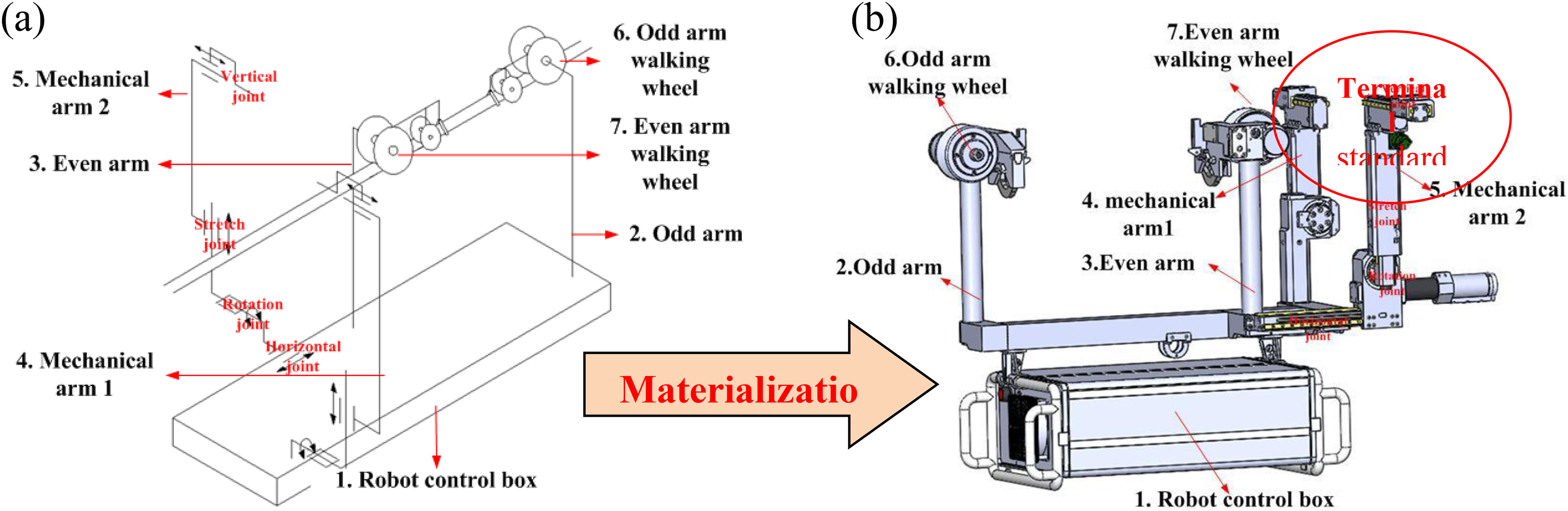
(a) Configuration and (b) Entity structure of the mobile robot platform materialization.
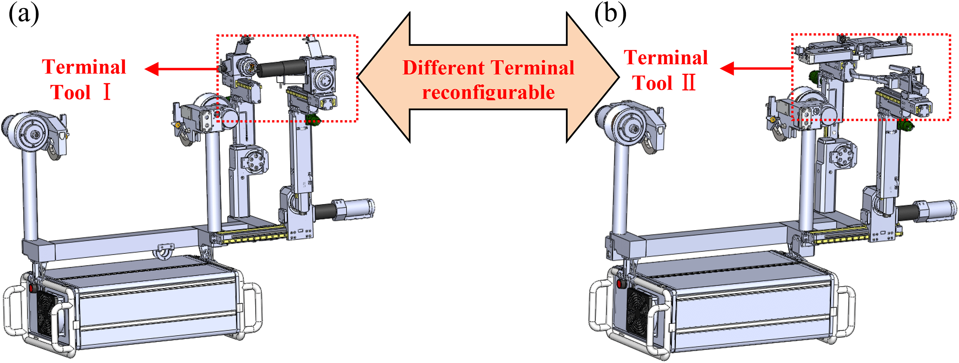
The entity structure of live maintenance robot aimed at different operations. (a) Robot aimed at bolt tightening and (b) robot aimed at insulator strings replacement.
Operation principle and motion planning
In the process of bolt tightening operation, first, the robot walks along the transmission line until its walking wheel detects and positions itself at the press- connect pipe, where upon the wheel brakes and the double arms begin to work after the double jaw clamping the transmission line (see in Figure 3(a) to (c)). Second, through the adjustment of joint manipulator 1 actions so that the manipulator 1 sleeve can be aligned accurately with the bolt head and fixed the bolt head (see in Figure 3(d)), through the adjustment of joint manipulator 2 actions so that the manipulator 2 sleeve can hold the nut, and nut tightening (or loosening) can be realized by the high-power terminal motor (see in Figure 3(e)). After the procedure has been completed, the double manipulators move away from the operation space (see in Figure 3(f)). The entire operation process can be completed by robot itself without any outside manual intervention except for the base station controlled by operator through 4G/WLAN communication. In the operation process, step (c) (Key Point 1), step (e) (Key Point 2), the motion of robot mechanical arm will be disturbed by all kinds of perturbation (high current under high-voltage strong electromagnetic environment as well as the disturbance factors such as shocks and vibrations caused by clamping movement of mechanical arm), all these situations need to consider the robust motion control of the robot.
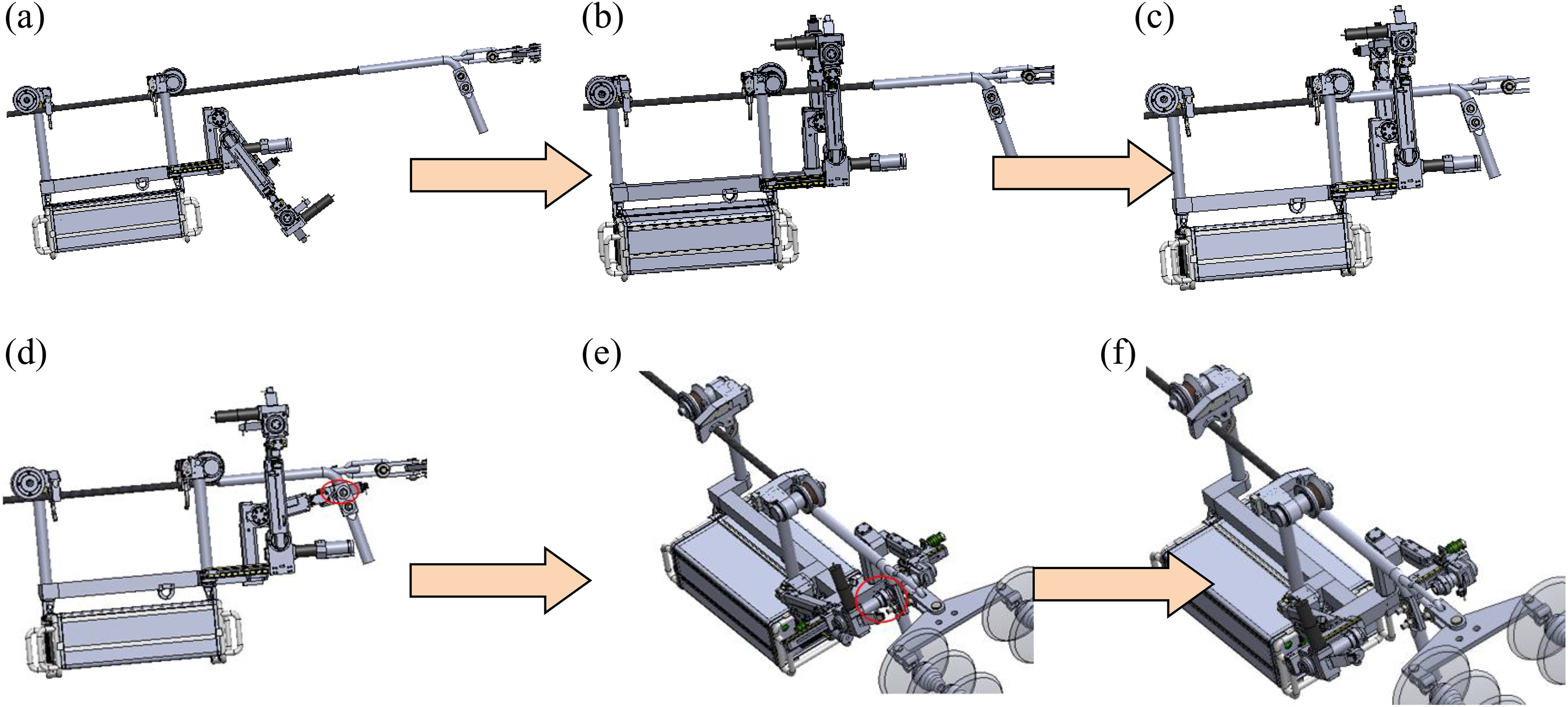
Motion planning of bolt tightening operation. (a) Online initial posture/S1, (b) walking online and rotation/S2, (c) locating the press connect-pipe/S3, (d) bolt head is fixed/S4, (e) bolt tightening/S5, and (f) exit operation space/S6.
In the process of insulator strings replacement operation, first, the robot walks along the transmission line until its walking wheel detects and positions itself at suspension clamp, where upon the wheel brakes and the double arms begin to work after double jaw clamping the transmission line (see Figure 4(a) to (c)). The key of insulator strings replacement is to roll out the joint connection component W pin through W pin pushing block (see Figure 4(d)), and then the ball head can be pushed out by horizontal movement of arm 2 so that the former insulator strings are in free state and easy to be replaced (see Figure 4(e) and (f)). The final step is to push the new insulator strings’ ball head into the bowl head notch and push-in W pin, so that the free-state insulator strings can be fixed and an entire replacement can be completed. In the operation process, step (c) (Key Point 3), step (d) (Key Point 4), step (e) (Key Point 5), and step (f) (Key Point 6), the motion of robot mechanical arm will be disturbed by all kinds of perturbation (high current under high-voltage strong electromagnetic environment as well as the disturbance factors such as shocks and vibrations caused by clamping and pushing movement of mechanical arm), all these situations need to consider the robust motion control of the robot.

Motion planning of insulator strings replacement operation. (a) Online initial posture/S1, (b) walking online and rotation/S2, (c) locating suspension clamp/S3, (d) W pin is pushed out/S4, (e) ball head pushing/S5, and (f) insulator string is in free state/S1.
Control model of mechanical arm joint motion
Robust control architecture of the robot
The architecture of robot robust motion control system is shown in Figure 5. In the process of bolt tightening and insulator strings replacement, the structure of robot control system may be divided into three layers from top to bottom, including an intelligent decision-making layer, a task coordination layer, and an action execution layer. As the top layer, the intelligence decision-making layer is the control center of the robot and is responsible for giving all control commands and monitoring the status information of the task coordination layer and action executive layer. The task coordination layer is responsible for several key operations, including robot online walking, walking location, bolt location, bolt tightening, clamping action (including bowl head clamping and insulator clamping), pushing action (including W pin pushing and ball head pushing), and so on. These operations are the embodiments of the total basic actions of all joints in the executive layer. The action executive layer is the bottom layer, which controls the basic movements of each joint, such as double arm stretch movement, rotation movement, vertical movement, horizontal movement, bolt tighten and loosen, and so on. The three layers are connected by the human–computer interaction (HCI) system through a wireless 4G network. Different complex operation functions may be realized through planning and coordination of joint basic movements in the action execution layer.

Control system structure of live maintenance robot with reconfigurable function.
The general modeling method of robot joint motion
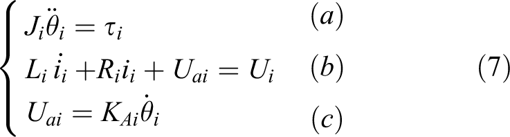
The general robot joint may be divided into two categories which are movement joint and rotation joint. Then the motion characteristics of the movement joint may be divided into two categories according to whether changes in potential energy and joint motion model may be established by the Lagrange method. Regarding the rotation joint, the joint motion model may be established by the relation equation between the rotational inertia and torque. Therefore, supposing mi is the mass of mechanical arm, the centroid displacement of the mechanical arm to which the movement joint i belongs is si , EAi is the mechanical arm kinetic energy at joint i movement, EPi is the mechanical arm potential energy at joint i movement, and τi is the summation of external forces on the mechanical arm movement at joint i. The kinetic equations of the two categories of movement joints are obtained as equations (2) and (3) by Lagrange equation (1), wherein equation (2) is the joint kinetic equation when the potential energy kept constant, and equation (3) is the joint kinetic equation when the potential energy varies


Supposing the rotation angle of the rotation joint i is θi, the mechanical arm rotational inertia is Ji , then equation (4) can be obtained by the relation equation between the rotational inertia and torque

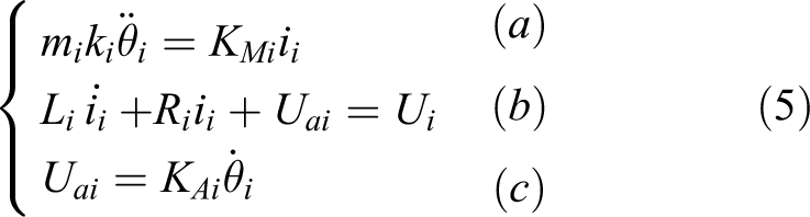
It is assumed that there is no coupling effect between the movements of the joints, then the joint motion control model with different characteristics can be obtained as equations (5) to (7), respectively, through the combination of joint armature equation

Unified dynamical model of different motions
In order to facilitate modeling and analysis of the mechanical arm motion control, supposing
Establishment of motion control mode for live maintenance robot
Motion control model construction of multi-arms multi-actions robot
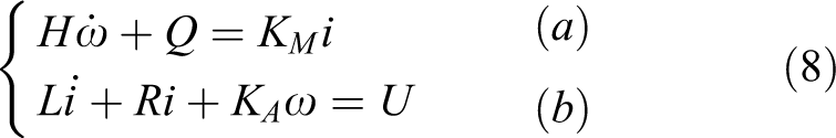
By ignoring the influences of disturbances and uncertainties on robot motion control, according to the unified expression equation (8a) of the basic movement kinetic equation, we may obtain the joint armature current and by substituting joint armature current into equation (8b), we may obtain the following equation

Because U, R, H, Q, and KM
are robot-related physical parameters and joint electrical parameters, they are all the constants; therefore, by defining

As compared with equation (10), it is more general to set u as the system input and set d as the summation of the disturbance signals and uncertainties, then we may obtain joint state equation (11) under disturbances and uncertainty factors from the steady system equation (10), wherein the function of the system input u is to suppress the influences of disturbances and uncertainty factor d on the system stability through the appropriate control variable, wherein α and β are variable parameters. They can be used to adjust the ratio between the input control variable and the disturbance or uncertainty factors, so as the control system can obtain the optimal control performance

Equation (11) can be rewritten in the form of state space as
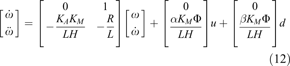
By defining the joint state variable as

Therefore, in order to simplify the system, we can define vector

Establishment of motion control model for reconfigurable terminal function robot
Regarding reconfigurable terminal function robot, double arms have stretch joint, rotation joint, vertical joint, in addition, arm 2 has a horizontal joint, supposing xi (i = 0–7) represents seven joint state variables (five movement joints and two rotation joints) of the robot double arms. Therefore, the motion control model of 7-DOF robot system can be obtained as equation (15) based on the multi-arms, multi-actions motion model, and it can be used to design the structured singular value controller

In order to solve the μ controller, system matrix should be obtained first. To simplify the calculation process, the parameters of the joint motor can be selected as simple as possible, set

Robust motion controller design of live maintenance robot
Structured singular value theory
The structure of μ synthesis problem is shown in Figure 6(a),


The block diagrams and relationship of different robust controls. (a) The structure of μ synthesis, (b) the structure of H ∞ control, and (c) the relationship between H ∞ control and μ synthesis.
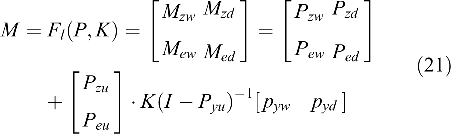
The transfer function matrix
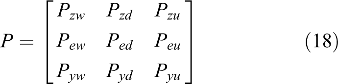


By substituting u = Ky into equations (19) and (20), through eliminating y, we may obtain system closed-loop transfer function
Therefore, the system satisfies the following three conditions so as to meet robust stability, nominal performance, and performance robustness requirements,
22
where μ(·) represents the structured singular value. (I) The sufficient and necessary condition for the system robust stability is (II) The sufficient and necessary condition for satisfying the nominal system performance is (III) The sufficient and necessary condition for the robust performance of the system is
State space for μ control method
It usually needs transfer function matrix of generalized nominal model when solving μ synthesis problem; however, it is hard to obtain the analytical model of


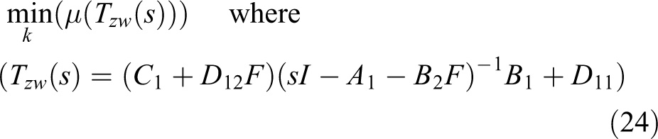
The control target of robot state feedback is to make system A 1 + B 2 F keep stability through the feedback gain matrix. If H ∞ norm is used as the performance index, it will result in the abovementioned conservatism. In order to overcome this defect, we use minimizing the system structured singular value μ of the closed-loop transfer function matrix as the control performance index, as shown in the following equation
From the above analysis, as long as the state feedback control matrix
μ Controller solving and its order reduced
The structure of robot μ control is shown in Figure 7, where w, z, u, d, y, and e are defined in the section “Structured singular value theory,” the diagonal block matrix represents structure perturbation,

The structure of robot μ control.
The small μ theorem is commonly used in the determination of the structured singular value μ stability.
23
In a structure uncertain system,

The basic idea of μ control is to use the structured singular value upper bound to solving the controller, and D-K iteration method proposed by Doyle in 1985 is commonly used in this section. The idea is to transform robust controller design into the solving of a stable controller matrix

The alternate optimization method of scale transformation matrix

Flow chart of D-K iteration method.
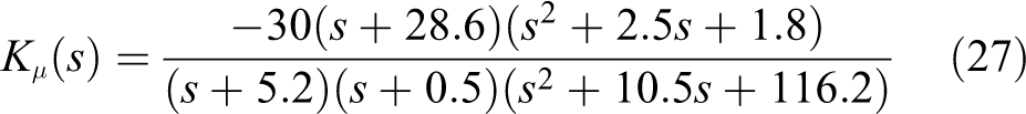
In order to facilitate the hardware implementation, μ controller should be order-reduced processing according to the Hankel-norm method, 24 and the controller transfer function is as follows
Simulation and field experiment
Simulation
The D-K iteration process can be solved using the μ toolbox provided by MATLAB. We can enter the μ toolbox by entering

The implement of D-K iteration algorithm. (a) μ parameter setting interface and (b) D-K iteration numbers and system μ value.
To further verify the performance robustness and superiority of the μ-controller designed in this article, the simulation experiments are divided into two parts. Firstly, the system stability and response speed simulation experiment are performed when robot reconfigurable different terminal tool uses μ controller and H ∞ controller, respectively, under the condition of different structural perturbations, where Figure 10(a) is the output curve of μ control with the system structure perturbation of 15%, 10%, 5%, and the nominal model, Figure 10(b) to (d) is the performance comparison of μ controller and H ∞ controller control with the structure perturbation of 15%, 10%, and 5%, respectively. The system performance under different structural perturbations and different control methods is shown in Table 1.

The simulation experiment comparison between H ∞ control and μ control. (a) μ Control with different structural perturbations, (b) μ and H ∞ control with 15% structure perturbation, (c) μ and H ∞ control with 10% structure perturbation, and (d) μ and H ∞ control with 5% structure perturbation.
The performance comparison between μ and H ∞ control.

From the simulation results and performance comparison, we can get the conclusion that under different perturbation conditions, the μ control system can converge to stable state at different speeds. The greater the perturbation, the slower the convergence speed and the greater overshoot, but ultimately the system can guarantee convergence, which shows that the μ control can keep the robot system robust stability. In addition, under the same perturbation, the peak of the μ control curve is smaller than that of the H ∞ control obviously and the overshoot of μ control curve is smaller than that of H ∞ control. The above analysis shows that the μ control is much more better than H ∞ control in ensuring the robust stability of the system, and the robustness of the robot manipulator with fast response speed and better stability can also be obtained.
Secondly, in order to verify the tracking performance of the system and superiority of the μ controller designed in this article, the simulation experiments of manipulator trajectory tracking are performed using μ controller and H ∞ controller, respectively, and the disturbance signal is given to the system simultaneously. The simulation results are shown in Figure 11, where Figure 11(a) is tracking of square wave using μ method, Figure 11(b) is its corresponding error curve, Figure 11(c) is tracking of typical trigonometric function signals using μ method and H ∞ control, respectively, and Figure 11(d) is tracking of irregular trigonometric signals with different frequencies using μ method and H ∞ control, respectively.
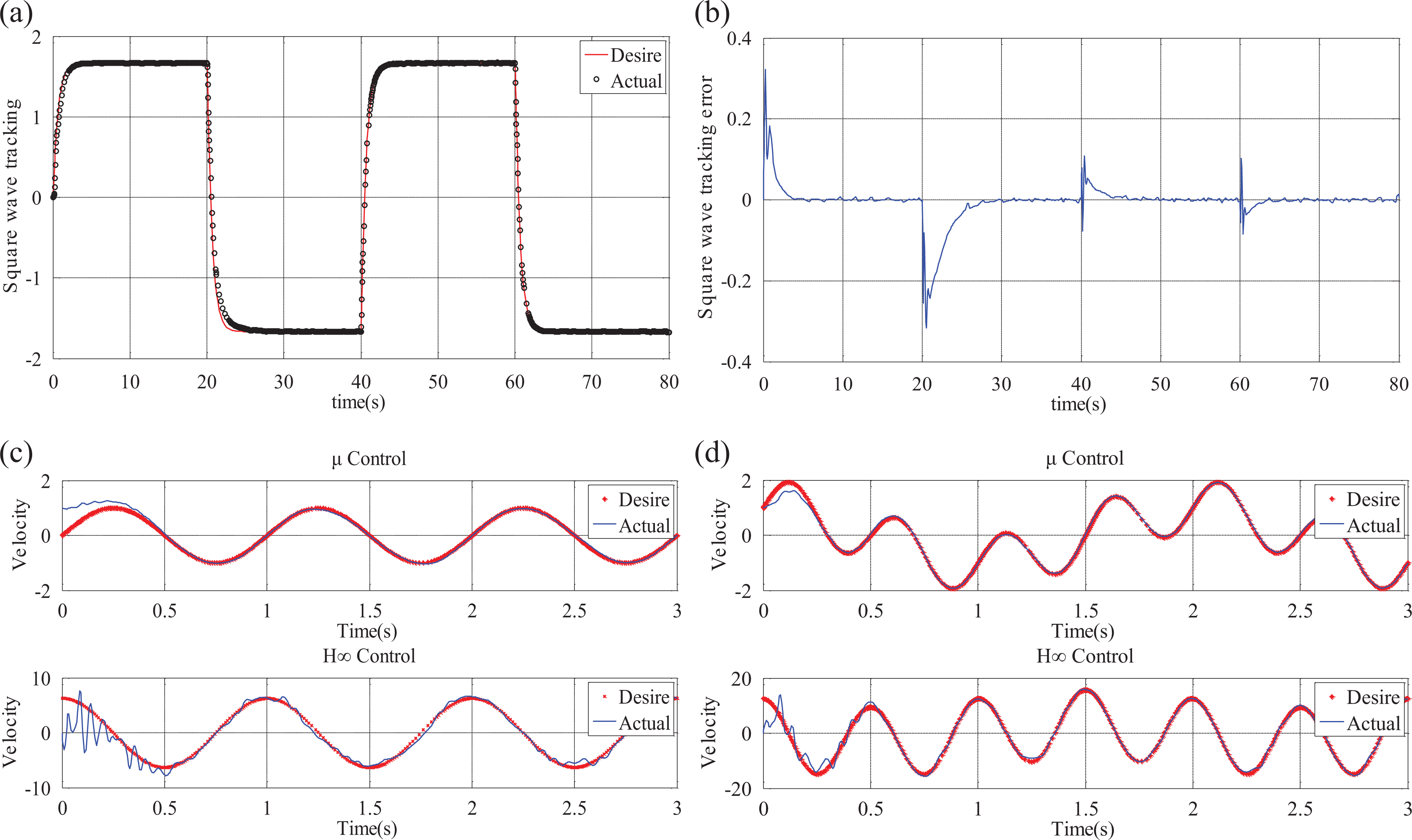
Simulation experiment of manipulator trajectory tracking. (a) Tracking of square wave signals, (b) Tracking error of square wave signals, (c) Tracking of typical trigonometric signals, and (d) Tracking of irregular trigonometric signals.
Combining the trajectory tracking control simulation results of the three sets of experiments in Figure 11, it becomes apparent that μ control can obtain excellent robust performance in square wave tracking, and smaller tracking error occurs only when switching between high and low levels. The two kinds of robust control methods may suppress the influences of strong impact, periodic disturbance signal (square and triangular wave signal) and its superimposed signal on the trajectory tracking performance, and realize the trajectory tracking of complex curves such as typical trigonometric function and trigonometric superposition of different frequencies. However, the tracking accuracy and the stability under μ control is much more better compared to H ∞ control; therefore, the μ control method proposed in this article is effective and may meet the design requirements such as fast response speed, high tracking accuracy, and sound stability in control system design. The proposed μ control method is much more suitable for dealing with structure perturbation problems compared to H ∞ control.
Field experiment
In order to further verify the engineering practicability of the μ control method, the drainage board bolt tightening and insulator strings replacement operation of reconfigurable terminal function robot were carried out (see Figure 12, the different types of disturbances are marked on the corresponding figure) on an actual 220 kV high-voltage transmission line under the administration of the Hunan Electric Power Company Live Working Center in Hunan Province, China, the tower number is #006, the type of the tower is ZB1-24, and the type of the wire is LGJ-400/50. To realize dynamic monitoring for the robust stability of the robot manipulator motion during the operation, the actual velocities of the four kinds of joint motor may be measured in real time by an encoder installed on the joint motor of mechanical arm, wherein the maximum rotation velocity of the joint motor is 1 Kr/min (1000 rotations per minute). To secure the safety of the operation, the rotation velocity is normally maintained within 0.8 Kr/min. As the rotation joint will overcome gravity during the motion process and the vertical movement joint only moves at the end of the mechanical arm, the desired velocity of the rotation joint requires that the maximum velocity vertical shift joint requires the minimum velocity, the stretch joint and horizontal joint require a medium velocity, and the ideal velocity for rotation joint, stretch joint, horizontal joint, and vertical shift joint may be set as 0.8, 0.68, 0.65, and 0.6 K r/min, respectively. In the process of two operation functions switch, the actual velocity tracking curve for the joint motor of robot mechanical arm in field operation experiments under μ control and H ∞ control is shown in Figure 13.

Field operation experiment. (I) Drainage broad bolt tightening: (a) Location press-connection pipe, (b) double arm initial posture, (c) double arm actual posture, (d) manipulator 1 dock with bolt head, (e) manipulator 2 capture nut, and (f) bolt tightening. (II) Insulator strings replacement: (a) Double manipulator initial posture, (b) double manipulator operation posture, (c) suspension clamps location, (d) bowl head holder and W pin pushing, (e) insulator holder, and (f) ball head pushing.
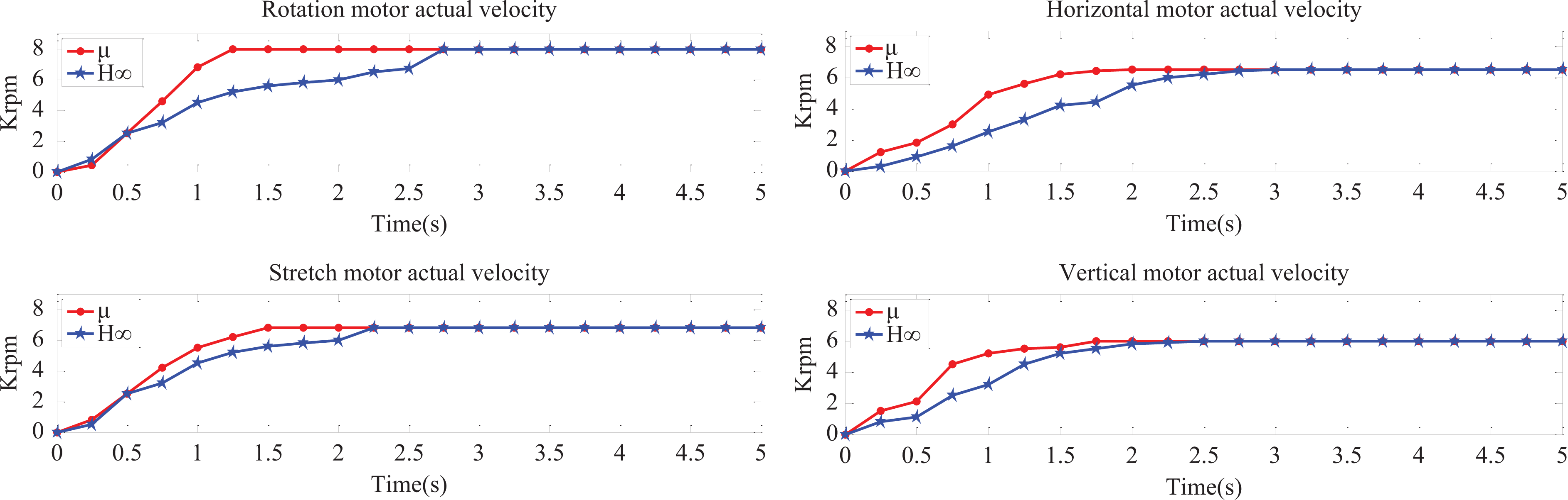
Actual velocity tracking of robot joint. (a) Actual velocity tracking of rotation and stretch joint and (b) actual velocity tracking of horizontal and vertical joint.
According to Figure 13, it may be shown that the actual velocity of the four kinds of joint motors (rotation, stretch, horizontal, and vertical) converges to the given ideal velocity at t = 1.25, 1.5, 2, and 1.75 s, respectively, under μ control, and after that a sound tracking performance may be maintained. While the actual velocity of the four joint motors converges to the given ideal velocity at t = 2.75, 2.25, 3, and 2.5 s, respectively, under H ∞ control, and after that a sound tracking performance may be maintained. Therefore, we may conclude that compared to H ∞ control, on the premise of maintaining stability, the joint motor of mechanical arm may achieve faster convergence speed under the μ control.
In order to make a contrast among μ control, H ∞ control, and conventional PID control, operation experiments were carried out three times using three different control methods. The robustness of robot mechanical arm motion was tested in macro level, in order to dynamically monitor the macro robust stability during insulator replacement process in which different motions were performed. The angle ranges measured by inclination sensor and carried out by robot itself are recorded in Table 2 when using three different control methods. And its corresponding macro stability simulation experiment of robot arm motion with three different control methods is shown in Figure 14.
Inclination sensor value range of mechanical arm 2 different action (line slope = 10°).

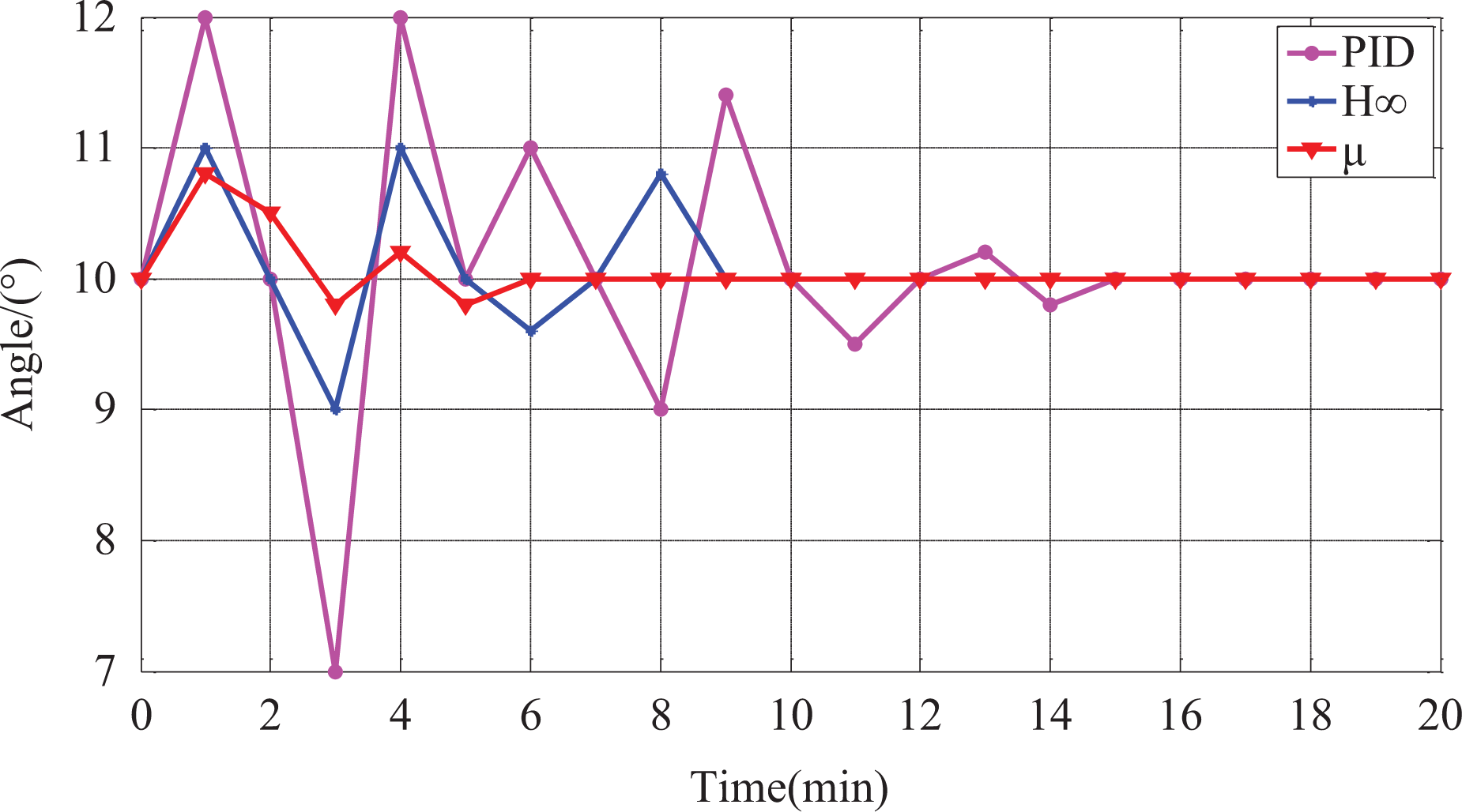
Robust stability simulation of manipulator motion.
Figure 14 shows that the measured values of inclination sensor using PID control, H ∞ control, and μ control are maintained at 10° after 15, 10, and 6 min, respectively, indicating that the time consumed for finishing task using PID control is about 15 min (not including on-line and off-line time), and the time consumed for finishing task using H ∞ control and μ control is about 9 and 6 min, respectively (not including online and off-line time). Without robust control, there are significant errors of trajectory tracking and location of manipulator due to the influences of disturbances and uncertainty factors; therefore, it needs more artificial intervention and adjustment for the control of mechanical arm, so that more time will be consumed. However, after applied with robust control, the robustness of mechanical arm increases, and trajectory tracking and location are more accurate, which decreases artificial intervention, shorten operation time by about one-third, especially for μ control, shorten operation time by about two-third, and greatly improve the operation efficiency of robot. In addition, according to the inclination angle range of different movements of mechanical arm using three different control methods shown in Table 2 and Figure 14, it can be observed that the inclination angle of different movements of mechanical arm measured using μ control is uniformly smaller than that measured using H ∞ control; therefore, it can be concluded that the mechanical arm moves more stably using μ control compared to H ∞ control and PID control.
Therefore, it can be concluded from the field operation experiment that through multi-function operation terminal reconfigurable and the joint movement of robot manipulator, the double arms and the double manipulators from the initial posture to the operation posture, insulator strings clamp positioning, bolt positioning and exit or enter operation space, key states, robot manipulator shows a sound performance robustness under the structured singular value control in the process of operation terminal reconfigurable, there was no overshoot of joint movement, all joints run smoothly, continuous, and stable. Therefore, the proposed μ method has a strong engineering practicability no matter different manipulators reconfigurable, so it further improves the operation efficiency and reflects the robot operation intelligence to some extent.
Conclusion
An experimental prototype of a live maintenance robot with reconfigurable terminal function for high-voltage transmission line has been developed, which can fulfill two kinds of operation functions, namely drainage board bolt tightening and insulator strings replacement. In this way, the designed robot greatly improves operation efficiency and deals with the safety problem of operation in a high-altitude and high-voltage environment.
Through layering robot control architecture, a dynamic model of mechanical arm basic motion was established by the Lagrange method combined with an armature voltage equation of the joint motor, and the unified dynamic model of mechanical arm different motion was obtained.
A general multi-joints manipulator motion control model of a multi-arms multi-actions robot is established based on the joint unified dynamic model, the motion control model of robot with reconfigurable terminal function is obtained based on the proposed model, and the robot robust μ control model is established based on the joint motion control model.
Through the comparison of simulation experiment using H ∞ and μ control methods, it is verified that the μ control achieves better performance robustness under the premise of ensuring the motion stability of the mechanical arm especially for structure perturbation. A field experiment has further confirmed the engineering practicability of the proposed μ control method.
Footnotes
Acknowledgements
The authors would like to gratefully acknowledge the State grid Hunan electric power company of China, Guangdong Robot Special Project, Foshan Technical Innovation Team Project and South Wisdom Valley Innovative Research Team Program. The authors also wish to thank anonymous reviewers, each of whom provided comments that directed important improvements in the manuscript.
Declaration of conflicting interests
The author(s) declared no potential conflicts of interest with respect to the research, authorship, and/or publication of this article.
Funding
The author(s) disclosed receipt of the following financial support for the research, authorship, and/or publication of this article: This work was supported by State Grid Hunan Electric Power Company of China (5216A01400B1), Guangdong Robot Special Project (2015B090922007), Foshan Technical Innovation Team Project (2015IT100143), and South Wisdom Valley Innovative Research Team Program (2015CXTD01).