
Abstract
Nuts and bolts are common components in assembly lines. Their position and pose estimation is a vital step for automatic assembling. Although many approaches using a monocular camera have been proposed, few works consider a monocular camera’s active movements for improving estimation accuracy. This article presents an active movement strategy for a monocular eye-in-hand camera for high position and pose estimation accuracy of a spatial circle. Extensive experiments are conducted to validate the effectiveness of the proposed method for position and pose estimation of circles printed on paper, real circular flat washers, and nuts.
Introduction
Anthropomorphic dual arm robots that can execute complex bimanual operations to replace or work with human workers in unstructured environments have been attracting more and more attention. 1 It is anticipated that robots will perform human-like tasks in both domestic and industrial settings. Accurately localizing objects is of great importance for efficiently accomplishing a grasping task, which is one of the common applications of robots. 2 One example is a robotic automotive tire assembly scenario involving various sizes of nuts and bolts. An arm with a gripper is assigned the task of picking up the right nuts or bolts whose pose and position may be arbitrary in the workspace, screwing bolts into the holes of hubs, and screwing nuts to the bolts.
The position and pose of an object in Cartesian space can be directly estimated with images. Features extracted from images are used to acquire the relative position and pose estimation of an object with respect to the camera image frame usually with the help of a geometric three-dimensional (3-D) model of the object. 3 Using the correspondence between the geometric features of objects and their projections in the image plane, such as circular features, 4 triplet of image lines, 5 and five points, 6 some closed-form analytical solutions of 3-D position and pose estimation have been presented. In order to deal with challenges due to changes in illumination, rotation, scale, and viewpoint, several invariant feature descriptors, such as scale invariant feature transform (SIFT), 7 speeded up robust features, 8 and Affine-SIFT 9 are being used to find the correspondence between an input image and a data set of images whose features alone with their 3-D coordinates are stored off-line or built in advance.
Considering the requirements of efficiency and robustness of pose estimation, recursive methods which rely on temporal-filtering, such as extended Kalman filter, have been proposed. 10 These methods need an object’s geometric model and assume zero-mean Gaussian noise. Although an object’s geometric model can be reconstructed simultaneously with pose estimation, 11 the reconstruction leads to high computation complexity. Statistics of the measurement and dynamic noise need to be known in advance and must remain constant. Poor measurement and dynamic models or poor noise estimates degrade the estimation performance. Iterative adaptive Extended Kalman Filter (EKF) is proposed for dealing with these varying statistics. 12 Several filter parameters need to be tuned in order to make the filter work. The sampling rate for the filter must be high enough to guarantee accuracy performance, otherwise, the system performance would be degraded.
Binocular vision systems are used to estimate 3-D position and pose without requiring 3-D models stored or built in advance. 13 Multicamera sensor fusion techniques are employed for more accurate and enhanced robust pose estimation. 14 An improved hybrid filter is proposed to estimate the object pose by fusing data from multiple cameras. Red Green Blue Depth (RGB_D) cameras have also been used for object pose estimation. By combining multimodal cues, such as two-dimensional local features SIFT, 3-D local features, and 3-D semi-global features, which are extracted in parallel and independently based on color, shape, and size cues, an object’s 6-degrees of freedom (DOF) pose hypothesis is generated. 15 A sensor-fusing system, which consists of a camera, a line laser, and an inertial measurement unit, is used to estimate the spatial circle and trunk parameters. 16 Measurements from a monocular vision system are fused with inertial/magnetic measurements for pose estimation. 17 However, due to the limited workspace of dual arm robots, the monocular eye-in-hand system is preferred, especially for small nuts and bolts. This system rigidly attaches a monocular camera next to the end effector.
Circular shape is the most common geometric feature that has been addressed for 3-D position and 3-D pose estimation because many manufactured objects have circular holes or circular surface contours. There exists two possible pose solutions for a single circle while reconstructing with a single perspective image. 18 The duality problem can be solved with external geometric constraints, such as vertices of a convex hull, 19 known radius, and detected center, 20 two concentric circles, 21 two coplanar circles, 22 circles with same rotation center axis, 23 and circles with different rotation center axis. 24 Six-dimensional (6-D) position and pose estimation of a nut can be obtained by using one image from the monocular eye-in-hand system with a prior knowledge of the nut’s geometry. However, there are many kinds of nuts and bolts in automotive assembly lines. Moreover, they lack obvious color and texture. In this situation, it is impossible to estimate the posture of nuts with only one image. Without a prior knowledge of a spatial circle, its 6-D position and pose can be estimated with two images from two different perspectives. Aiming at the application of autonomous underwater vehicle (AUV) docking in a circular-shaped docking station, the fact that the eccentricity of an ellipse monotonically decreases with decreasing view angle is exploited for pose estimation of the circular docking station. 25 The eccentricity of the ellipse from progressively captured images is computed and the AUV moves in the direction such that eccentricity →0 and hence ellipses tends to a circle. With these images, the correct orientation solution can be acquired. Their research has not concerned the effect of the perspectives on estimation errors of 6-D position and pose nor the design of the monocular eye-in-hand system’s moving trajectory to improve the estimation accuracy.
This artilce focuses on active 6-D position-pose estimation with a monocular eye-in-hand system for nuts and bolts without a prior knowledge of size. The monocular vision system is moved to obtain two images from two different perspectives. The two images are used for 6-DOF posture estimations of nuts. Then, the influence of the two perspectives on position-pose estimation performance is analyzed and the movement trajectory of the monocular eye-in-hand system can be designed for more accurate position-pose estimation.
This article is organized as follows. The section entitled, “6-DOF position and pose estimation of a spatial circle with monocular eye-in-hand system” describes the process of 6-D position-pose estimation with two images taken by a monocular eye-in-hand system from two different perspectives. The section, “Influence of monocular eye-in-hand system’s perspectives on 6-D position-pose estimation performance of a spatial circle” analyzes the influence of the two perspectives on position-pose estimation performance. Based on this analysis, the section, “Active movement strategy for 6-D position-pose estimation of a spatial circle” presents the active movement strategy of a monocular eye-in-hand for improving the estimation accuracy. The verification of the proposed method is provided in the section “Experiments and discussions”. The last section summarizes this article.
6-DOF position and pose estimation of spatial circle with monocular eye-in-hand system
As shown in Figure 1, a robotic arm is mounted with a camera and an end-effector. Without requiring any prior knowledge of a nut, its 6-DOF position and pose can be estimated with two images taken by the monocular eye-in-hand system from two views.

Coordinates and nut’s position and pose.
Hand-eye calibration
The position/pose relationship between the robot’s end effector coordinate (
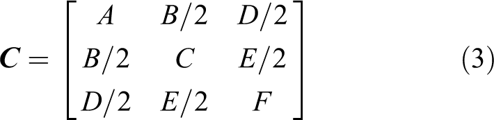
The projection matrix of the camera that performs the projection between the world coordinate space ℜ
3 and the image plane ℜ
2 is a 3 × 4 matrix

where,
The projection matrix

where,
Ellipse detection
Assume that one image has been taken by the calibrated monocular eye-in-hand system. A fast ellipse detection method is used to detect the ellipse in the image.
27
The detected ellipse’s φ center coordinates
where
Matching ellipses in two images
Given the projection matrix

where
Quan proved that reconstructing a spatial circle from two perspectives is equivalent to finding a value of λ such that the λ-matrix

Equation (5) is used for matching the two ellipses in the two images. In practice, a small-value threshold is used to combat image processing noise.
Calculating the spatial circle’s center and normal vector
The spatial circle’s center cannot be directly reconstructed with the geometric centers of the two ellipses by stereo vision methods. This is because distortion resulting from perspective projection transformation renders the projection of the spatial circle in the image different from the ellipse’s geometric center. 29
By joining the two ellipses φ 1, φ 2 in the two corresponding image planes to the camera’s optical centers at the two positions respectively, the two elliptic cones π 1 and π 2 are built. In each of the elliptic cones, two circles which have the same projection profile can be obtained. The normal vector and the center projection of each circle can be calculated. By matching the circles in the two cones, the circle which is parallel to the spatial circle can be determined in each of the cones. The projection of the spatial circles center can be computed with the centers of the two parallel circles. 30 The computational procedure is given as follows.
Step 1: Obtain the ellipse (τ 1) whose major axis parallel to the spatial circle in π
As shown in Figure 2, an elliptic cone π is built with the optic center Oc
and the projection ellipse φ in one image. The center of φ is Oe
. Initialize

Position relationship between the elliptic cone and the image plane.
Step 2: Obtain two rotation circles
C
1 and
C
2
As the ellipse τ
1 rotates ±γ around its major axis, two circles,

Step 3: Compute the rotation circles’ normal vectors and their projection centers
The normal vectors of the two circles are

The two circles’ centers are
Step 4: Obtain the two parallel circles
Similarly,
Step 5: Compute the spatial circle’s normal vector
n
and its center coordinate
X
c
The spatial circle’s normal vector
Calculating the spatial circle’ s radius
After computing the spatial circle’s center

where
As shown the proof in the first section of Appendix 1, the projection of a spatial circle of 3-D Cartesian coordinates (
Influence of monocular eye-in-hand system’s perspectives on 6-D position-pose estimation performance of a spatial circle
With two different images taken by the monocular eye-in-hand system from two different views, the estimation performance for the spatial circle’s center coordinate
Influence factor for computation error of the spatial circle’s normal vector
The spatial circle’s normal vector is
Set

The measuring error

As shown in the second section of Appendix 1, it can be easily proved that
Since the normal vector of the spatial circle is
Influence factor for computation error of the spatial circle’s radius
Due to image processing errors, the projection of 3-D point

Influence of α (the angle between the optic axis and spatial circle’s plane) on computation error of radius.
Assume that the distance
The computation error is

As shown in the third section of Appendix 1, it can be easily proved that
Influence factor for computation error of the spatial circle’ s center coordinates
The spatial circle’s center is computed by using the linear triangulation stereo vision method. 31 As shown in Figure 4, the shaded uncertainty region depends on the angle of the two rays that connect the spatial circle’s center with the camera’s optical center at two positions respectively.

Uncertainty of reconstruction with the linear triangulation stereo vision method. 31
The angle between the two rays should be large enough to decrease the computation error of the spatial circle’s center coordinates.
Active movement strategy for 6-D position-pose estimation of a spatial circle
From the analysis in the above section, the following three conditions should be met for better 6-D position and pose estimation of a spatial circle with two images through the linear triangulation stereo vision method.
The three conditions are: The projection ellipses should locate in the images’ centers.
If condition 2 and condition 3 are satisfied, then the angle of the two rays that connect the spatial circle’s center with the camera’s optical center at two different positions are large enough for decreasing the spatial circle’s center coordinate computation error.
In order to satisfy the above three conditions, we design the following active movement strategy of a monocular eye-in-hand system.
At first, assume that one ellipse is detected with the monocular eye-in-hand system, as shown in Figure 5. Control the monocular eye-in-hand system to move until that the projection ellipse is in the center of the image and the major axis of the projection ellipse is parallel to the

Active movement strategy.
Step A: Move eye-in-hand system to Location 1
Compute
If
If
Step B: Move eye-in-hand system to Location 2 and Location 3
Compute the spatial circle’s center
From Location 1, make (
After the above movements, the optic center of the camera at Location 1, Location 2, Location 3, and the spatial circle’s center are in a single plane. The angle between the ray that connects the optic center of the camera at Location 2 with the spatial circle’s center and the ray that connects the optic center of the camera at Location 3 with the spatial circle’s center is
With the above active movement strategy, the three conditions can be met. The projection ellipses are always in the center of the images taken at Location 1, Location 2, and Location 3.
Moreover, the angle between the ray that connects the optic center of the camera at Location 2 with the spatial circle’s center and the ray that connects the optic center of the camera at Location 3 with the spatial circle’s center is large enough for decreasing the spatial circle’s center coordinates computation error.
Step C: Compute the spatial circle’ s center coordinates, normal vector, and radius
With the images taken at Location 1, Location 2, and Location 3, the spatial circle’s center coordinates
1. Spatial circle’s center coordinates
The spatial circle’s center coordinates
2. Spatial circle’s normal vector
The projection ellipse with the smaller ratio of semi-minor axis to semi-major axis in the images taken at Location 2 or Location 3 is chosen for decreasing normal vector computation error. 3. Spatial circle’s radius r.
Due to the ratio of the semi-minor axis of length to the semi-major axis of length of the projection ellipse of the image taken at Location 1 is near to 1, the projection ellipse of the image taken at Location 1 is used for computing the spatial circle’s radius r.
Experiments and discussions
Extensive experiments were conducted to validate our proposed method. A Logitech C910 camera is attached to the end of a Universal Robot UR5. Three cases are considered: one circle printed on A4 paper, one circle flat washer, and one nut. In order to avoid computation error caused by coordinate transformation, a calibration board is used as the reference coordinates and placed beside the printed circle, the circle flat washer, and the nut, as shown in Figure 6. The radius of the printed circle is 40.5 mm. The radius of the inner and outer circles of the circle flat washer are 40 mm and 16.5 mm, respectively. The radius of the inner circle of the nut is 16 mm. The calibration board is a 6 × 9 checkerboard with each tile having a side length of 15 mm. For software, we use Visual Studio 2010 and Matlab 2010b. The computer is Intel (R) Core (TM) i5-4590 CPU, 3.30 GHz, 4.00 GB RAM.

Experiment scenes.
Experiments of influence of monocular eye-in-hand system’s perspective on estimation performance of the printed circle’s normal vector, center coordinates, and radius
The printed circle’s normal vector
As shown in Figure 8, the camera moves around the printed circle. Initially, the angle between the optical axis of the camera at P
0 and the plane of the printed circle is almost 90°. Then, the angle gradually decreases until
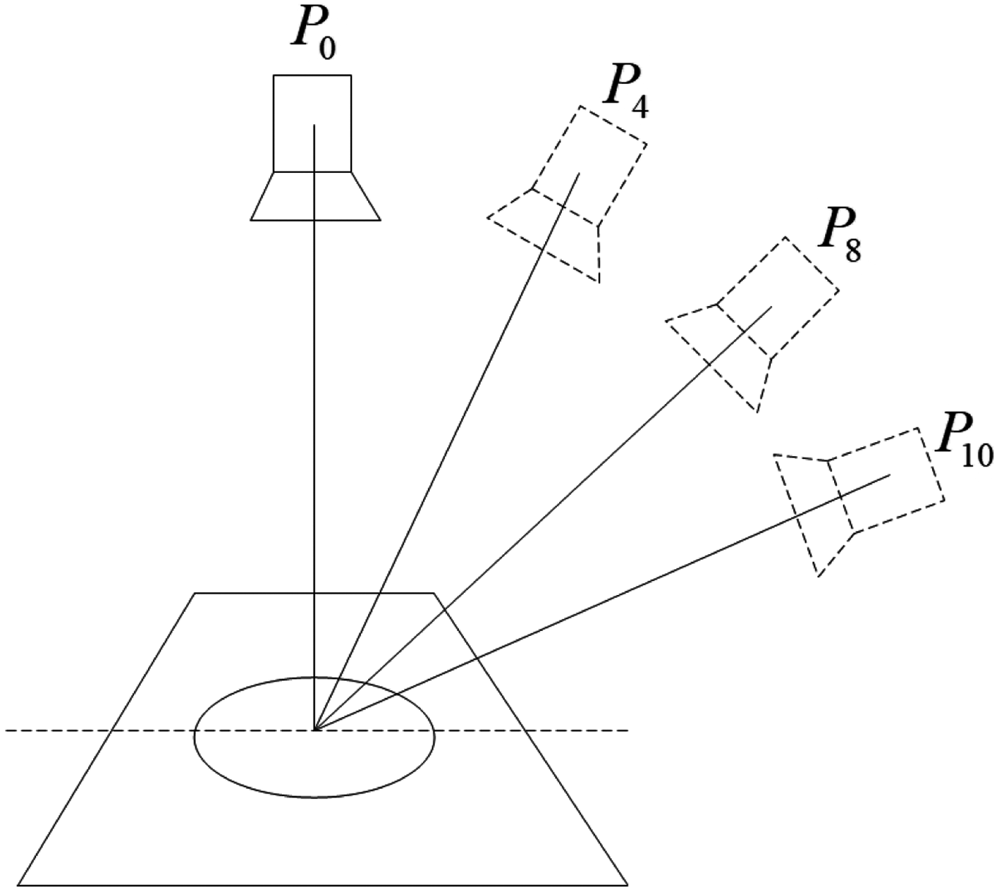
Position of the monocular eye-in-hand system and printed circle.
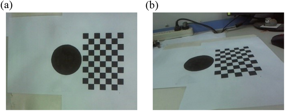
Images of printed circle. (a) P 0 and (b) P 10.
At first, the projection ellipses of the images taken at P
1,
The average computation errors of the printed circle’s center coordinates
Computation errors of the printed circle’s center coordinates

The values of boldface are the best.
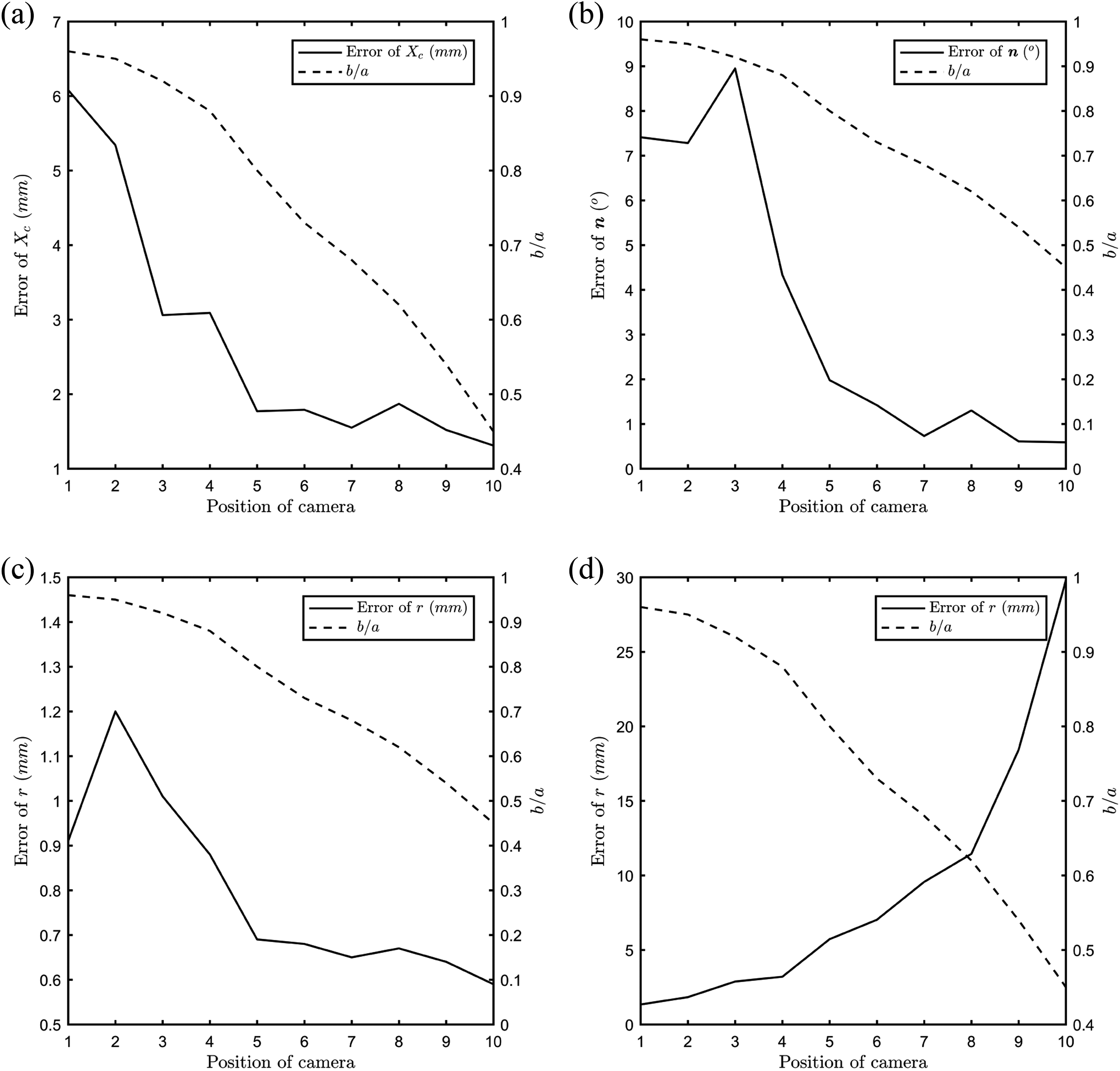
Influence of
Line 2 of Table 1 and Figure 9(a) show that the computation error of the printed circle’s center coordinates
From Line 3 of Table 1 and Figure 9(b), it can be seen that the computation error of normal vector
With the computed normal vector
From the above experimental results, we can see that the printed circle’s center coordinates
The experimental results validate the analysis of the influence of monocular eye-in-hand system’s perspective on a spatial circle’s 6-D position-pose estimation performance.
Comparison experiments for 6-D position-pose estimation of the spatial circle with different movement strategies
In order to validate the effectiveness of the active movement strategy, the comparison experiments have been done for 6-D position-pose estimation of one circle flat washer and one nut. Images are taken by the monocular eye-in-hand system with the proposed active movement strategy, the movement strategy in the study by Ghosh et al., 25 and the random movement strategy, respectively.
With the proposed active movement strategy, three images are taken at Location 1, Location 2, and Location 3 in each experiment, as shown in Figure 10. The circular flat washer’s normal vector
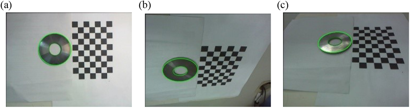
Images of circular flat washer with active movement. The green ellipses are detected. (a) Location 1, (b) Location 2, and (c) Location 3.
Circular flat washer
The circular flat washer has one inner circle and one outer circle, as shown in Figure 6(b). Twenty experiments have been done with the proposed active movement strategy, the random movement strategy, and the movement strategy in the study by Ghosh et al., 25 respectively. Three images taken at Location 1, Location 2, and Location 3 are shown in Figure 10. The average estimation error of the pose and position of the circular flat washer is shown in Table 2.
Estimation error of 6-D position and pose of the circular flat washer.

ri
: radius of inner circle; ro
: radius of outer circle;
The average estimation error of the pose and position of the circular flat washer is shown in Table 2. The estimation error with the active movement strategy is much smaller than that with random camera movement and the movement strategy in the study by Ghosh et al. 25 Furthermore, the estimation error of the inner circle’s radius is larger than that of the outer circle. The reason is that the edge shadow has an influence on the inner circle’s projection ellipse in the image.
Nut
The nut is shown in Figure 6(c). Twenty experiments have been done with the proposed active movement strategy, the random movement strategy, and the movement strategy in the the study by Ghosh et al., 25 respectively. Three images taken at Location 1, Location 2, and Location 3 are shown in Figure 11. The average estimation error of the pose and position of the nut is shown in Table 3. The estimation error with the active movement strategy is smaller than that of the random movement and the movement strategy. 25

Images of nut with active movement. The green ellipses are detected. (a) Location 1, (b) Location 2, and (c) Location 3.
Estimation error of 6-D position and pose of the nut.

δr : relative error of r. The values of boldface are the best.
The movement of the monocular eye-in-hand system is planned in order to obtain the images from special perspectives. With the images from special perspectives, 6-D position-pose estimation of the nut can be improved. However, its cost is runtime for active movements, as shown in Table 4. It can be seen that the time for active movement is a large proportion of the total runtime. It is the disadvantage of the proposed method.
Runtime for 6-D position-pose estimation of the nut.
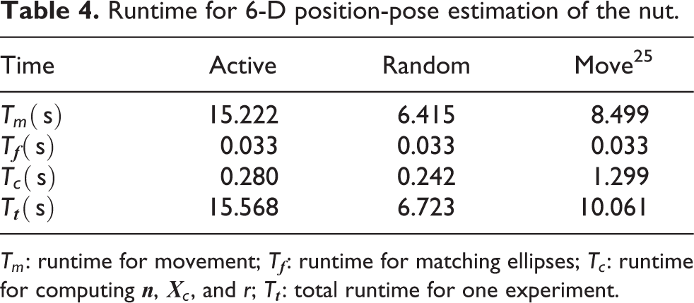
Tm
: runtime for movement;
Conclusions
A method is proposed to plan the movement of a monocular eye-in-hand system for improving the position and pose estimation accuracy of a spatial circle. The analysis of the influence of the monocular eye-in-hand system’s perspective on the position and pose estimation accuracy of a spatial circle is given. Based on the analysis, the active movement strategy of the monocular eye-in-hand system is proposed for more accurate position and pose estimation of a spatial circle. Extensive experiments have been done to demonstrate the effectiveness of the proposed method for position and pose estimation of one printed circle, one circular flat washer, and one nut. The experimental results validate that 6-D position and pose estimation error with active movement strategy is smaller than that of random movement and other movement strategy. It is also needed to be pointed out that the improvement of estimation performance is at the expense of the time for movement.
Footnotes
Declaration of conflicting interests
The author(s) declared no potential conflicts of interest with respect to the research, authorship, and/or publication of this article.
Funding
The author(s) disclosed receipt of the following financial support for the research, authorship, and/or publication of this article: The study has been funded by the National High-tech Research and Development Program under Grant No. 2015AA042307, 2015AA042201 and the National Natural Science Foundation in China under Grant No. U1706228, U1613223.