
Abstract
This work proposes a novel development of sliding mode control (SMC) for quadrotor helicopters utilizing offset cancellation technique. Most of the works on sliding mode control for quadrotors assumed that all rotors were identical, but in fact, the rotors even from the same factory are not exactly the same in aerodynamics properties. In addition, rotor deformation due to shock or heavy usage during operation may cause changes in parameters such as lift and drag coefficients, and so on, which, lead to offset error in the responses of attitude control. By applying the proposed offset cancellation technique to the sliding mode control, the attitude error is forced to have a zero average. The proposed controller is used to control attitude and position of a quadrotor helicopter which is composed of four direct current (DC) brushless motors to generate lift forces independently. Performance comparison with the other control algorithms such as the proportional–integral–derivative controller and the conventional sliding mode control is simulated and experimented on two real quadrotor platforms and results are discussed.
Keywords
Introduction
Nowadays, quadrotor helicopters are easily available and gain attention from many users and researchers. With its simple platform, a quadrotor helicopter can provide more maneuvering ability than the conventional single or double rotor helicopter. Instead of controlling the blade pitch angle, which requires complicated mechanism, speeds of the four rotors are controlled independently to achieve the desired lift force and moment. The researches on the quadrotor helicopter can be decomposed into four main activities: construction of the helicopter, analysis of its aerodynamics, identification of the dynamic model, and design of the control algorithm. The basic structure of quadrotor helicopter consists of cross configuration of four DC brushless motors. Two pairs of propellers are installed and rotated in opposite directions in order to cancel vertical angular momentum of each pair of propellers during hovering.
Even though the quadrotor helicopter has six degrees of freedom in its motion, only four rotors are sufficient to control the quadrotor helicopter to reach the desired operation point. 1 Aerodynamics of the propellers and the frame are very important. Various aerodynamics effects of the propellers mounting on the frame always interfere and produce a coupled dynamic model. 2
Regarding the control aspect, classical proportional–integral–derivative controller (PID) control is one of the most popular algorithms applied in the quadrotor helicopters due to its simplicity. 1,3 –6 However, the PID controller may not provide the best performance due to sensor noises, disturbance, and parameter variations. Other algorithms, such as accelerometer feedback, 7 disturbance compensation, 4 sliding mode control (SMC), 8 and time optimum control, 9 were applied to control the quadrotor helicopters. SMC is widely used in several applications, such as navigation of a mobile robot 10,11 and stability control of an underwater vehicle. 12 To achieve good performance under uncertain conditions, SMC has been used to control the quadrotor helicopter. However, chattering of control signal in the SMC degrades control performance of the conventional SMC. It produces fluctuation of control signal. To reduce this effect, a chattering-free technique was proposed 13 to obtain better performance. Synthesis control, 14 active disturbance rejection technique, 15 and terminal SMC 16 were applied and able to demonstrate fast tracking with small steady state error for unmanned aerial vehicles.
Most researches which used SMC to control quadrotor helicopters assumed that all rotors were identical. This article discusses the effect of nonidentical rotors and proposes a novel SMC using an offset cancellation technique to control attitude and position of a quadrotor helicopter when the properties of rotor are not identical.
In the following sections, dynamics model of quadrotor will be introduced, followed by derivation of the control algorithm (conventional and the proposed SMC). System requirements will then be shown. Simulation and experimental results are finally listed.
Quadrotor helicopter dynamics model
All forces acting on a helicopter frame are considered in the body reference frame (

Quadrotor helicopter and its body reference coordination.
The forces acting on a quadrotor helicopter consist of lifting forces from the rotor

The rotor lift force

The H-force

The vector

Let c and s denote cosine and sine functions, respectively. The rotation matrix can be expressed as

Because the lift forces from all rotors are along the

The gravitational force, mg, is along the

where ki
is always positive, equation (5) is rewritten as

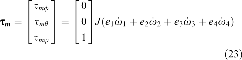
Total torque acting on the helicopter is considered in the body reference frame and can be written as

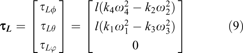
where l is the distance from each rotor to the center of gravity of a helicopter, which is considered to be symmetrical. The torque

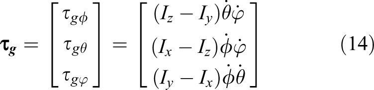
where the variable J is the moment of inertia of the rotor along rotor rotation axis and is the angular velocity of the frame along the roll (ϕ), pitch (θ), and yaw (φ) axes

From equation (11), the gyroscopic torque due to rotor rotation can be expressed as

where ei
is the direction of rotor rotation corresponding to the ith rotor along
The variable

The variable I is the moment of inertia of the frame along
The variable

The maximum torque from a rotor,


Torque due to the drag force acting on a rotor.
We can visualize the drag force on a rotor as shown in Figure 3, where rotor drag force is a function of rotor coefficients and radius r′.
2
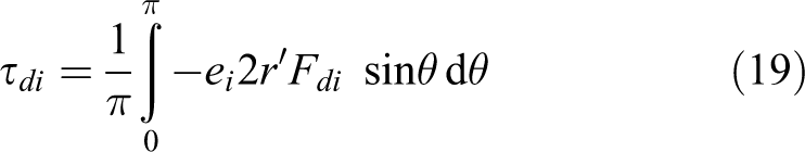
However, since the rotor rotates from 0 to 2 π rad as shown in Figure 3, the torque due to drag force varies with the angle of rotation. The radius of the left and right rotor blades is equal; therefore, the total torque at the rotor position between 0 − π and π − 2π is identical. The drag torque at any rotor angles can be written as


The relation between rotor torque due to drag force and rotor angle.
The torque in equation (18) is the absolute value of sine wave, as shown in Figure 3. Therefore, the average torque from equation (18) can be calculated


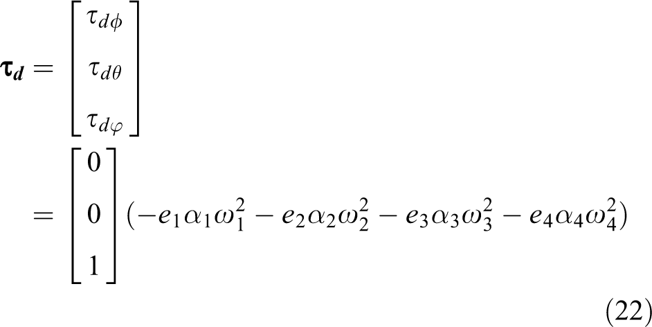
The parameter αi in equation (21) is drag torque coefficient of rotor i which is a positive constant. From equation (21), total drag torque acting on the body frame can be written as
The torque acting on the rotor axis resulting from change of angular momentum of the rotors,
The variable

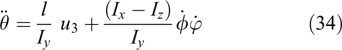
After substitution of all torques in equations (8) to (24), the dynamic model of the quadrotor helicopter can be expressed as

where Ix, Iy, and Iz are the moments of inertia of the helicopter along
Control algorithm
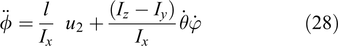
Since moment of inertia of rotor is small compared to that of the frame, the ratio of J/I is very small. Thus, the gyroscopic torques along the roll and pitch axes and angular momentum along the yaw axis, according to equation (25), are small and negligible. When all of the rotor coefficients are identical, the dynamic model is simplified to

Sliding mode control
SMC for the roll angle when all rotors have the same lift and drag coefficients is expressed by the sliding surface and the dynamics equation

Whereas ϕd is the designed roll angle. The derivative of the sliding surface becomes


The equivalent control input
The control input u for the roll angle becomes

Similarly, the dynamic models of the altitude, pitch, and yaw angles can be expressed as
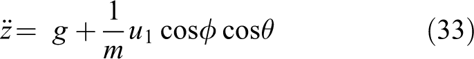

where the control laws for the altitude, pitch, and yaw angles can be written as


where
The proposed SMC
The control law derived in the previous section is based on the assumption that all rotor coefficients are identical. Preliminary experiments have shown that the state outputs (i.e. angle and altitude) were stable but they did not converge to the desired point. To investigate this phenomenon, the Lyapunov candidate function is introduced

The derivative of equation (39) is

From equations (27) and (30)

Based on control law in equation (32), when the controlled states converge to the set points, mean of force u2
from equation (32) becomes zero to produce zero torque, the error term

Normally, u2
is a direct result from the lift coefficient of the rotors, k, and the rotor speed, ω

In practice, if the coefficient k has been changed according to the actual usage, it can cause the nonzero average of u
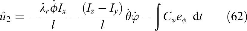
2. According to our experiment, rotor speed ω can be precisely controlled; this leads to my conclusion that the coefficient k of each rotor must be different. Therefore, equation (43) should be rewritten as

Equation (44) indicates that with nonidentical lift coefficients, it does not provide zero torque even though u
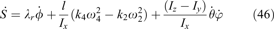
2 from equation (32) is zero, and thus equation (42) is invalid in real system. Since the coefficients k in the dynamic model (25) are not the same, the dynamic model cannot be simplified as expressed in equation (26). For the roll axis, the dynamic model is expressed by

The derivative of the sliding surface is expressed by
In the actual quadrotor helicopter, the lift coefficients k
2 and k
4 are not identical. Define the lift coefficients as the summation of an approximate value k and the correction value ε

The derivative of the sliding surface now becomes

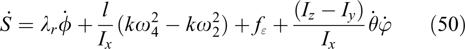
Separate part of the correction value into a new function

The derivative of the sliding surface becomes
Denote the steady state position error as eϕ


Nonidentical parameters cause offset error at steady state. When the mean of eϕ is close to zero, the correction function, fε, converges to the constant value. This constant value is the correction force that is lost due to the approximation k. Let fε denote the mean of correction function

When fε is constant, its derivative is zero

The position error is proportion to the derivative of fε


The variable Cϕ in equation (56) represents a positive constant value. From equation (56), the mean of the parameter error is the integration of position error

When fε and eϕ are uniform-distributed functions, the mean function in equation (57) can be rewritten as


From equation (59), the relationship between parameter error and position error becomes

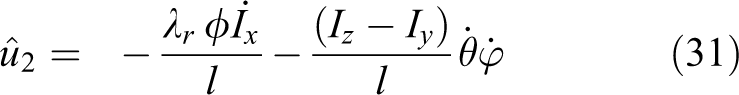
Now substitute equation (60) into equation (48)
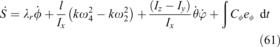
The equivalent control input for the roll angle is determined as
Thus, the control law of the roll angle can be written as

With similar derivations, the control laws for the remaining attitude control can be determined


Parameter identification
Several control algorithms are designed for quadrotors to control dynamics behavior of the quadrotors. In general, the output from control law is the required force of each motor which is determined from the rotor speed using a simple relation between rotor speed and thrust force. However, there is no force control loop to ensure that each rotor produces the force as required by the control law. This problem causes the ideal performance quadrotor differs from the real performance and requires improvement. This behavior was confirmed from the experiments, which showed that the state outputs (angle and altitude) were stable but did not converge to the desired values.
To confirm that the quadrotor rotors have different behaviors, the lift and drag coefficients k and α from all rotors are investigated. From the experimental results, the relations between rotor speed and lift force are obtained as shown in Figure 4. According to the rotor aerodynamic, lift force, FLi
, is the multiplication of square of the rotor speed, ωi, and the lift coefficient, ki
, of the ith rotor

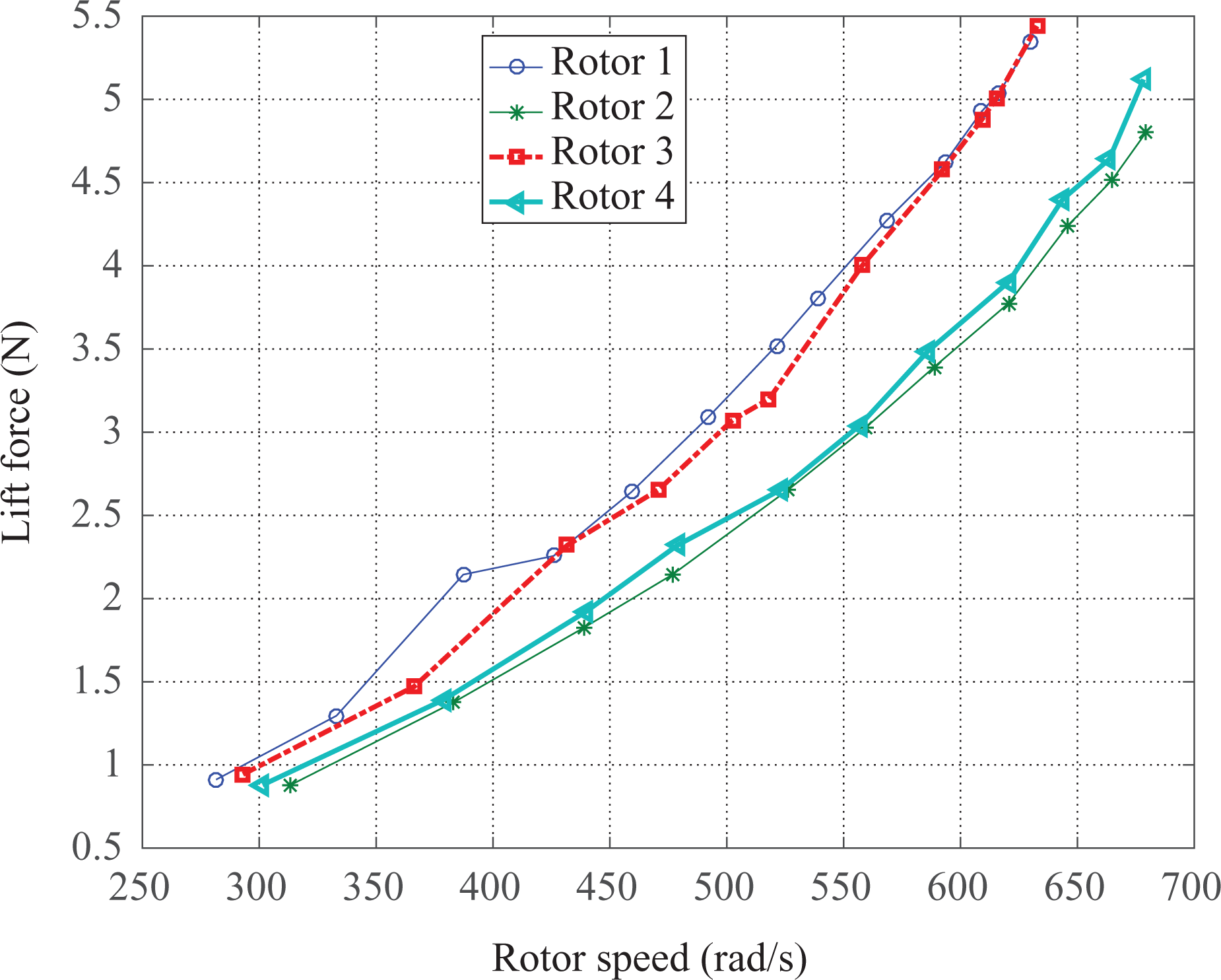
Experimental result of lift force and rotor speed.
The lift coefficient of each rotor is identified using the experimental result in Figure 4 and equation (67). The results from statistical regression are obtained as follows


The drag coefficient is identified from the power and rotor speed relationship. The parameter αi in the dynamic model (21) depends on the rotor characteristic and can be determined by

where Pi and ωi are the power and the speed of the ith rotor, respectively. From the experimental results, the relation between the motor power and the rotor speed is shown in Figure 5.
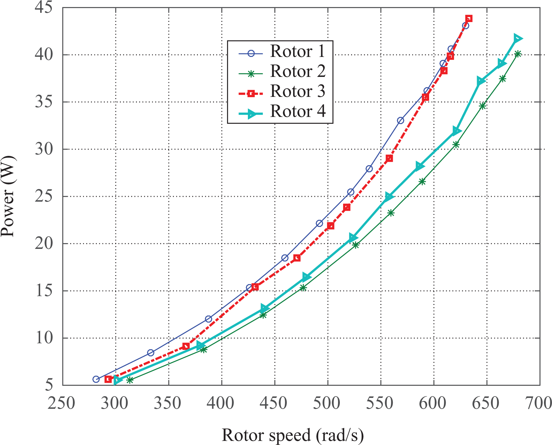
Experimental result of motor power and rotor speed.
Similar to the lift coefficient, the drag torque coefficient of each rotor is determined. Using the experimental results in Figure 5, equation (72), the drag torque acting on yaw axis in each rotor can be computed as follows


From the parameter identification, four different lift and drag coefficients are obtained. However, most of the researches of quadrotor control always assumed identical lift and drag coefficients for all rotors using their average values.
System requirements and design
System requirements
In order to verify that the proposed offset cancellation technique performs efficiently regardless of the size of quadrotor, two quadrotor helicopters are used in this research. They have different sizes, weights, and physical parameters.
Brushless DC motors are used in this work to drive the rotors. The motor power must be sufficient to generate lift force under full load. The selection of motor’s power has been described in Appendix 1. In this work, the motor’s output power is 100 W for the large quadrotor and 45 W for the small quadrotor. A lithium polymer (LiPo) battery with 12-V 3 Ah capacity is used in the small quadrotor and 12-V 5 Ah capacity is used in the large quadrotor. The LiPo battery is suitable as the power source in quadrotor because it provides a high energy but light weight. 17
A 32-bit microcontroller, PIC32MX460F512L-80I/PT, is selected for the processing unit of the quadrotor. It is a powerful microcontroller available in the market and operates at 80 MHz which is sufficiently fast to control the attitude and heading of the quadrotor. The flight data are periodically monitored and sent to the ground computer via Xbee communication module.
Mechanical system design
The gyro sensor and accelerometer modules are installed at the center of both helicopters. The controller board interfaces with the accelerometer via RS-232. Angular rate measurement in three axes of the gyro sensor is obtained through ADC module of the microcontroller. The platforms of the two quadrotor helicopters are built as shown in Figure 6. Their parameters are shown in Tables 1 and 2. Moment of inertia along roll, pitch, and yaw axes of the body frame (including components such as the batteries, motors, drivers, and controller board) are obtained from 3-D drawing in SolidWorks [Version 2010]. The moment of inertia of the rotors and motors are obtained by calculation from the motors and rotors size and weight.

Two quadrotor helicopter platforms.
Large quadrotor helicopter parameters.

Small quadrotor helicopter parameters.

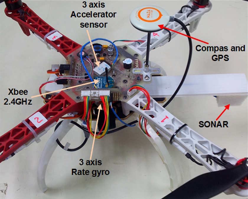
Electronic boards including microcontroller, communication, and sensor modules are installed as shown in Figures 7 and 8 for the large and small quadrotor helicopters, respectively. Sonar sensor is used for altitude measurement when the helicopter flies at low altitude.

Electronic boards and sensors of the large quadrotor helicopter.
Electronic boards and sensors of the small quadrotor helicopter.
Simulation results
To evaluate the performance of the conventional SMC algorithm, as expressed by the dynamic model in equation (26) and control law in equations (32) and (36) to (38) in comparison with the proposed SMC with offset cancellation technique as expressed in equation (63) to (66), simulations are conducted. Since the sensors always contain noises in the output readings, noises are considered in the simulation as well. According to the result from experiment, the measurement noise is zero-mean Gaussian distribution with variance of 0.34. To simulate the real word environment, the noises are therefore added to all measurement readings.
The value of the control parameters is roughly obtained using Lyapunov criteria and fine tuned manually to achieve the maximum control performance. In this work, the same sliding surface and chattering gain parameter are used for the SMC.
Analytic approximation of the control parameter is based on the Lyapunov candidate function in equation (40), and the quadrotor is stable when
This relation is valid by introducing a positive constant M where
This yields to
Apply the sliding surface in equations (27) and (29) into the Lyapunov candidate function in equation (40)

Define E as control distance, which is the distance between the required and the actual positions
Equation (80) can be rewritten as
The control force, u2, and the control distance, E, must be in opposite direction
Equation (83) is a quadratic function which has a minimum point at
From equation (84), the sliding variable, λr, can be determined by
The positive value, M, in equation (79) is the chattering gain which can be obtained by
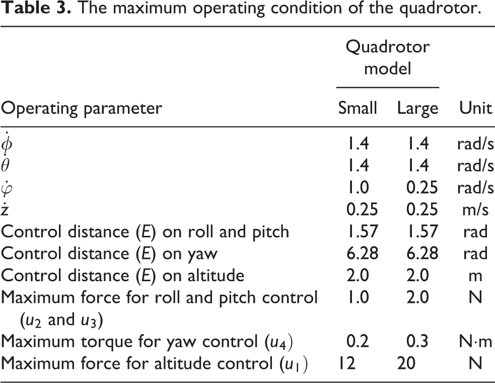
The procedure can be extended to the other control parameters which are determined by the same analytic technique. The maximum angular velocity (
The maximum operating condition of the quadrotor.
The control parameters.

To investigate the influences of the control parameters on the attitude control of the quadrotor, several values of the parameters are applied. The simulation results are shown in Figure 9. From the results, the positive constant M has an influence on the vibration of the quadrotor. With large value of M, the quadrotor vibrates with large amplitude. The sliding variable, λ, has an influence on the response time. With low value of λ, the quadrotor has slow response. In the proposed SMC, the compensation parameter, C, is introduced. With its appropriate value, the attitude response is compensated to have zero (SolidWorks, Version 2010) average error. However, if the value of C is too high, the quadrotor might be unstable.

The influences of the control parameters.
Figure 10 shows the simulation results of the conventional SMC control when all rotor coefficients of the quadrotor helicopter are identical and nonidentical.
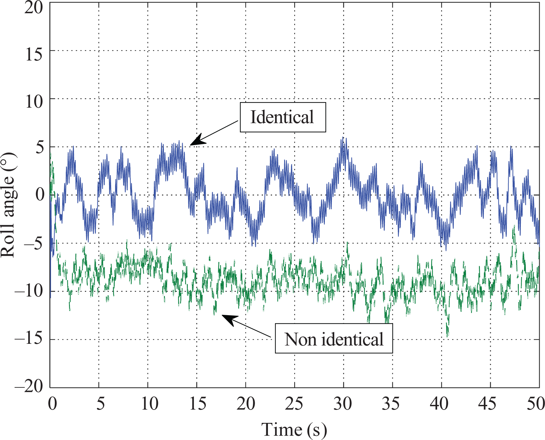
Simulation results of roll angle when the rotors are identical and nonidentical.
When identical rotors are used, the average value of the roll angle error is only −0.0584°. In contrary, the nonidentical rotors cause the average error rise up to −8.74°.
The comparison of control performance of different controllers is shown in Figure 11. With nonidentical rotors along with noise disturbance to the system, both PID and SMCs can stabilize the quadrotor. However, the system still has an offset error. The average value of the roll angle error with the offset cancellation technique is suppressed only to 0.0616°, while the results of the conventional SMC, the adaptive SMC, and the PID are 1.21°, −1.16°, and −1.45°, respectively.

Comparison of different controllers.
From both results, fluctuations of the output are observed. These fluctuations are caused from the noises. To eliminate the fluctuation of the output response, a low-pass filter is applied.
The cutoff frequency of the low-pass filter is designed corresponding to the sampling rate. The response of the output when the low-pass filter is applied to the control system is shown in Figure 12. The output with the low-pass filter shows less fluctuation on the output angle.

Simulation results of roll angle with and without a low-pass filter.
The performance of the proposed SMC with offset cancellation technique is seen from the simulation results as shown in Figure 13. The simulation is based on nonidentical rotor parameters. The conventional SMC results in offset error in the output, while the proposed algorithm successfully controls the output to the desired angle of 0°.

Performance comparison of the conventional SMC and the proposed SMC with offset cancellation technique. SMC: sliding mode control.
Experimental results
The experiments are conducted on two quadrotor helicopters with nonidentical rotor parameters. Both helicopters are controlled using the same algorithm.
The experimental results in Figures 14 and 15 show the roll and pitch angles from the large quadrotor helicopter when controlled by the conventional SMC compared with the proposed SMC with offset cancellation technique. Due to nonidentical characteristic of the rotors, the results of conventional SMC shows 1.35° offset error in roll angle and 7.47° offset in pitch angle, while the proposed SMC with offset cancellation technique reduces the offset error to −0.25° and 0.08° for roll and pitch angles, respectively.

Experimental results of roll angle from the large quadrotor helicopter when applying the conventional SMC and the proposed SMC with offset cancellation technique. SMC: sliding mode control.

Experimental results of pitch angle from the large quadrotor helicopter when applying the conventional SMC and the proposed SMC with offset cancellation technique. SMC: sliding mode control.
From Figures 14 and 15, the experimental results of the conventional SMC stop after 25 s because the offset on row and pitch angles causes the quadrotor becomes unstable and tends to fall; therefore, emergency stop was activated to protect the quadrotor from crash.
Similarly, Figures 16 and 17 show performance comparison for small quadrotor helicopter. The results of conventional SMC show 3.87° and −0.15° for roll and pitch angles, respectively, while the proposed SMC with offset cancellation technique reduces the offset error to −0.09° and −0.14° for roll and pitch angles, respectively.

Experimental results of roll angle from the small quadrotor helicopter when applying the conventional SMC and the proposed SMC with offset cancellation technique. SMC: sliding mode control.

Experimental results of pitch angle from the small quadrotor helicopter when applying the conventional SMC and the proposed SMC with offset cancellation technique. SMC: sliding mode control.
The experimental results from the large and the small quadrotors show that the proposed SMC with offset cancellation technique can force the average tracking error to zero regardless of the quadrotor size.
For the altitude and yaw control, the results are shown in Figures 18 and 19, respectively. The altitude is set to 1.0 m above the ground, and the yaw angle is set at 0° from north.

Experimental results of altitude of SMC with offset cancellation technique from the large quadrotor helicopter. SMC: sliding mode control.
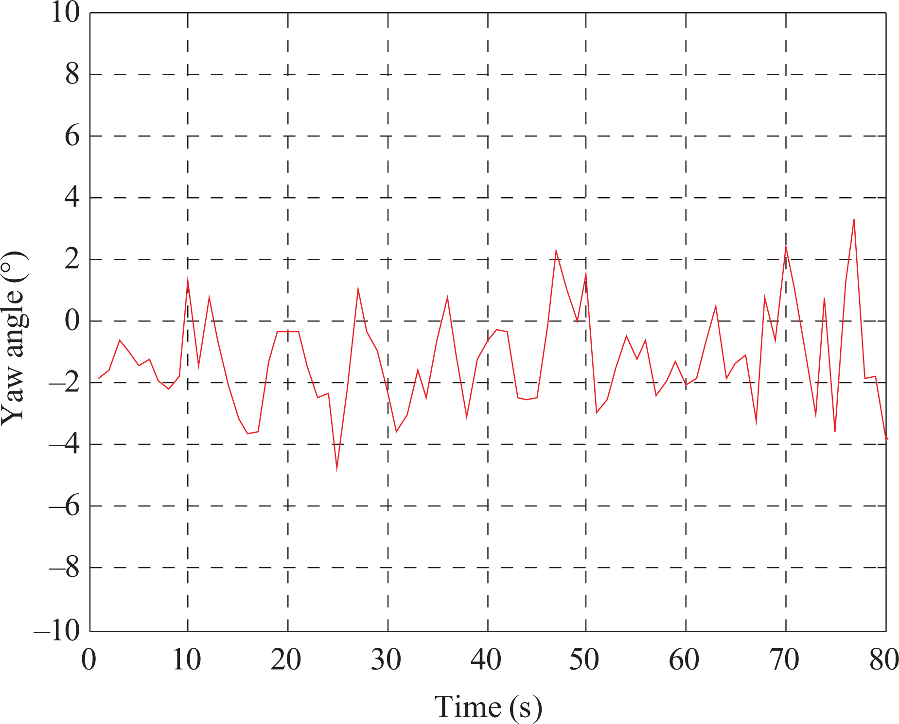
Experimental results of yaw angle of SMC with offset cancellation technique from the large quadrotor helicopter. SMC: sliding mode control.
To evaluate position control performance of the proposed SMC with offset cancellation technique, two experiments are conducted. The first experiment is on hovering control, while the second experiment is on tracking control. The hovering control result is shown in Figure 20. A fixed target position is provided to the controller. The experimental results show that the quadrotor helicopter successfully hovers around the target position.

Experimental results of position control of the proposed SMC with offset cancellation technique. SMC: sliding mode control.
The tracking control result is shown in Figure 21. Four target positions are set as the tracking positions as illustrated by points A, B, C, and D, respectively. With the proposed SMC with offset cancellation technique, the quadrotor helicopter successfully tracks along the predefined path. In contrary with the conventional SMC, the quadrotor helicopter flies aimlessly and does not track the predefined path due to the nonidentical rotor parameters.

Experimental results of tracking control of the proposed SMC with offset cancellation technique. SMC: sliding mode control.
Conclusion
This research proposed SMC with offset cancellation technique to control attitude and altitude of the quadrotor helicopter. Four DC brushless motors are used as the main actuators to generate lift forces to stabilize and control the helicopter motion. The nonlinear dynamic model including the internal and external forces acting on the quadrotor helicopter was derived. The dynamic model was simplified by eliminating the terms with small values such as H-force due to rotor drag and drag force of the frame body. The lift and drag coefficients of the rotor characteristics were identified from the experimental data. The performance of the proposed SMC with offset cancellation technique was then compared with the conventional SMC.
From both simulation and experimental results, the conventional SMC could not remove the offset error, while the proposed SMC with offset cancellation technique could successfully remove the offset error and control the attitude and position of the quadrotor helicopter.
Footnotes
Declaration of conflicting interests
The author(s) declared no potential conflicts of interest with respect to the research, authorship, and/or publication of this article.
Funding
The author(s) disclosed receipt of the following financial support for the research, authorship, and/or publication of this article: Asian Institute of Technology, P.O. Box 4, Klong Luang, Pathumthani 12120, Thailand.