
Abstract
The article presents some aspects of a complex control system of a teleoperated military mobile robot Tactical Robotic System (TAROS) related to virtual reality and assistance to a human operator in general. Described is especially the unique and innovative system of virtual operator station which uses the HMD Oculus Rift to put the operator into a virtual space containing visual feedback from the robot and camera images, including stereovision. The virtual operator station serves as a cost-effective and portable replacement of what otherwise would be a large room with expensive equipment. Mentioned is also another system that helps the operator with remote manipulation tasks – the anti-collision system preventing damage done to the mechanical parts of the robot by incautious movements of the manipulator arm.
Introduction
Mobile robots controlled remotely by trained human operators are nowadays quite frequently used in various fields, especially in those where direct deployment of men would be either impossible (reconnaissance of very constricted spaces, areas with lethal radiation or other dangerous substances, foreign planets, etc.) or extremely dangerous (fire-fighting, explosive disposal, etc.).
The latter category includes also military applications, where the danger of injury or even death of soldiers is unacceptably high and replacing them by machines (robots) is particularly favourable, at least in the most risky assignments. Although mobile robots are still very expensive, a loss of a robot will always be more acceptable than the loss of a human being.
The operator of a remotely controlled mobile robot typically controls the robot out of direct sight and relies purely on data from sensors and cameras – typically displayed in a simple form on a standard screen. 1 –3 This may become uncomfortable or even dangerous if the robot contains, for example, a quite complex manipulator arm with many degrees of freedom and the operator is supposed to perform complicated manipulation tasks.
The Department of Robotics (VŠB-Technical University of Ostrava, Czech Republic) has been developing advanced control systems of teleoperated mobile robots that address these problems by utilizing virtual reality. 4 –6 The latest version was created for the military mobile robot TAROS.
Mobile robot TAROS
Tactical Robotic System TAROS V2 is a science and research project of the Czech company VOP CZ s.p. (Figure 1) It is an unmanned robotic mobile system developed in cooperation with Czech universities in the frame of Center for Advanced Field Robotics established in 2013. 7 The robot was designed for combat and logistical support of mechanized, reconnaissance and Special Forces in a complex and risky operating environment. 8

Military mobile robot Tactical Robotic System (TAROS) V2 (source: archive of VOP CZ s.p.; author: Radim Horák).
The robot can be modularly adapted to actual requirements of the military unit and one of the basic modules contains a manipulator arm with five degrees of freedom and universal gripper, with an overall reach of 2.1 m and load capacity up to 20 kg.
This manipulator module contains cameras mounted near the gripper and the operator controls the arm using the advanced control system with virtual reality.
Virtual operator station
The graphical interface of the control system is designed as an innovative virtual operator station. The system runs on a physical operator station (a heavy-duty case with the computer); but unlike other typical applications, the operator is not watching a screen located in the station. Instead, he is wearing an Head-mounted display (HMD) device 9 Oculus Rift 10 which creates the impression of being in a virtual space (room) – the virtual operator station – rendered by the control system.
The main idea of this approach is to create a much better operator station than it would be physically possible, especially in field conditions. While real operator station could possibly contain only one or several small flat screens, the virtual station can consist of multiple very large screens and even can display stereovision images.
Elements rendered in the virtual station
The content of the virtual operator station is watched by the operator from two virtual cameras located in the 3D space. These two cameras do not correspond to any real physical camera on the robot, their optical parameters are configured exactly for the Oculus Rift requirements (for the best use of the whole Oculus Rift wide angle of view) and their rotation (yaw, pitch and roll) is affected by movements of the operator’s head (by means of the Oculus Rift tracking sensors). This way the operator can freely look around in the virtual space.
The virtual room (Figures 2 and 3) contains several large planes simulating computer monitors (or rather cinema projecting screen) positioned in front of and slightly around the operator. Each screen has the images of some physical cameras mapped onto. The largest plane shows images from the stereovision cameras located on the arm near the gripper. The slightly smaller planes around it show images from the main driving camera located on the chassis of the robot, images from a thermovision camera or night vision camera, and other important data (sensors readings, status icons, warning icons, etc.). Important icons can also be rendered directly over camera images.

Schematic representation of content of the virtual operator station.

Actual image sent to the head-mounted display (HMD) device (contains images for both eyes).
On the ‘floor’ of the virtual room is rendered a small 3D model of the mobile robot that mirrors the actual position of the manipulator arm of the real robot.
Software implementation
The TAROS control system consists of two applications, both programmed in Microsoft Visual C++. One application (‘Server’) is running on the embedded PC located on the robot (see Figure 4) and it is responsible for communication with arm motors controllers. The second application (‘Client’) is running on the control PC located in the operator station. Bidirectional communication between the Server and the Client is done via wireless Ethernet (Wi-Fi). The Client draws the virtual operator station in Oculus Rift by the use of DirectX for rendering and hardware acceleration of 3D graphics.
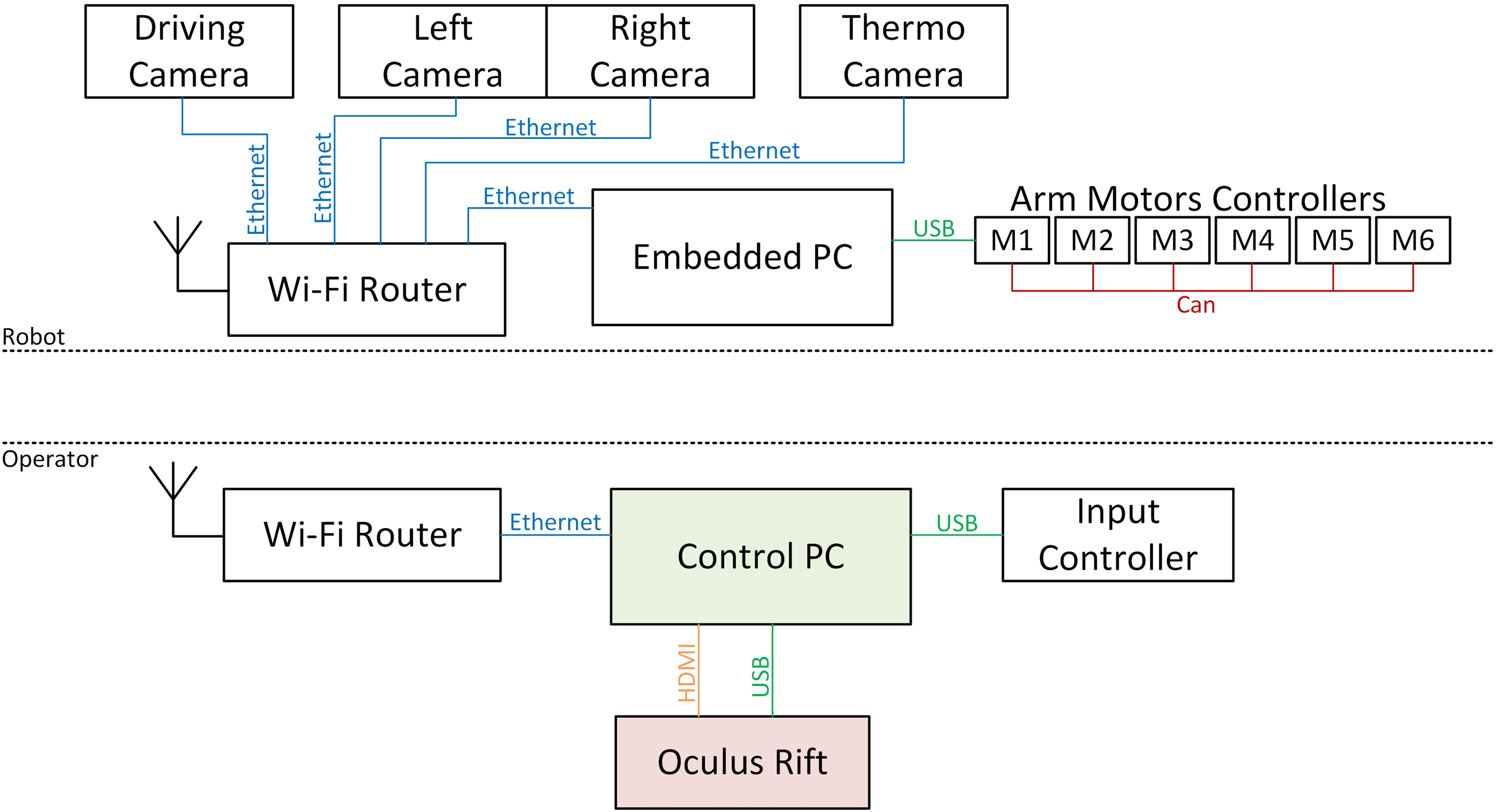
Interconnection of the main hardware components of the control system in the chain robot – operator station.
Screen planes mentioned in the previous chapter are rendered simply as rectangles with a texture filled with actual pixel data of images acquired from the corresponding camera. These planes are aligned with the z-axis (vertical) of the virtual 3D space and are rotated towards the viewer in the other two axes. 3D model of the robot is rendered as a slightly simplified mesh model created from the Computer-aided design (CAD) data.
For display in Oculus Rift, the virtual scene must be rendered twice (once from each virtual camera – eye). The two views are processed by geometric and chromatic post-processing algorithms implemented by the Oculus Rift SDK in order to cancel out the optical deformations happening later in the HMD itself (this happens automatically, and the algorithms are hidden from the programmer), combined into a single picture and sent to the HMD device (Figure 3).
Stereovision cameras
Stereovision cameras (a pair of cameras positioned next to each other in a fixed distance similar to the distance between human eyes) produce a 3D stereoscopic view of the environment around the robot, which can greatly aid the operator especially in manipulation tasks with the arm (depth perception). The question is how to mediate the 3D view to the operator.
The HMD device is very appropriate for this task, given by its basic principle. The most simple and intuitive approach would be to directly display the images from real cameras to individual eyes in the HMD. This would make the user feel like standing at the position of the robot. There are, however, several problems with this solution.
The cameras, in this case, need to have very specific optical parameters, especially a quite large field of view (over 100° diagonally) and very uncommon ratio 9:10 (vertical orientation). Any other values would require the images to be scaled and cropped, which would limit the resulting field of view of the HMD device. There is also another problem – motion sickness. Oculus makes the user feel really immersed in the virtual reality and the brain expects all senses to match what the eyes see. When the robot or the arm with the cameras move around, the images also move; this is in direct conflict with signals from other senses including the inner ear.
After some testing on multiple test subjects (see below), a different solution was chosen – the already mentioned rendering of camera images on a virtual screen plane. In the case of stereovision cameras, the main screen (Figure 3) is rendered with different images for each eye. The resulting look and feel are very similar to watching a screen with the 3D movie in a 3D cinema. This concept, in general, has already been implemented by various authors, for example, Cineveo – Virtual Reality Cinema. 11 The biggest source of motion sickness is removed, because the brain feels to be attached to the virtual space of the ‘cinema’, which does not move.
Test results
The two above-mentioned methods of stereovision camera images display in Oculus Rift were tested on 15 selected people of different ages (from 18 to 65). Every person had some time to get used to the HMD device and then rated his feelings, especially the motion sickness. This was done separately for both methods with a long time between the tests (usually few days). Rating is on the scale 1 to 5 (1 means negligible motion sickness induced after a long time, and 5 means serious motion sickness after a very short time). The following table shows averaged numbers for the 15 persons divided into three groups based on age.
Convergence
The virtual screen plane is rendered in a specific distance from the viewer in the virtual 3D space. The 3D images introduce additional depth information and objects in the images can appear in front of or behind the screen. If the physical cameras have parallel optical axes, objects located infinitely far away (or at least very far away) are placed exactly at the distance of the virtual screen and all other objects are always in front of the screen.
The problem with this basic solution is that the scene appears to be very close, objects in the images seem to collide with the 3D model of the robot and there is huge depth conflict at the edges of the screen plane.
A possible solution is to apply Horizontal Image Translation (HIT) to the images before applying them on the virtual screen planes. This very simple software modification of the images (shifting pixels horizontally) changes the convergence point; the images must be shifted outwards to put the convergence point further away from the viewer. The images must not be shifted too much, because otherwise a pixel could have the resulting overall convergence in the HMD device behind infinity and eyes would not be able to focus on such a point at all (eyes cannot rotate outwards), which creates a lot of eye strain. The maximum possible HIT value is equal to the parallax p max of the screen plane in virtual reality (VR)


where X is the horizontal resolution of the Oculus Rift screen in pixels, ϕx is the horizontal field of view (FOV), d′ is the distance of the projection plane and ds is the distance of the virtual stereovision camera screen plane from the user in the virtual world (in meters).
The p
max value is in LCD pixels, but because the camera image pixels do not map 1:1 to LCD pixels, the images must be shifted by

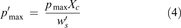
where ws
represents the width of the virtual screen plane (in meters),
With this modification, the impression is improved, because some objects are now placed behind the virtual screen. In typical situations, the HIT value can be fixed (always equal to
3D model of the arm
As already mentioned above, the virtual operator station contains also an interactive 3D model of the robotic arm at its actual position. This helps the operator when he cannot see the arm by other means because thanks to it he knows how the individual joints of the arm are rotated and whether the arm is in a good configuration for his current manipulating task (Figure 5).

Interactive 3D model of the arm and the robot (separated from the virtual operator station).
Individual elements (moving parts) of the 3D model are rendered with a proper transformation matrix generated from the real values acquired from the incremental encoders of the direct current (DC) motors in the arm.
Collision detection and prevention
There was implemented also another practical feature related to the 3D model of the arm and knowledge of the joint positions – anti-collision system. The purpose of this system is to prevent damage done to the arm or other parts of the mobile robot by predicting imminent collisions and overriding the operator’s commands in these situations. 12
The applied solution uses a quite simple but extremely effective and quick method. All parts of the arm and the robot are covered by a set of manually created bounding boxes enclosing the shape of the mechanical parts as tightly as possible (Figure 6).

Visualization of bounding boxes of the Tactical Robotic System (TAROS) arm (red boxes signal a detected intersection of a pair of boxes).
During arm movement, positions of all bounding boxes linked to all moving parts are calculated using extrapolation of the current velocities of arm joints – calculated are positions ‘in near future’

where qi is the real actual angle of the particular arm joint, vi is the corresponding angular velocity and t ext is the chosen extrapolation time.
Extrapolation is necessary because using the actual real positions of the arm joints would detect only an already happening collision and would not allow prevention. The extrapolated positions are then used to make intersection tests between pairs of bounding boxes. The number of all possible pairs of n boxes is

but not all pairs of boxes can practically collide, so it is advantageous to check only predefined pairs. The TAROS model contains 26 bounding boxes (c = 325); checked are, however, only 94 pairs.
If an intersection is found, the system signals this state to the control system of the arm and the drives are either slowed down or completely stopped, based on the estimated severity of the collision – there are two phases of collision calculation; the first phase uses t ext = 0.12 s (a detected intersection results in a slowed down movement) and the second phase uses t ext = 0.03 s (all movements are stopped).
Box–box intersections are calculated using the Separating Axis Theorem, which can be used to detect the intersections of any convex bodies. The theorem says that for any two convex bodies there exists a line (so-called separating axis) onto which their projections will not overlap if and only if the objects are not intersecting. 13,14 Its implementation for pairs of boxes is very fast and requires verification of only 15 potential separating axes. 15 If even a single axis from the 15 possible exists, the intersection is ruled out.
The general shape of parts of the arm is very simple so using boxes as bounding volumes does not introduce excessive error and unwanted reduction of operating volume. The positive effect is extremely effective in box–box intersection tests, so this subsystem does not increase the load on the control system hardware.
Conclusion
The advanced graphical user interface of the TAROS operator control system described in this article is still in development, but a fully functional version has already been implemented and tested on TAROS and on some other mobile robots created by the Department of Robotics, VŠB-TU Ostrava.
The innovative virtual operator station makes control of a mobile robot very intuitive and can mediate 3D view from stereovision cameras with very low cost and without requiring the use of large equipment. Oculus Rift DK1 and DK2 versions were used in the development with very good results. The final consumer version of Oculus Rift further increased the quality of the immersion because of its higher resolution and better frame rate. Testing proved (see Table 1) that the chosen method of rendering induces considerably less motion sickness than direct display of stereovision cameras to individual eyes in Oculus Rift.
Motion sickness rating of the two stereovision cameras display solutions.

Because the operator controls the robot with the HMD device on his head, he is not disturbed by negative effects of his surrounding, including, for example, direct sunlight, which can be uncomfortable when using standard computer screens. This, however, has also a disadvantage – the user cannot see sources of potential danger around him. This could be addressed in the future development by attaching cameras to the HMD device and showing their images in the virtual environment.
Real-time rendering of a 3D model of the arm together with the anti-collision system described in the last part of the article has been already thoroughly tested in many practical applications and proved to be very effective, because the operator can focus his concentration more on the actual manipulating task rather than on work with the manipulator arm.
Footnotes
Authors’ note
This article has been elaborated in the framework of the specific research project HS3541602 in cooperation with VOP CZ s.p. and the project Research Centre of Advanced Mechatronic Systems (CZ.02.1.01/0.0/0.0/16_019/0000867) by Ministry of Education, Youth and Sports, Czech Republic.
Declaration of conflicting interests
The author(s) declared no potential conflicts of interest with respect to the research, authorship, and/or publication of this article.
Funding
The author(s) received no financial support for the research, authorship, and/or publication of this article.