
Abstract
Path planning under uncertainty in an unknown environment is an arduous task as the resulting map has inaccuracies and a safe path cannot always be found. A path planning method is proposed in unknown environments towards a known target position and under pose uncertainty. A limited range and limited field of view range sensor is considered and the robot pose can be inferred within certain bounds. Based on the sensor measurements a modified map is created to be used for the exploration and path planning processes, taking into account the uncertainty via the calculation of the guaranteed visibility and guaranteed sensed area, where safe navigation can be ensured regardless of the pose-error. A switching navigation function is used to initially explore the space towards the target position, and afterwards, when the target is discovered to navigate the robot towards it. Simulation results highlighting the efficiency of the proposed scheme are presented.
Keywords
Introduction
Autonomous navigation of mobile robots is an area of research with increasing interest over the years. 1 Tasks such as area coverage (exploration), 2 –5 surveillance, 6 search and rescue missions require that the robots move efficiently in the environment, avoiding obstacles during motion and keeping under consideration the robots’ physical constraints.
The majority of research on motion planning in the past few decades focused on known static environments, 7 relying on principles such as the artificial potential fields, 8 the vector field histogram, 9 probabilistic roadmaps 10 and rapidly exploring random trees (RRT). 11 In later years, the dynamic window approach 12 has emerged based on the necessity of navigating in dynamic 13 or uncertain 14,15 environments, where most popular navigation methods can be inefficient. 16 Navigation in this case is based on local real-time obstacle avoidance, where onboard sensors can provide information regarding the environment in the robot’s neighbourhood. 17
While on entirely unknown environments, a similar approach can be employed 18 ; the sensorial information can be utilized for an online map building process and the exploration process can be involved in the navigation. In classic exploration strategies, 19 the robot is considered to move towards areas that provide new information about the environment, considering perfect knowledge of the position of the robot. One of the first methods is the frontier exploration method, where a frontier is the boundary between the explored and the unexplored space.
With the identification of the frontier candidates for exploration, a selection must be made. Yamauchi 20 in his work proposed movement closest to the robot frontier. The MinDist approach, as it is referred in the literature, has been similarly used in the works of Santosh et al. 21 Gonzalez-Banos and Latombe 22 instead proposed a cost function that involves the utility of a frontier. Similar approach has been presented by Burgard et al. 23 In both cases, the cost function produces a new target point on the selected frontier and a path planning—usually shortest path—method is used to guide the robot towards the selected point in the frontier. In Haumann et al. 24,25 instead of selecting a frontier, the authors propose a control law, where all candidate frontiers have an impact on the movement and the frontier exploration is coupled directly with the path planning.
While recent sensors, such as Light Detection and Ranging (LIDAR) and vision-based systems, provide accurate environment information measurements, pose information given by Simultaneous Localization and Mapping (SLAM) 26,27 techniques contain some uncertainty. Navigation becomes an issue, as the resulting map becomes inaccurate and this must be taken into account for the motion planning phase. Because of this, integrated exploration strategies have emerged, where effort is made to reduce the imposed uncertainty. Sim and Roy 28 proposed a method, where the uncertainty is reduced by evaluating the information gain of candidate’s future poses and selecting the optimal one. Similar stochastic method has appeared in the work of Vallvé and Andrade-Cetto. 29 These methods reduce the pose error at the expense of computational cost, as they require to compute possible future poses and find in the computed space the optimal one at each step. A much simpler solution for the reduction of the pose uncertainty is the relocalization of the robot either through loop closures 30 or revisiting known positions. 31
In the aforementioned integrated exploration strategies, there are some inherent drawbacks. Most strategies calculate the new position in discrete space which is suboptimal 32 and any local planners that are utilized to guide robots between path points 33 are not modified to account for the uncertainty resulting into control actions that might be unsafe when the robot moves close to obstacles.
The authors aim to provide a solution to the problem of navigating a mobile robot in an unknown environment with a known target position and under uncertainty. Here, the robot is equipped with a limited field of view and range sensor, whereas in other reported research efforts 34 an omnidirectional sensor was considered. The robot state is augmented with the orientation apart from the position, and pose uncertainty is introduced, that can be inferred within certain bounds. The approach utilized in this work expands the concept of the classic exploration, where instead of improving the SLAM procedure, the uncertainty is taken into account via the transformation of the sensor readings to create a modified map, where safe navigation of the robot can be ensured.
Specifically, the contribution lays within the calculation of the guaranteed visibility and from it the derivation of the guaranteed sensed area, subspaces of the initial instantaneous and aggregated sensed areas, respectively. While the target position is not within the guaranteed sensed area, the exploration phase occurs, where the maximization of a navigation function is utilized to guide the robot towards it through frontier-based exploration of the unexplored space. Frontier selection is done via the minimization of a cost function that involves the utility of the frontier towards the desired navigation and the vicinity of it to the robot. When the target position is discovered, the control law switches to a distance from target-based navigation function to reach it through a gradient ascend control law.
The article is structured as follows: (a) mathematical preliminaries are provided along with the problem formulation and the definitions and computations of the guaranteed visibility and guaranteed sensed area, followed by (b) the derivation of the control law, (c) simulation studies outlining the efficiency of the proposed method and (d) concluding remarks.
Problem Formulation
Mathematical Preliminaries
Consider a path-connected topological space
The Minkowski sum of two spaces
Given the collection of all paths {γk} that connect two arbitrary points
Definition 1
Let us consider

Path connected space (a) and visibility subspace from an arbitrary position (b).
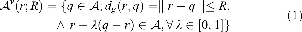
Definition 2
Consider a point
Problem Statement
Let a path connected space,

At any time instance, a sector visibility subspace

created by the range sensor is defined, while
The following kinodynamic robot model is assumed
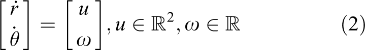
a commonly used 4,35,36 simplified version of the Dubin’s car model that incorporates both the position and the orientation of a robot into the robot dynamics.
Under the assumption of noisy position and orientation measurements the robot’s state vector


Visualization of the areas
A switching objective function is formulated, where subsets of spaces
Guaranteed visibility and guaranteed sensed area
The imposed uncertainty affects the navigation by incorrect estimation on the created global map of the sensed area boundaries which can be described by a collection of l disjoint segments,
All range sensor measurements can be described in the local frame by a pair of polar coordinates
Two additional spaces are introduced, namely,

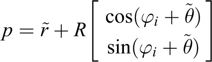
The locus

It is apparent that the locus forms a circular arc around point

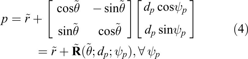
From equations (4)—and (6) the instantaneous visible uncertainty space

It should be noted that while for the initial collection
With the definition of

where R and ψ are reduced to R − εd and ψ − 2εθ to amend for the uncertainty.
The above process is summarized in Figure 3. In Figure 3(a) the initial sensed area

Visualization of the sensed space with the pose uncertainty (a), and boundary uncertainty space with the guaranteed visibility and the various boundaries (b).
The boundary
The cumulative guaranteed sensed area,

Exploration and Navigation Objective
With the definition of
Maximize the following function

during exploration phase,
2. Maximize the function,

during navigation to the goal position, where:
These performance and navigation functions are spatially varying, and their selection navigates the robot closer to the target area.
Path Planning under Uncertainty
During the exploration phase, since the target has not been within the robot’s cumulative guaranteed sensed area
Control Law Derivation
Theorem 1
Consider a robot with a sensing pattern of a circular sector with field of view angle ψ and range R, governed by its kinodynamics (equation (2)). If

where

Proof
For the remainder of this proof, for notation simplicity, the arguments of functions f and φ will be omitted. By differentiating equation (10) with respect to

where n is the outward unit normal vector to
From the decomposition of the boundary

Equation (13) is thus transformed to

The Jacobian matrix

For the second term,
where ϕi is an angle parameter defining each point. Applying the above equation into the Jacobian yields

For the third term, p can be expressed as

Since p is dependent only on the position of the robot

Considering

and the Jacobian can thus be given from

For the fourth term similarly, p can be expressed as

As mentioned, the two line segments

Summarizing the above analysis, equation (15) takes the form

where
Using

As mentioned in problem statement section, this control input is applied to the robot until the target area is discovered, at which point the control law switches to a navigation function based on the shortest distance to target,
Exploration Frontier Selection
Having calculated the control law, functions f(p) and φ(p) should be selected in an intelligent manner in order to encapsulate the need not only to explore the area but also the preferred movement towards the target. As mentioned, the overall scheme is based on a frontier exploration method. For this reason a suitable cost function should initially be formulated for frontier exploration selection.
Boundary
The frontier selection scheme should take into account: (a) the proximity of the frontier to the target, (b) the proximity of the robot to the frontier and (c) the accessibility to new unexplored areas.
To implicate the proximity to target the introduction of the complimentary unexplored space

that comprises a collection of simply connected disjoint subspaces. The frontier search is then limited to those frontiers that are boundaries of the disjoint subspace

where

Visualization of areas
Performance and weighting functions selection
Performance function f(p) implicates the exploration process into the objective given by equation (10) and weighting function φ(p) implicates the navigation towards the desired position, while both the performance and weighting functions are selected so as to be area independent. The performance function will be defined as

This selection ensures that areas near the exploration frontier will be of greater importance than areas further away from it. By ignoring the weighting function, by intuition the robot would move towards the middle area of the frontier expanding it in a uniform manner. This alone could lead the robot to expand the neighbourhood of the frontier that will be further away from the target and thus potentially fail to reach it. To avoid this the weighting function φ(p) is defined as


It must be noted that
Simulation studies
The efficiency of the proposed scheme is verified through two different simulation scenarios. Two different areas for navigation were created that are depicted in Figure 5, where for visualization purposes the initial (green dot) and the target position (black dot) are illustrated.

Ω-sample areas for navigation.
In the first scenario (Figure 5(a)) the rectangle encapsulating the convex hull of Ω is of 14 m × 12 m. The robot has a range sensor of R = 1.6 m and ψ = 1.047 rad, while the error bounds of equation (3) are given from εd = 0.05 m, εθ = 0.087 rad. At each time instant, the robot moves according to control law (12) with a maximum translational velocity of ν = 0.1 m/s and angular velocity of ω = 0.1 rad/s. The weights of equation (23) are selected as w1 = 0.8, w2 = 0.6 and w3 = 0.4. Boundaries of
In Figure 6, the evolution of the navigation towards the target area is seen, where the ‘light grey’ area depicts the unknown space, the guaranteed sensed area corresponds to ‘light blue’ and the boundary uncertainty space

Evolution of the robot navigation towards the target location with respect to the actual area [First scenario].
In the second scenario (Figure 5(b)) the area under investigation is of 14 m × 14 m. The robot’s range sensor is defined by R = 2 m and ψ = 1.4 rad, while the error defined by space (3) has parameters εd = 0.05 m, εθ = 0.175 rad. Maximum translational velocity of the robot is selected as ν = 0.2 m/s and maximum angular velocity as ω = 0.2 rad/s. The weights of equation (23) are kept the same as in the first scenario while the grid resolution is kept at 0.02 m. In Figure 7(a)–(f) the evolution of the navigation towards the target area is seen, where the colour coding is unchanged. It should be noted that the more clustered environment of this scenario and the larger bounded error in orientation results in significantly larger areas of

Evolution of the robot navigation towards the target location with respect to the actual area [Second scenario].
Conclusions
In this article a novel method for navigation in unknown environments by a mobile robot with pose (position/orientation) uncertainty is presented. The robot is equipped with a ranged sensor with limited sensing range and field of view while its position/orientation measurements can be inferred within certain bounds. Taking into account a target location in the unknown area and the sensed boundaries, the robot proceeds to find the guaranteed visibility
Footnotes
Authors’ note
A shorter version appeared in the proceedings of the IFAC 2017 World Congress.
Declaration of conflicting interests
The author(s) declared no potential conflicts of interest with respect to the research, authorship, and/or publication of this article.
Funding
The author(s) disclosed receipt of the following financial support for the research, authorship, and/or publication of this article: This work has received funding from the European Union Horizon 2020 Research and Innovation Programme under the Grant Agreement No. 644128, AEROWORKS.