
Abstract
This article deals with methods of navigation and mapping of mobile robots in an indoor environment, for example, laboratories, building corridors, and so on. It explains the proposed solution of global navigation in more detail through the application of potential field method and its transformation into the topological map. Two separate software tools were designed for simulation of wheeled mobile robot behavior in the authors’ workplace. The first software uses the metric form of space representation and it can simulate tactic level of global navigation, while the second one deals with its transformation into the topological map and can be used for strategic level of global navigation. This is how we can get the so-called multilayer map system suitable for different tasks of mobile robot navigation and path planning.
Keywords
Introduction
Progress is constantly being made and new applications are constantly rolling out in the area of robotics as well as in its specific branch, namely mobile robotics. This field is mainly focused on the development of suitable mobile robotic devices, methods, special algorithms, and on finding their appropriate applications in real world. The most distinguished characteristic sign of a mobile robot is its locomotion in space.
The reasons for development and practical application of mobile robots vary. Some of them are to increase the safety level of processes, their reliability, and to continuously drive production efficiency (these are also the most important reasons for their application in industry). 1 The safety of the human operator (nuclear power plants), difficult accessibility (space missions), and so on are also among those reasons. The robots can be applied as a transport system within the factory, 2 they can co-operate with standard industrial robots in robotic cells, and they can be used like cleaning or other kind of service devices too. 1,3 At the same time, mobile robots are becoming closer to human beings with their moving closer to our families. 4 Those are the mobile robots for autonomous vacuum cleaning, grass cutting (in a garden or in football fields—Hameed et al. 5 ), sport and free time activities 6,7 or as helpmates for Ambient assisted living systems, 8 and so on. According to its application, any mobile robot can have a different level of its autonomous behavior. The highest level is represented by autonomous mobile robots (AMRs). 9 Specialists at many universities and research institutes are engaging in research and development in this field. 1,10
According to their definition, AMRs must be able to learn and to navigate the model of the environment to which they are deployed. Research in mobile robot navigation has produced two major paradigms for mapping indoor environments: grid-based and topological. 11 While grid-based methods produce accurate metric maps, their complexity often prohibits efficient planning and problem solving in large-scale indoor environments. On the other hand, topological maps can be used much more efficiently. Accurate and consistent topological maps are often difficult to learn and maintain in large-scale environments, particularly if momentary sensor data are highly ambiguous. By combining both paradigms can be gained advantages of both worlds: accuracy/consistency and efficiency. 11 Integration of both methods is mentioned in Zavlangas and Tzafestas. 12 as well as in other literature sources. 8,9
Recently, many researchers have dealt with the design of control laws for obstacle avoidance and path planning of wheeled (as well as other locomotion systems) mobile robots. 4 Many different methods have been proposed in the literature by Siegwart and Nourbakhsh, 1 Zheng et al., 4 Zavlangas and Tzafestas., 12 Thrun, 11 Hedjar and Bounkhel, 13 Shi et al., 14 and their colleagues, dealing with obstacle avoidance for mobile robotics during last years. The well-known methods among them are the so-called reactive approaches, which have been proposed mainly for a single mobile robot path generation and which are suitable for real-time navigation in unknown environments. During the last two decades, many authors have extended some of those to navigation of multiple mobile robots. Significance has been attributed to potential field approach, 15,16 the vector field histogram, the curvature method, and the dynamic window approach. 13 Approaches called A* 17 and D* 18 can also be considered suitable path planning methods.
Nowadays, we also witness a massive development in the capability of designed control systems suitable for mobile robots. In their work, Turygin et al. 19 proposed the method of enhancing the reliability of mobile robot control process via reverse validation. According to the work of Zheng et al., 4 the tracking control problem for extended non-holonomic chained-form robot systems has received increasing attention and so has the global finite-time stabilization problem in the last few years. The basic idea of these algorithms is based on the parameters measured by the sensor and on drawing of an environmental map around the mobile robot, with the aim of avoiding a collision between the robot and the wall object in its path. 4 Zhao et al. 20 describe the novel iterative learning path-tracking control for non-holonomic mobile robots against initial shifts. Matik and Uricek 8 and others describe approach called simultaneous localization and mapping (SLAM) based on simultaneous localization and mapping. There exists a wide range of sensors suitable for space data measuring. Nowadays, the sensor Kinect has gained notoriety for measuring 21,22 or scanning of the mobile robot environment.
For more flexible navigation, the so-called adaptive finite state machine method was proposed by Shi et al. 14 This method integrates the artificial neural network (ANN) classifier with the traditional finite state machine method. As its results make obvious, a robot can be trained/adapted through ANN to recognize a complex set of state changes. Other approaches of artificial intelligence in mobile robotics can also be applied, such as genetic algorithms 23 and fuzzy methods. 16 Therefore, the role of suitable simulation tools gains in importance not only in case of industrial but also in case of mobile robots. 24,25
The massive development in the area of mobile robotics inspired the authors of this article as well. They too have decided to do some projects on the topics of mobile robot navigation during the last few years. In addition to the conceptual undercarriage 8,10 design of several different mobile robots, a special software tool has been underdeveloped for simulation of mobile robot navigation, path planning, and control with application of metric maps as well as software for map transformation between metric and topological map system. Both software applications are still in the process of development and are planned to be joined together in the near future. This article describes an approach that integrates the application of both map types for mobile robot navigation: grid-based and topological. The functionality of both software tools is demonstrated in a set of simulation tests.
Simulation of mobile robot path planning in metric and topological maps
In general, the main purpose of mobile robot navigation is to find a collision-free path between the start and the target (goal) position in a space with obstacles. Navigation strategies can be divided into several groups according to the method of sensor data processing, representation, and type of environment as well as level of path planning. At the bottom, there is a mere reactive control, where the nearest surrounding space is scanned and the robot tries to avoid the collision with any obstacle detected in front of it. Local navigation, which also deals with localization, is the next level. When the surrounding space is known and the mobile robot has its own map, we can speak about global navigation and path planning. The case when the mobile robot tries to find the collision-free path between two points can be denoted as tactic level of global navigation. The motion between more than two points according to a defined scheme can be considered the highest level and is often called the strategic level of global navigation. 9,10
In our case, we decided to develop two separate software tools for simulation of mobile robot navigation processes in metric and topological maps: Main simulation software named “Mobilny Robot v1.0” (main screen is shown in Figure 1(a)) designed for simulation of local as well as tactic level of global navigation in metric maps. Simulation software named “Transformacia” (main screen is shown in Figure 1(b)) designed for transformation of metric map into the topological map structure. Main screen of software “Mobilny Robot v1.0” (a) and software “Transformacia” (b); both designed at authors’ workplace.

Multilayer map system
Next step consists of proposing a suitable form of environment representation. As it was already mentioned in the Introduction and in the work of Tuzinsky, 25 Duchon and Murar, 26 Jurisica and Murar, 27 and others, there are two major paradigms for mapping indoor environments: grid-based (metric) and topological. Besides these, there also exist other types of map representation.
As mentioned by Zheng et al., 4 grid map–based navigation methods achieve self-navigation while reducing the cost of resources and promoting the running efficiency and speed. In general, grid maps can be divided into two-dimensional (2-D) and three-dimensional (3-D) 14 grid maps, where objects are described by their shape and dimensions. While the traditional 2-D grid map contains less environmental information, the application of a 3-D grid map may be more resource consuming. 4 Occupancy grid, polygonal map or the quad tree representation 15,25,26 can be considered an example. These methods may also have some drawbacks. For instance, in the standard potential field method, the singular point may cause the robot to stop at a certain position, and the robot may show decision jitter problem under complex environment.
On the other hand, the topological maps describe the space by a graph where the nods represent the rooms, corridor corners, elevators, charging stations, or other significant places important for the robot action. Connections and possible routes are represented by the linear segments (edges) between these nodes. This approach can reduce the amount of data for processing and storage, unfortunately together with reduction of map and motion accuracy. Topological maps can also be assigned the Voronoi diagram or generalized Voronoi diagram mentioned by Duchon and Murar 26 and Jurisica and Murar. 27
There exists also a so-called hybrid map system, where the basic structure of the workspace is described by a graph but the structure of any node can be described in more detail by a metric map.
Our simulation software is designed on the basis of a simple form of a so-called multilayer map system. The idea of multilayer map system is based on a concurrent working with several different map types—for example, the metric, the topological, or the hybrid map structure. Each map is placed onto one layer and we can transform the data structure from one layer to another one. Then it is possible to choose or combine the most appropriate map for each task and to switch between them. 9
Simulation software for path planning in metric maps
This simulation software called “Mobilny Robot v1.0” was designed in programming language Microsoft Visual Basic for operational system Windows. It is designated for a three-wheel mobile robot with differential controls and it can simulate the robot motion in 2-D indoor spaces like, for example, warehouses, corridors of any public buildings, office spaces, hospital buildings, and so on. With respect to these conditions, a mathematical model of three basic features must be created
9,10
: mathematical model of the mobile robot and its motion in the space (according to the type of locomotion system), mathematical model of the sensors that the mobile robot is equipped with (e.g. ultrasound contactless sensors, tactile sensors, laser scanners, etc.), mathematical model of space surrounding the mobile robot (coordinate systems connected to the MR and to the space map, relations determining the calculation of the coordinate transformation between the coordinate systems connected with the robot and the map, etc.).
A mathematical model of a mobile robot contains odometry-based localization simulating the counting of virtual data pulses from two incremental sensors (encoders) fixed on both driven wheels. The results are given in the form of global coordinates X and Y. Obstacle avoidance is based on the simulation model of two ultrasound sensors mounted over the front bumper of the simulated mobile robot. These sensors are represented by a model which tests all map cells in the range of the simulated sensor (area described by limit curves—two straight lines and one circle).
Path planning in metric maps
The occupancy grid (metric map) is used for the task of local navigation. Consequently, it is transformed to the discreet form of a potential field for the task of tactic level of global navigation. First of all, the size of each mesh of the grid map should be determined, as it can affect the level of difficulty of calculations by means of which the map is scanned in the grid. Generally speaking, the size of each mesh could be determined according to the size of the simulated mobile robot. The occupancy grid (Figure 2(a)) can be designed in our simulation software or can be downloaded from external text or image file. The task of local navigation (example, see Figure 1(a)) is based directly on this occupancy grid.

Principle of standard global navigation (tactic level), based on the application of potential fields in simulation software “Mobilny Robot v1.0” designed at authors’ workplace: (a) metric map in the form of the occupancy grid, (b) generated obstacles potential field, (c) generated final potential field, and (d) final path.
The task at the tactic level of global navigation is solved by the method of potential fields implemented in main software. The general method is known and described in the work of Voros, 15 Duchon and Murar, 26 and others. As it was mentioned in Bulej’s 9 article for selected space, a scalar function called the potential is constructed being at its minimum when the robot is at the goal point, whilst showing a high value when the robot encounters obstacles. Everywhere else, the function is sloping down toward the goal, so that the robot can reach the goal point from any other point following the negative gradient of the potential.
In our software, the opposite direction of gradient was applied (the value is increasing with the increasing distance from the nearest obstacle). The potential fields’ generating process was divided into three basic steps (Figures 2 and 3), mainly with respect to easy modification of goal point
9
:
generation of the so-called obstacles potential field (see Figure 3(b)), generation of the so-called goal potential field (see Figure 3(c)), generation of the so-called final potential field (see Figure 3(d)).

Path planning process in main simulation software “Mobilny Robot v1.0” divided into three main steps: (a) metric map in the form of the occupancy grid, (b) generated obstacles potential field, (c) generated goal potential field, (d) generated final potential field, (e) planned path—output from path planning simulation. (MR1: mobile robot no. 1 (smaller one); MR2: mobile robot no. 2 (bigger one)).
Solution to mobile robot deadlocking
This method generates positive results when the robot’s dimensions are smaller than the width of any corridor or door on the map (Figure 3, marked as MR1). But what will happen if we use a bigger robot (marked MR2, for example)?
According to our prediction, it can lead to its “deadlocking” in some subspace, separated by narrow door or corridor (we can call it a bottleneck; see Figure 4(d), bounded by ellipse) from the main space, or it can lead to abortion of generated trajectory.

Solution of mobile robot deadlocking in the main simulation software “Mobilny Robot v1.0” by modification of the final potential field generation process: (a) metric map in the form of the occupancy grid, (b) generated obstacles potential field, (c) to (e) standard method leading to deadlocking of mobile robots in some subspace, (f) modification—goal and final potential fields generated in the same time lead to space division into reachable and inaccessible space, (g) planned path (MR1: mobile robot no. 1 (smaller one); MR2: mobile robot no. 2 (bigger one), SP: start point; GP: goal point).
This situation is shown in Figure 4(d) and (e) and it was mentioned also in the work of Shi et al.
14
We have proposed one possible solution, by means of which the previously mentioned method with three steps can be replaced by a “two-step” process (Figure 4—follow red curved arrow (order: (a)–(b)–(f)–(g))): Firstly, the obstacles potential field (Figure 4(b)) is generated like in the previous case and next, on the basis of data extracted from this one, then the goal and the final potential fields are generated together (both in the same time, Figure 4(f)).
Finally, the collision-free path planning (Figure 4(g)) is using the data from the final potential field, which is based on joint effects of both, attractive and repulsive fields. After this modification can start an interaction between waves which might result in the field discontinuity. 9,15 These areas show the traffic ability of action space by certain settings (robot’s dimensions, etc.) and also places, which are not available (white areas in Figure 4(f)). Goal point, start point (SP), possible SP, and wrong SP are shown in Figure 3.
Software for transformation of the metric map into a topological map
As it can be seen in Figures 2 to 4, metric maps are useful for path planning between two points. When we want to prepare more complex plan for mobile robot motion (e.g. “go from room A to room B, than C, etc.”), it cannot be done this way. One possible solution is to use another type of a map. Topological maps appear to be a better alternative for such applications.
There are two possible methods of obtaining topological maps: direct construction of topological maps, indirect construction of topological maps.
The process based on previously created other map type can be considered as one example of indirect method. It can be the metric map mentioned above in our case. Finally, the multilayer map system is done after this step.
We used a programming language Microsoft Visual C# to create our second software (named “Transformacia,” see Figure 1(b)) designed for map transformation from the metric to the topological form. This software requires a computer with the Windows Vista or Microsoft.net Framework 4 operational system addition. The program was tested on both, the 32- and the 64-bit operating systems Microsoft Windows Vista, 7 and 8.
Transformation process
The topological structure inside the metric map can be created by the method similar to the “method of inscribed circles” known from the foundry industry. This method is based on sequential construction of the largest possible inscribed circles (or another suitable shape) between the obstacles. One or more local maxima can be found in each circle (shape), which will form the centers of the next circles. Center points define the path in the middle of all obstacles. We must decide which geometrical shape will be used for local maximum searching. Two options appear—a circle projected onto the orthogonal grid or a square shape. We have decided for a square shape, which fits our condition better. The map loaded in matrix form has an orthogonal structure and the robot can move in eight possible directions—right (+X), left (−X), up (+Y), down (−Y), and in four other diagonal directions (rotated under the 45° angle about the Z-axis with respect to the main coordinate system XYZ). The proposed method of map-type transformation can be divided into several steps. Based on this proposal, we have created the algorithms that have been implemented in our software.
The transformation process consists of the following steps.
Step 1: The repulsive potential field (obstacles potential field) is generated by our first software mentioned in the previous chapter (“Mobilny Robot v1.0”) for a selected metric map. The potential field is displayed as a matrix of values, which rises away from any obstacle (it corresponds to the distance between the mobile robot and the nearest obstacle).
Step 2: Subsequently, this potential field is imported into our second software (“Transformacia”) in the form of a text file (suffix txt or dat). The variables which store the value of global maximum and position are initialized (MAX = 0, coordinates i and j are set to [1, 1]).
Step 3: The global maximum is identified and its value as well as coordinates are stored in reserved variables.
Step 4: The first square is constructed around the global maximum of the size equal to the distance from the nearest obstacle.
Step 5: All local maxima in the square circumference are identified.
Step 6: Around each local maximum the next set of squares is constructed of the size equal to the distance from the nearest obstacle. This process is repeated until they cover the whole map.
Step 7: All square centers (local maxima) are connected by liner graph segments connected to each node, which creates the kind of a topological map.
Finding of the global maximum and the first square
The searching process starts from the first cell H 1,1 in the first row. The whole field is explored by an algorithm for global maximum searching. Global maximum is the point where the distance from the nearest obstacle is the largest in the whole map. If there are multiple cells with the same value, the last one is stored to the variable MAX (see the algorithm in Figure 5(a)).
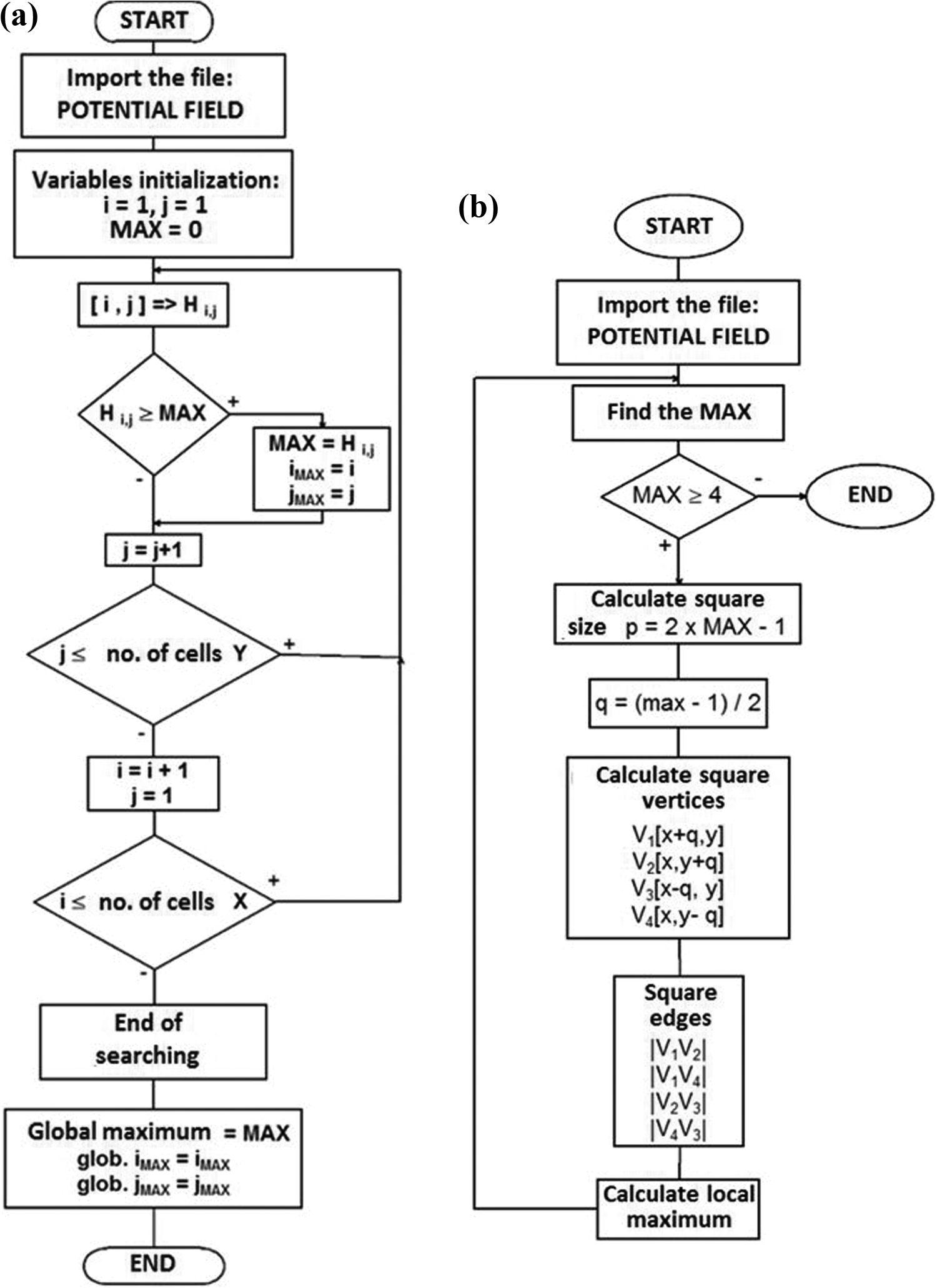
The algorithm for searching of global maximum cell (MAX) at the obstacle potential field (a) and the algorithm for identification of the first square (b).
The position and size for the first one as well as for all other inscribed squares must be defined. Location of the first square is defined by its center point identical with the global maximum cell (coordinates i MAX and j MAX).
Square dimensions are determined by the equation

The variable p is the diagonal length of the largest possible inscribed square, which is directly dependent on the MAX value. To determine the coordinates of the four square vertices V 1, V 2, V 3, and V 4, it is necessary to calculate the value of the variable q.
The variable q represents the distance between the cell MAX and each square vertex Vi
(i = 1–4) and it is determined by the equation

Then, the first square (cell MAX with coordinates [i MAX, j MAX]) can be defined by the four formulas. Each formula defines one square vertex (V 1, V 2, V 3, and V 4)


The same method is used for generation of any other inscribed squares.
The first square is delimited by four linear segments |V 1 V 2 |, |V 1 V 4 |, |V 2 V 3 |, and |V 4 V 3 | (see Figures 5(b), 6, and equations (3) –(6)). Equations (1) and (2) will ensure that the square vertex or edge does not collide with the map border.

Principle of map transformation—Steps 1–4: (a) Obstacle potential field generated by the main software “Mobilny Robot v1.0” and imported to the second software and (b) searching of global MAX and the principle of first square creation.
Construction of all remaining squares
In search of the next set of squares, we must find all local maxima cells located in the border area of the previous square (Figure 7). If we look at each square edge and sequentially write down the value of individual cells Hi ,j in a row, we will obtain a graph as the one shown in Figure 8. Each local maximum will be identified as a center of next set of squares (Figure 9(a)). This process will be repeated until the whole space will be filled with squares (Figure 9(b)) larger than the safety distance between the robot and the nearest obstacle defined in the setup phase (in this case four units of distance).

Principle of map transformation—Steps 5–7: (a) searching for all local maxima on the square edges and (b) generation of the next set of squares based on these local maxima.
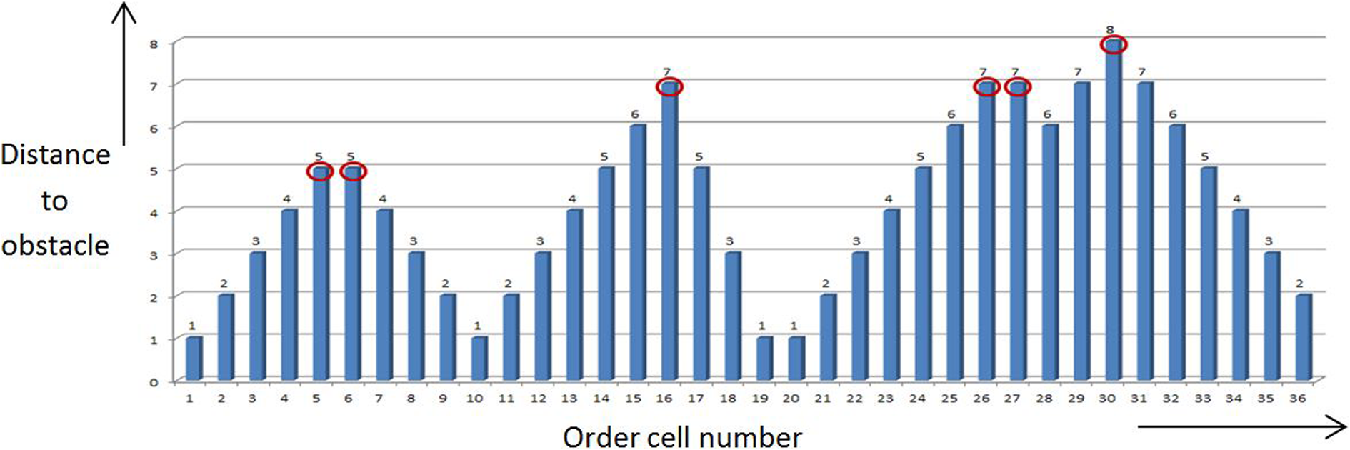
Searching for local maxima cells around the square border lines.

Finding of the next set of squares and identification of the second set of local maxima cells (a) as well as all other squares—process completed (b).
Topological map construction
The last step of the whole transformational process is actually the final topological map construction. The map construction is based on connecting the individual local maxima in the correct order (connection of the neighboring square centers by linear segments). The tracking always starts at the point designated as the global maximum (Figure 10). The final net of linear segments will create the topological map.

The final form of squares generated with the topological map—black lines.
Simulation results
Three examples will be described in the following section to demonstrate the proposed method of map-type transformation process for different levels of map size and complexity, as is shown in Figures 11 to 14. The first example demonstrates the principle of the proposed method in more detail and it is used to explain the individual steps of transformation process as well as the analysis of the results. The second example demonstrates the transformation of simple metric map, while the third one shows the transformation of a map with greater dimensions.

Example number 1—Metric map in the form of the occupancy grid (a) and the obstacles potential field (b) generated by the first simulation software “Mobilny Robot v1.0”.

The final form of the topological map generated by our second software “Transformacia” (a) and idea about the data filtration (b).

Example number 2—simple metric map transformation into the topological map (from left upper corner to right bottom corner): Step 1: map in metric form; Step 2: generated obstacles potential field; Step 3: localization of global MAX; Step 4: first square; Step 5: all other squares; and Step 6: final topological map.

Example number 3—processing steps of larger metric map transformation into the topological map (from left upper corner to right down corner): Step 1: map in metric form; Step 2: generated obstacles potential field; Step 3: localization of global MAX; Step 4: first square; Step 5: all other squares; and Step 6: final topological map.
Example number 1
At the beginning (Figure 11), the outputs from first simulation software (“Mobilny Robot v1.0”) are shown in the form of the occupancy grid and the obstacle potential field generated for a map with the cells of the size 40 × 40. These outputs were imported to the second simulation software (“Transformacia”), where the transformation process of the metric map into the topological map was done (Figure 12).
This algorithm leads to creation of quite a high number of points (square centers) and not all of them are really important for us (Figure 12(a)). Some of the points are too close to each other or they are placed in one line without any change in direction. This situation can be solved by filtration, where we will erase all useless points. An example of filtration process is shown in Figure 12(b). The implementation of this step into the simulation software is just under way.
Example number 2
This test demonstrates the transformation process of a simple metric map (Figure 13(a)) with the same 40 × 40 cell dimensions. The shapes of obstacles are different and it contains only the border loop (no free standing obstacles are there). The process steps are shown in Figures 13 (from (b) to (e)) and the results are shown in Figure 13(f). The results correlate with our prediction quite well.
Example number 3
In case of a map with larger dimensions (80 × 110 cells) shown in Figure 14, we can see that the transformation process leads to generation of a higher number of points and more complex structure of the topological map (green lines). This topological structure needs adjusting by the upper mentioned filtration.
Conclusions
One of the basic tasks in mobile robotics is the path planning. Therefore, it is necessary to have a suitable internal representation of the robot workspace in order to effectively plan and execute navigation tasks. It is possible to choose from several kinds of representation—different kinds of metric and topological maps. Not all of them are suitable for any type of navigation. It can lead to the necessity of using a multilayer system. According to literature, 1,9,27,28 the topological map is a set of certain important elements (rooms, crossing, etc.) connected by linear segments. This structure reflects the typical organization of real indoor environments, where rooms and corridors define independent but connected local working spaces. By combining both paradigms, the approach presented here gains advantages from both worlds: accuracy/consistency and efficiency.
This article introduces the concept of data transformation between the metric and the topological maps. The main aim of this work was to design and verify algorithms suitable for generation of 2-D metric maps and their transformation into a topological form for mobile robot path planning. The results and benefits of this work can be summarized in the following points: Two separate software applications were designed to test the proposed algorithms. Our main software (“Mobilny Robot v1.0”) is based on metric representation of the mobile robot environment and it can simulate both, local as well as tactic level of global navigation. There has been proposed one possible solution of mobile robot deadlocking avoidance (deadlocking in a sub-space separated by narrow doors or corridors), by means of which the previously used method with three steps can be replaced by a “two-step” process. The map in the form of the obstacle potential field is the output of the main software and simultaneously it represents the input data for the second software called “Transformacia.” The transformation process is based on certain adjustments of the entry metric map (potential field) carried out by software “Transformacia” to form topological maps. The functionality of the proposed algorithms has been tested. The simulation results (presented in Figures 11 to 14) of our approach shows that in this way of transformation can be obtained topological maps useful for navigation of mobile robots in 2-D environment. The algorithm sometime finds also points which are not important for topological map creation process. These clusters of points could be reduced by proper filtering process. Mentioned data filtering and creation of a simpler map structure can significantly reduce the amount of data as well as hardware requirements for computational processing power. The fact that the mobile robot with application of designed multilayer map system can increase the navigation efficiency (by combining the both map types) for large and branched spaces is considered to be the most important one when it comes to practice. The topological map (output from the software “Transformacia”) can be used for a rough structural description of the whole building or zone and fast navigation of the mobile robot between separate subspaces, e.g. rooms. Contrary, the metric map (output from main simulation software called “Mobilny Robot v1.0”) can provide more detailed description of a specific room, or specific obstacle, which can subsequently lead to more precise robot navigation inside the room. This can result to fast and precise navigation of mobile robots for large maps.
Reliable implementation of data filtering, as well as integration of transformation algorithms to our main software, is set as the main objectives for our future research. These modifications will lead to completion of the designed multilayer map system and increase the capability of the whole system to generate and use both types of maps (the metric and topological maps). The system could be used for controlling a real robot in an indoor environment with higher efficiency. Topological maps would be useful for basic task of path planning through the rooms and corridors of a building, while the metric map better describes obstacle avoidance at a close distance. Further continuous enhancement and improvement of both software applications is under way.
Footnotes
Declaration of conflicting interests
The author(s) declared no potential conflicts of interest with respect to the research, authorship, and/or publication of this article.
Funding
The author(s) disclosed receipt of the following financial support for the research, authorship, and publication of this article: This work is partly supported by the project APVV-16-0283: Research and development of multi-criteria diagnosis of production machinery and equipment based on the implementation of artificial intelligence methods.