
Abstract
Rotary twin screw compressors are widely used because of their high efficiency and reliability. Their most common mode of operation is as oil-flooded machines when delivering air and gases at moderate pressures and flow rates. In order to achieve the best performance, it is essential to be able to predict the optimum amount of oil, required for the oil injection process, accurately. Analytical procedures for the design and performance estimation of twin screw compressors are well developed and widely available, but the determination of oil drag losses, in oil-flooded machines is only guesstimated. This paper describes a more detailed and accurate procedure for estimating oil drag loss, using a combined Couette-Poiseuille flow model and gives the results of studies on three sizes of machines operating over a range of pressure ratios and speeds. To this end, a parametric analysis has been developed based on a combined Couette-Poiseuille flow model and has been used to estimate the individual effects of pressure ratio, the various clearances and the oil viscosity on the total drag loss, for different sizes of the compressor. It can be seen from the results that at pressure ratios of up to 8.5, the drag loss due to the discharge axial clearance gap is nearly 2/3rd of the total, while nearly 1/3rd is due to the radial clearance. At normal operating speeds, the loss due to the interlobe clearance is insignificant, but as the pressure ratio increases, this rises more rapidly than that due to the axial and radial losses. The gain in the drag loss due to greater oil viscosity becomes more significant as the compressor size is increased. In larger machines, when clearance values are increased, the radial and axial elements of the drag loss are reduced more rapidly than that due to the interlobe loss.
Introduction
Approximately 15–20% of the world's generated electrical power is consumed in compressing air or gas, while rotary oil-lubricated compressors account for nearly 60% of the entire air compressor market. 1 According to the IMARC Group (International Market Analysis Research and Consulting), which is a leading market research company that provides market and business research intelligence across the globe, the demand for those of the twin screw type, is likely to increase at a Compound Annual Growth Rate of 5% from 2021 to 2026. 2 Thus, even small improvements in their efficiency can lead to a substantial reduction in carbon footprint. 3 This gives a strong incentive to compressor designers to further improve their product performance. Oil-flooded twin screw compressors are growing in popularity because of their higher efficiency and better reliability, than reciprocating and turbo compressors at power inputs, in the 7 kW–2 MW range. 4 Hence, in applications where air, gas and refrigeration compression processes are required to deliver the working fluid at pressures of up to approximately 15 bar, they are widely used.
Oil is injected into the compressor for three main reasons, namely: to cool the compressed gas, to seal the clearance gaps and to lubricate the rotors and bearings. Although the cooling effect of the injected oil gives them high isentropic efficiencies, the frictional losses arising from the bearings, shaft seals and oil drag can reduce the overall adiabatic efficiency, significantly, as indicated by the Sankey diagram shown in Figure 1.
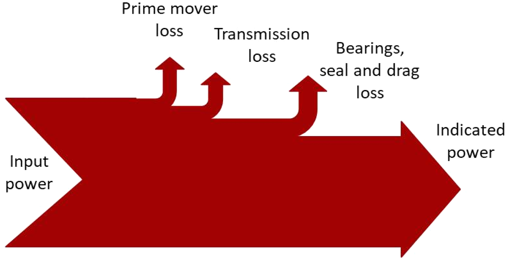
Sankey diagram of power loss.
The elements that contribute to power loss within the oil-injected, twin-screw air compressor are identified as the bearings, the shaft seal, oil drag and the drive system like the gear or belt drive mechanism 4 and numerous analytical, computational or numerical models are available to quantify the mechanical loss from each of them. Consequently, prediction models in the form of software tools for estimating and optimising their performance are widely used for their design.
The power loss in anti-friction bearings can be predicted with the use of popular models like those published by SKF, 5 and Harris and Kotzalas. 6 These models quantify the mechanical loss from bearings in two categories: load-independent, that is, that due to viscous effects arising because of lubrication, and load dependent due to the load acting on the bearings. The suitability of these models for cylindrical roller bearings which take radial load is experimentally studied by Tu 7 while Gradu 8 presented experimental measurements of power loss in tapered roller and angular contact ball bearings which take the axial load. These experimental measurements are compared with the predictions from SKF and Harris model and are presented in the study by Abdan et al. 4
A semi-analytical approach for the calculation of contact temperature between the shaft and shaft seal is presented by Frölich et al. 9 The authors proposed an empirical approach for the calculation of friction between the shaft and shaft seal. Experimental measurements of the influence of elastomeric lubricant combination on the operating performance of radial shaft seals are presented by Engelke et al. 10 with an algorithm to estimate the seal frictional loss. A method is proposed to calculate the radial shaft seal power loss, which is the combination of iterative and semi-analytical approaches. 11
The injection of oil can substantially change the thermal efficiency of the compressor and with the optimum choice of the oil viscosity, its injection position, temperature, and its uniform distribution within the compression chamber, the highest mass flow rate and compression efficiency can be achieved. The optimum level of these parameters depends on different operating conditions like tip speed and pressure ratio under which the compressor is running. However, an excess amount of oil can lead to undesirable frictional and momentum losses that lead to increased power consumption as presented by Deipenwisch and Kauder. 12 Gräßer et al. 13 presented an analytical model of the incompressible single-phase flow of auxiliary/lubricating fluid through the clearances in screw machines, expanders as well as compressors. The paper also presents the effect on power arising due to the frictional effects on the surface of the rotor due to drag arising in radial and axial clearances, however, drag arising in the interlobe clearance is not analysed. A comparison of the thermodynamic potential of clearance sealing and an opposing effect of frictional losses for liquid injected screw expanders is presented by Gräßer et al. 14 Even though the sealing of the radial clearance shows potential improvement in the thermodynamic performance, the frictional losses are negligible. However, the higher frictional losses are envisaged in axial clearance with marginal advantage in the performance as presented by Gräßer et al. 14 The relation between clearance sealing and frictional loss for liquid-flooded screw expanders in radial and axial clearances is shown in Gräßer et al. 15 An analysis presented in the study explains the considerable effect of radial and interlobe clearance on the thermodynamic performance and not so because of the axial clearance and blow hole. It also compares and recommends the preferential use of liquid-flooded and dry expanders for different operating speeds. To understand the effect of liquid injection temperature, the water and oil viscosities are varied with respect to temperature. With this analysis, it was observed that the variable water viscosity does not influence the hydraulic isentropic efficiencies. In contrast, the variable oil viscosity does influence the hydraulic isentropic efficiencies. A multiphase flow computational fluid dynamics simulation model for hydraulic loss mechanism in a screw compressor is presented by Vasuthevan et al. 16 The effect of the amount of oil injected and the rotation speed of the rotors on the hydraulic loss is estimated by simulating a 2D geometry of a rectangular contour. From their simulation analysis, the authors have concluded that the hydraulic loss increases both with the increase in tip speed and increase in the oil injection flow rate. However, the hydraulic loss due to the increase of oil flow rate is linear and proportional to the rate of oil flow, whereas that due to the increase in speed is proportional to the tip speed squared.
Basha et al. 17 conducted experimental studies to understand the effect of oil injection on twin-screw compressor performance. The size of the compressor studied was suitable for 22 kW power input. The parameters analysed during the experimentation were working fluid mass flow rate, the shaft speed, the injection position and the injected oil temperature. It is concluded from the study that at discharge pressures of 6.5 and 8.5 bar, the shaft power consumption increases with the increase in oil injection flow rate. This indicates that the increase in shaft power could be because of an increase in drag loss. Another experimental investigation was carried out by He et al. 18 on a 75 kW compressor with a male rotor size of 178.5 mm. The experiments were carried out to understand the effect of oil flow rate on volumetric efficiency, adiabatic efficiency and specific power consumption. Although the volumetric efficiency increases continuously with respect to oil injection flow rate, the specific power consumption remains almost the same for the same range of oil flow rate. Simultaneous analysis of these two effects with respect to oil flow rate indicates that the shaft power consumption increases with the increase in oil flow rate.
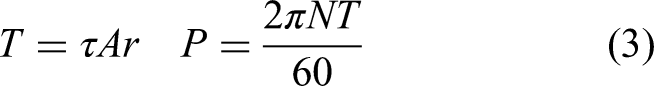
Although a number of computational studies are available, a simple analytical model for the prediction of oil drag loss in screw compressors is missing. The analytical approach has an advantage over the numerical approach in that the calculation times are much shorter and the physical laws, which can enable a better understanding of the flow processes, are clearly visible. The literature also lacks the quantification of drag loss through different clearance paths within the compression chamber. This is normally only guesstimated. In the case of the clearance gaps, oil is sheared between the clearance between the rotor tip-housing (radial clearance), rotor-rotor (interlobe clearance) and rotor end face-housing (discharge axial clearance), as shown in Figure 2. This causes drag, which contributes considerably to the power loss, and, therefore needs to be quantified in order to obtain a more accurate performance prediction and to optimise the design. This paper describes an analytical model for the prediction of the drag loss caused by the oil and also includes a parametric analysis of how it is affected by the compressor size, rotational speed, pressure ratio, oil viscosity and clearance size.
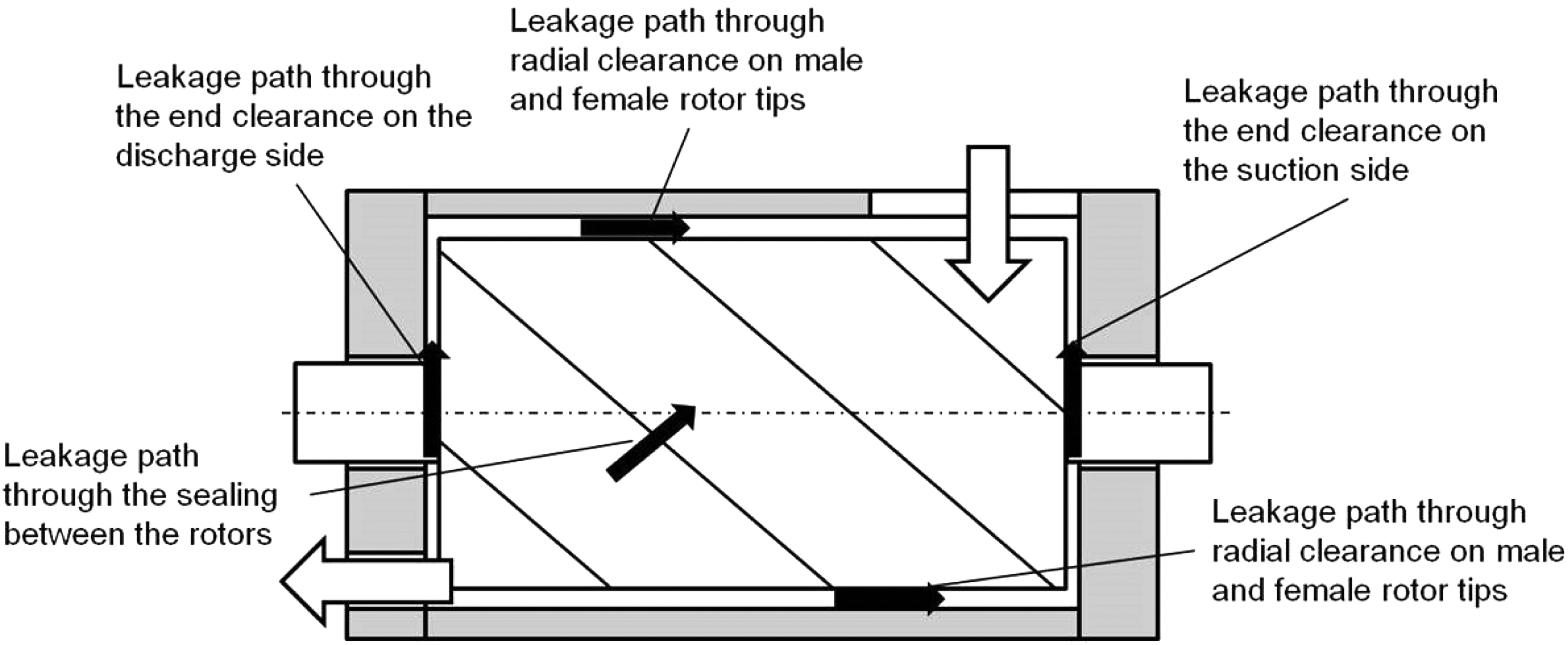
Leakage pathways through a screw compressor.
Modelling of drag loss
The cooling effect caused by the injection of oil within the compression chamber helps to achieve near isothermal compression, thereby reducing the power consumption. Another benefit realised from the injection of oil is the lubrication of the contact surfaces between the rotating elements including both the rotors and the bearings; and the rotating to stationary elements like the shaft seal. Even though the various clearance gaps are sealed with oil, as mentioned in the previous section, bringing another desirable effect, the injection of oil also creates a path for the shearing of the oil. Ultimately, these clearances, and leakage flows through them, cause the drag loss to increase the power consumption. In order to obtain high efficiencies, the clearance gaps must be as tight as possible. However, these are limited by machining and dimensional tolerances and the need for easy assembly.
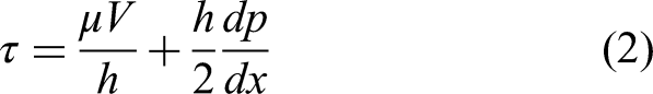
The oil flow through the clearance gaps is subject to drag forces, due both to inertia, and pressure-induced flow. The inertia force is created by the rotation of the rotors which is transferred to the adjacent layers of fluid. The differential pressure force generated by the progression of the rotors also acts on the fluid present in the clearance gaps. It acts in the opposite direction to that of the inertial force. Accordingly, a combined Couette-Poiseuille model has been used for modelling the oil flow through them and the resulting velocity profile for this is shown in Figure 3.
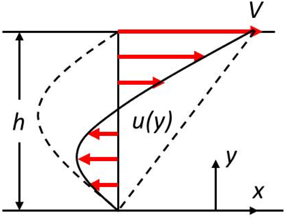
Couette-Poiseuille velocity profile.
The abscissa at the ordinate value of zero indicates a stationary boundary corresponding to either the housing or the relative rotor position, while the abscissa at the ordinate value ‘h’ indicates a moving rotor boundary. The dashed line with velocity values of zero at the top and bottom plane indicates the velocity profile for pressure-induced flow only, while the dashed linear line with velocity ‘V’ at the top plane indicates the velocity profile for drag flow. The resultant velocity profile for combined drag and pressure-induced flow is as shown by a continuous line indicated by u(y).
The analytical model developed was based on the following assumptions:
The planar representation of Couette-Poiseuille flow is considered The pressure gradient remains constant across all clearance gaps The flow is steady with the clearance gaps completely filled with oil The fluid is incompressible and Newtonian with constant properties There is no flow in the y and z direction
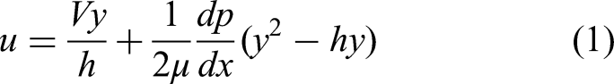
The supporting reason for the assumptions of planar representation for radial flow is that the curvature radius of the housing is three orders larger than the clearances maintained. Also, because of the relatively high viscosity of oil and characteristic lengths (clearances) of the order of micrometres, the flow will be always laminar in the clearance gaps. Using the conservation laws for mass and momentum with boundary conditions at the rotor tip and housing inner surfaces, the velocity profile takes the following form:
Representation of shear areas. (a) Shear area in radial clearance. (b) Shear area in axial clearance. (c) Shear area in interlobe clearance.
These equations were then used to calculate the drag losses in three sizes of oil-injected air compressors. These all had a 4/5 (male/female) rotor lobe combination and were designed for the following power inputs, namely: 15–30 kW (size 1), 37–55 kW (size 2), and 75–160 kW (size 3).
In these calculations of drag loss, the oil viscosity was assumed to be 9 cSt, while the oil density was assumed to be 850 kg/m3. The clearances considered for each size of the compressor are presented in Table 1.
Clearance values (mm) for size 1, size 2 and size 3 compressors.
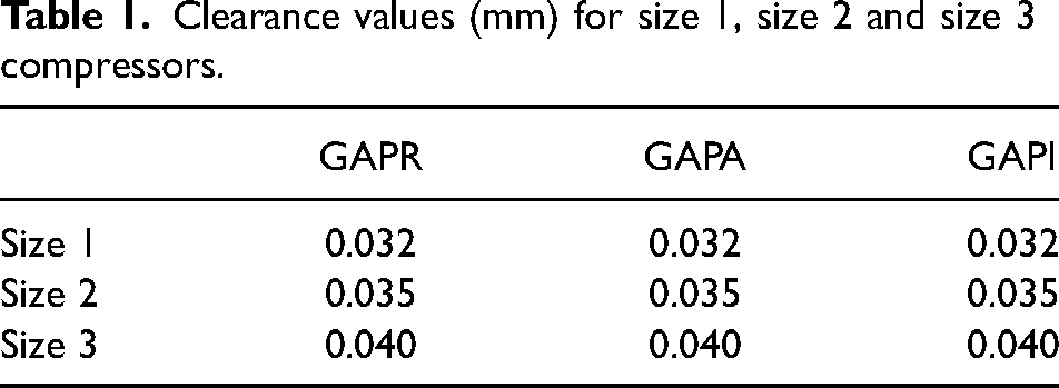
GAPR represents radial clearance gap, GAPA represents axial clearance gap while GAPI represents interlobe clearance gap.
Results and discussion
The results from the analytical model of drag loss are given for the three compressor sizes in this section. The effect of speed variation on each of the drag loss components is shown in Figure 5(a) to (c) for the size 1, 2 and 3 compressors, respectively, when operating at a pressure ratio of 8.5.
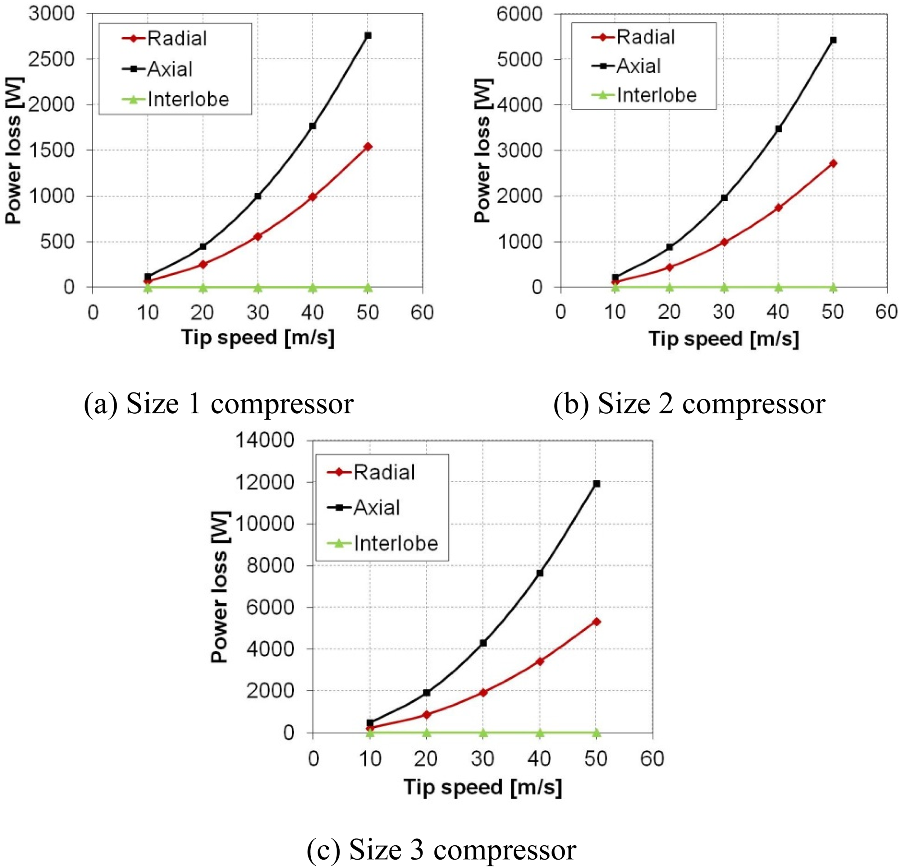
The effect of different sizes of the screw compressor on drag loss elements with respect to speed. (a) Size 1 compressor. (b) Size 2 compressor. (c) Size 3 compressor.
For all three compressors, the axial drag loss element contributes nearly 2/3rd of the total drag loss, radial drag loss element contributes to the remaining 1/3rd part while drag in the interlobe clearance is very low. Relatively high drag loss in the axial clearance on the discharge end of the compressor can be attributed to the fact that the shear area and pressure gradient are high as compared to the radial and interlobe elements of the drag loss. This is analogous to experimental observations that the axial gap on the discharge side of the compressor has the largest effect on the volumetric flow rate.
Parametric analysis
A parametric analysis was carried out to determine the effect of pressure ratio, oil viscosity and clearance values on each of the elements that make up the total drag loss.
Effect of pressure ratio on elements of drag loss
Losses from operation at pressure ratios (π) of 8.5, 10 and 12.5 were estimated for the size 2 compressor over a range of speeds. The effect is shown for each of the elements of the drag loss in Figure 6(a) to (c). As can be seen, the radial and axial elements of the drag loss increase non-linearly with speed, whereas the increase of the interlobe element with speed is linear.
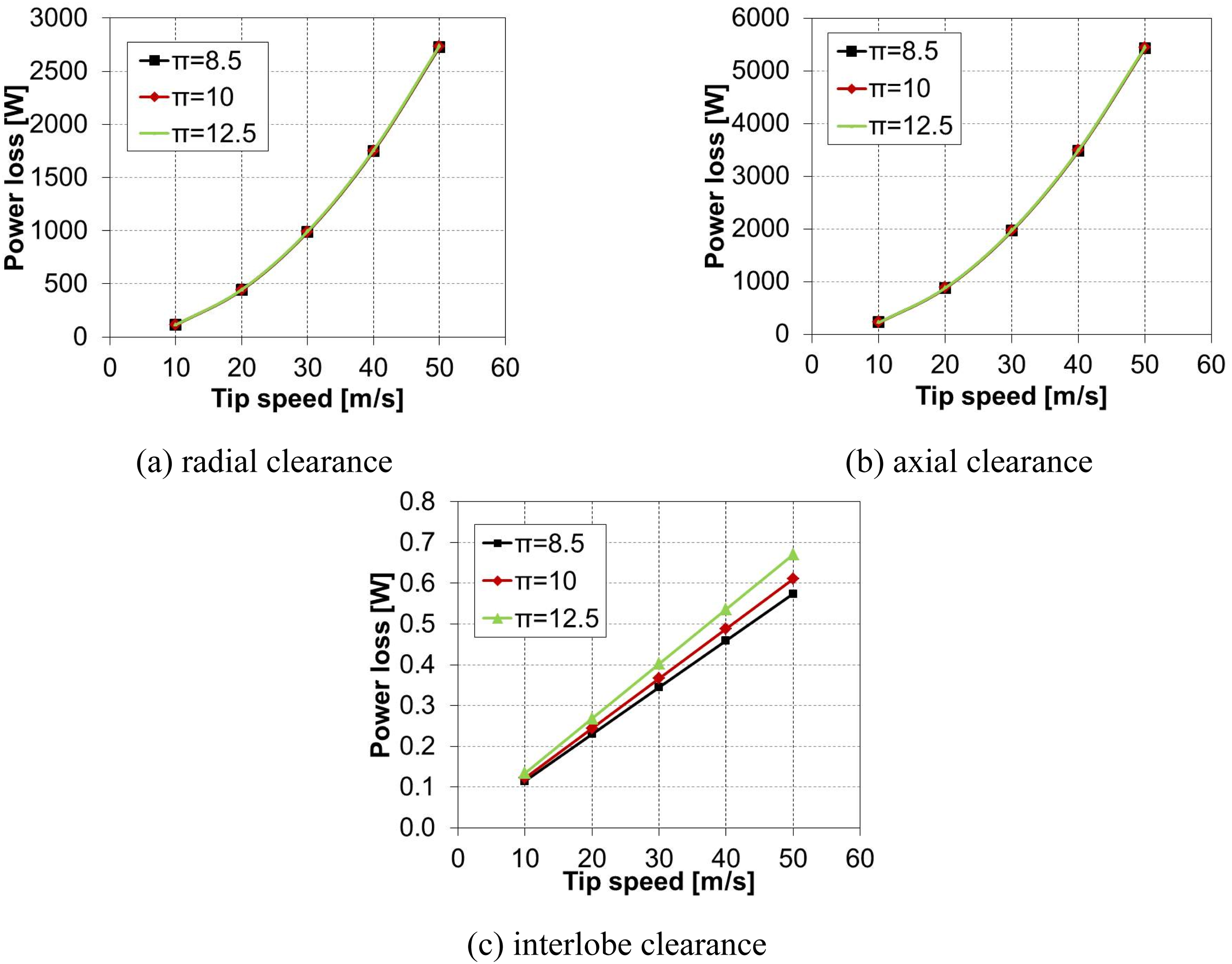
Effect of pressure ratio on drag loss with respect to speed for size 2 compressor. (a) Radial clearance. (b) Axial clearance. (c) Interlobe clearance.
It can also be seen that the effect of pressure ratio has a very marginal effect on the radial and axial elements of drag loss, resulting in a 0.1–2% rise in drag loss, for a change of pressure ratio from 8.5 to 12.5. However, for the same pressure ratio range, the interlobe element of drag loss shows an increase in drag loss of 6–14%.
An increase in compressor power with the increase in pressure ratio is the addition of adiabatic power and total loss due to bearings, oil drag, seal and windage. The relative contribution of the bearings in the power loss, with respect to the pressure ratio, is highest while that of the other elements is not so significant. 11
Effect of oil viscosity on total drag loss
More viscous oil generates more resistance to the flow and higher losses. The analysis confirms that the total drag loss increases at higher oil viscosity as shown in Figure 7. This agrees with real-life behaviour, but it can be seen that the percentage rise in drag loss is more significant for larger compressors.
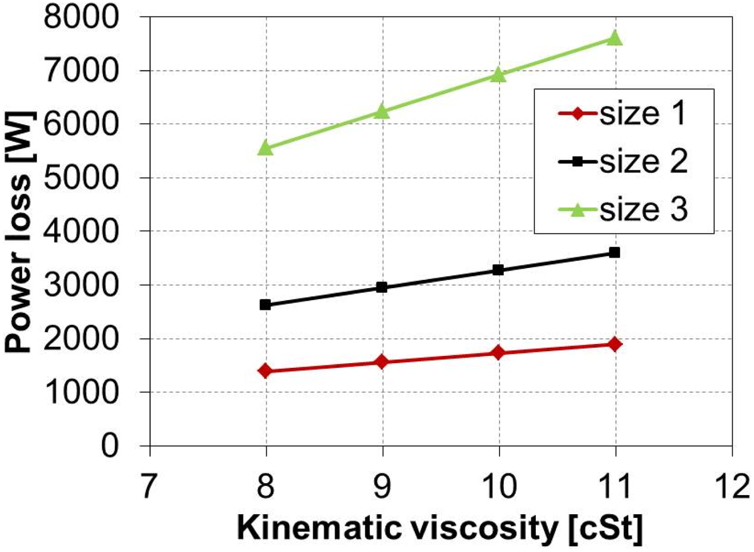
Effect of oil viscosity on drag loss for different size of compressors and π = 8.5.
Due to the selection of different clearance gaps for the different sizes of the compressor, the leakage areas available for shearing of oil are different. The same is observed in Figure 7 where the relatively larger leakage areas that are required for the bigger sizes of compressors result in higher losses.
Effect of different clearances on elements of drag loss
The effect of different clearances on the drag loss in the radial, axial and interlobe elements, for the size 2 compressor, is shown in Figure 8(a) to (c), respectively, when operating at a pressure ratio of 8.5. As can be seen, the change in clearance has more impact on the radial and axial elements of drag loss than on the interlobe element. Both, the radial and axial elements show a reduction in drag loss of almost 25% when the respective clearance is increased from 0.030 to 0.040 mm. However, the interlobe element of drag loss is reduced by only 10% when its clearance increases from 0.030 to 0.040 mm.
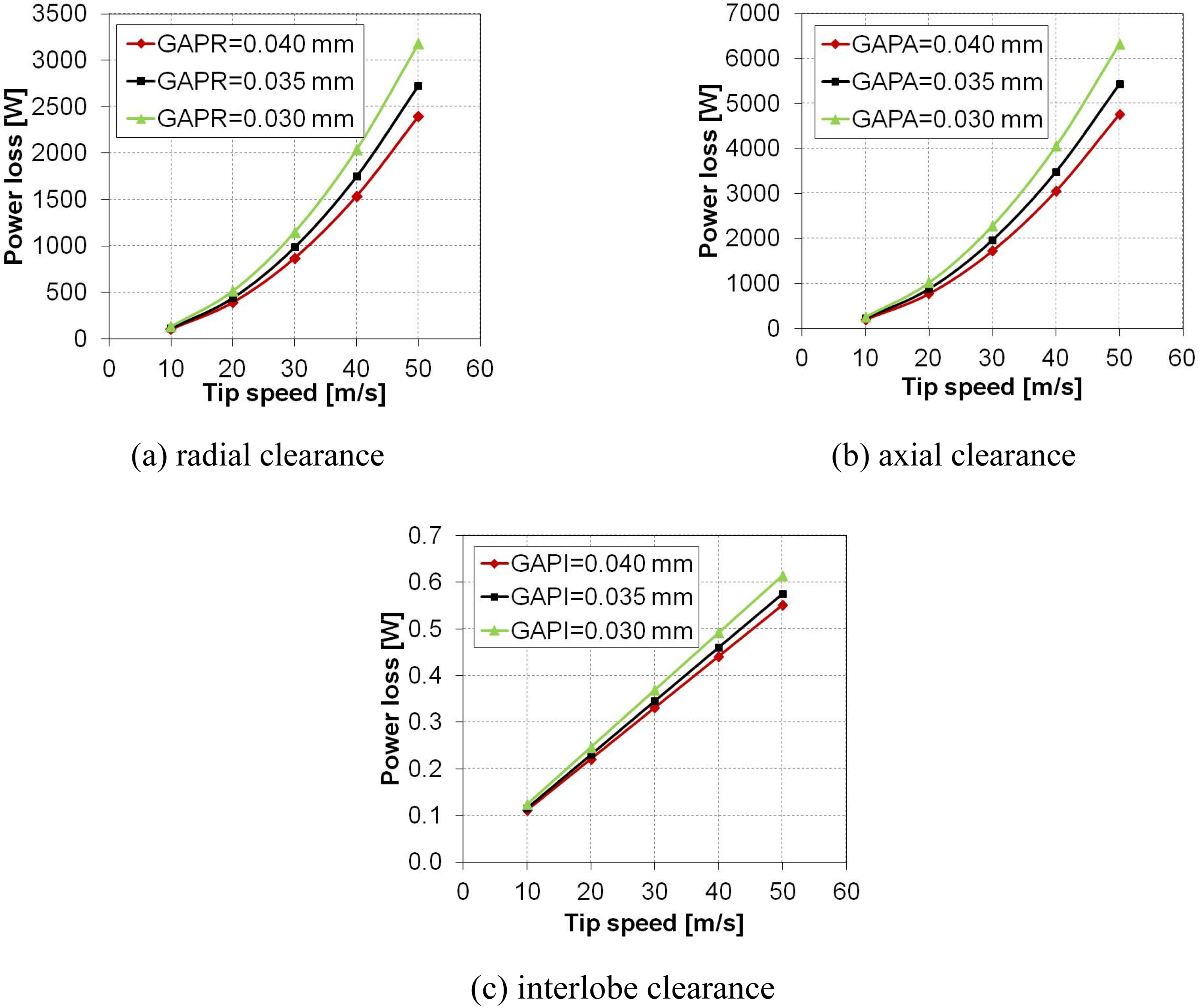
Effect of different clearances on drag loss at π = 8.5 with speed for size 2 compressor. (a) Radial clearance. (b) Axial clearance. (c) Interlobe clearance.
Conclusions
An analytical model has been developed to calculate the drag loss in an oil-flooded, twin-screw compressor using a combined Couette-Poiseuille model. The model proposed has been used to estimate the contribution of different elements of the drag loss for different size machines over a range of operating conditions. The study also includes a parametric analysis to understand the effect of pressure ratio, tip speed, oil viscosity and clearance on drag loss. The following conclusions can be drawn from this study:
Drag loss in the discharge axial clearance gap is nearly 2/3rd of the total drag loss, and nearly 1/3rd in the radial clearance while drag loss due to the interlobe clearance is very low. As the pressure ratio increases, the percentage increase in the interlobe element of the drag loss is higher than in the other two elements. As the oil viscosity is increased, the total drag loss in larger compressors increases more rapidly than in smaller compressors. As the clearances are increased, the radial and axial elements of the drag loss are more significantly reduced than the interlobe element of the drag loss.
Footnotes
Acknowledgements
We gratefully thank Kirloskar Pneumatic Company Limited, Pune, India for sponsorship and Prof. Stosic, Prof. Kovacevic and Prof. Smith of City, University of London for their continued support and guidance.
Declaration of conflicting interests
The authors declared no potential conflicts of interest with respect to the research, authorship, and/or publication of this article.
Funding
The authors disclosed receipt of the following financial support for the research, authorship, and/or publication of this article: This research was supported from Kirloskar Pneumatic Company Limited, Pune, India.