
Abstract
Industry 4.0 aims to make collaborative robotics accessible and effective inside factories. Human–robot interaction is enhanced by means of advanced perception systems which allow a flexible and reliable production. We are one of the contenders of a challenge with the intent of improve cooperation in industry. Within this competition, we developed a novel visual servoing system, based on a machine learning technique, for the automation of the winding of copper wire during the production of electric motors. Image-based visual servoing systems are often limited by the speed of the image processing module that runs at a frequency on the order of magnitude lower with respect to the robot control speed. In this article, a solution to this problem is proposed: the visual servoing function is synthesized using the Gaussian mixture model (GMM) machine learning system, which guarantees an extremely fast response. Issues related to data size reduction and collection of the data set needed to properly train the learner are discussed, and the performance of the proposed method is compared against the standard visual servoing algorithm used for training the GMM. The system has been developed and tested for a path following application on an aluminium bar to simulate the real stator teeth of a generic electric motor. Experimental results demonstrate that the proposed method is able to reproduce the visual servoing function with a minimal error while guaranteeing extremely high working frequency.
Keywords
Introduction
Robots currently operating in production plants are not equipped with perception systems (except for the mandatory safety systems). However, perception in industry is a very active research field, as it is an enabling technology for developing human–robot interaction in production plants, and more flexible production processes, leading to large-scale customization, which is one of the frontiers of the Industry 4.0 revolution.
The concept of Industry 4.0 revolution is already well established in the main technological advanced countries. Europe is moving in this direction by spending many efforts and resources with high priority. In particular, according to the pillars in which Industry 4.0 is based, 1 an objective is the promotion of the connection and cooperation between research community and industries, also by means of open projects. This work is part of one of these projects where our research activity is merged with the know-how of the industrial partners in order to solve real industrial problems.
The starting point is the electric engine manufacturing: this production needs a metal wire to be wrapped around a metal component, namely the stator. Automating the wrapping process has a strong technological and economical impact, since it is currently completed by humans for slots of up to 100,000 pieces. Indeed, this is a time-consuming task, and even small deviations from the optimal wrapping process have negative effects on the performance of the engine produced. In this work, we propose an early implementation of an advanced visual servoing based on machine learning for automatically deploying the copper wire around each stator tooth by means of a lightweight collaborative robot provided by a custom tool and just a single monocular camera as perception device. We simplify the problem by simulating the small space between two engine teeth with the U junction slot in a standard aluminium profile. They are very similar in shape, and we can extend experiments to engines of larger dimensions using a longer bar, instead of developing an ad hoc engine for our tests. Moreover, slots in aluminium bars are not as narrow as tooth gaps, giving us the perfect early stage setup.
Visual servoing is widely used while manipulating or inspecting objects. This tool can be decoupled into two modules: one is in charge of perception and the other handles robot motion. The main advantage is represented by the continuous feedback provided by the sensor exploited for driving the robot motion, following a control law which relates robot kinematics and object tracking. This mechanism provides several advantages: first, it offers the capability of recovering from motion drifts and inaccurate motion planning (provided by the feedback structure); second, the measurements provided by the sensor have increased accuracy as long as the robot gets closer to the object – this happens when the sensor is mounted on the robotic arm, which is very often the case when dealing with visual servoing. However, the direct feedback of the vision sensor on the robot motion often becomes a weak spot of visual servoing systems. Image processing algorithms are often computationally intensive, and they are the main cause of latency in the system, which limits the refresh rate of the commands provided to the robot. Such phenomena are particularly undesirable for robots, which are inherently real-time systems. To better understand the difference in the time scales of perception and action, consider that fast computer vision algorithms analysing standard-size images could have running frequency lower than 10 Hz, while research and industrial robots can accept commands with a frequency significantly higher than 100 Hz. As the image processing block required by visual servoing is usually the bottleneck of this kind of systems, optimization on this side leads to strong benefits.
We developed a visual servoed path following system in order to scan the slot of the extrusion bar for simulating the wire deployment in the real stator teeth. We took care that the tool pin was kept continuously inserted in the gap at a fixed height and orientation, and avoid collisions ensuring an high control rate.
This work tackles the latency introduced by the sensory system by proposing an alternative method for driving the robot motion starting from images. Several possible choices are available to decrease the processing time: the most straightforward choice is code optimization, which can lead to sensible improvements, but it is not the best choice if the required improvement is by an order of magnitude. A second option is graphics processing unit (GPU) processing, which can provide huge improvements by one or more orders of magnitude, but requires dedicated hardware and software; more importantly, the speed-up strongly depends on the algorithm structure and which portions can be parallelized. A third option is hardware implementation, which, however, suffers from strong flows, the main ones being low flexibility and a strong hardware design effort, with high costs.
Our innovative approach overcomes the bottleneck of the general class of image-based visual servoing (IBVS) systems using a different technique. Since the time scales of image processing and robot control in an IBVS system typically differ for an order of magnitude, the solution proposed to reduce the processing time is to substitute the image processing module by learning the visual servoing function. A machine learning algorithm is trained using a small portion of the image and the corresponding robot control command, to be considered, respectively, as input and output data in the testing phase. The model chosen in this study is a Gaussian mixture model (GMM). After training, the model can be used in place of the IBVS system: this novel way of exploiting machine learning for synthesizing an IBVS system leads to a strong decrease of the processing time, bringing the working frequency of the visual servoing system close to the typical values of robotic systems.
The remainder of this article is organized as follows. In ‘State of the art’ section, related work on visual servoing and machine learning for robot control is discussed; details on our approach will be given in ‘System’ section, and the results of our tests, both in terms of precision and speed-up, will be detailed in ‘Experiments and results’ section. Final remarks and conclusions are reported in ‘Conclusions’ section.
State of the art
In the context of IBVS, the literature shows different attempts to avoid image processing and feature tracking for increasing the processing speed. Direct visual servoing approaches addressed this issue by considering the image as a whole: the task is defined as a minimization problem between the current and the desired image. 2 An interesting alternative is represented by the introduction of new visual features based on luminance. 3 The approach called photometric visual servoing 4 is mainly based on the simple extraction of the image gradient, consequently removing any other necessity for image processing. The main drawbacks of photometric visual servoing are the strong non-linearities in the system dynamics: to address this problem, the use of photometric moments has been introduced. Moments capture the characteristics of an unknown distribution. They have been applied to image intensity in order to obtain a large convergence domain 5 and extended including spatial weights to contrast the disappearance of portions of the scene. 6 A second way to increase the convergence domain of the photometric visual servoing is to represent each intensity pixel as a Gaussian distribution extending its influence to the neighborhood. 7 The goal is to minimize the difference between the desired Gaussian mixture and the current one. Photometric and photometric moments are geometrical interpretations of a more general class of methods called kernel-based visual servoing 8 in which spatial sampling functions called ‘kernels’ are used to find so-called abstract visual features.
Another recent technique exploits mutual information, 9 defined as the quantity of information shared by two signals (images in our case) to align two images to be robust to appearance variations. On the contrary, our approach does not properly belong to the class of direct visual servoing. Indeed, it relies on a machine learning algorithm to model the control law implemented by a ‘traditional’ feature-based approach. The idea is very similar to the one proposed by Hafez et al., 10 where the feature tracking step has been removed by modelling image features with a Gaussian mixture. We expanded this concept by removing both image processing and feature tracking from the loop, moving to a completely different direction with respect to other works aiming at the same objective.
On the other hand, Hafez et al.’s work 10 is not the only attempt of using machine learning for improving robot motion control. Reinforcement learning (RL) based on neural networks (NNs) has been used to enhance visual servoing for a manipulator in the case of visibility problems, incorrect calibration parameters, white noise and modelling errors 11 or for reducing the required amount of information in tasks, such as reaching and grasping. 12 In a different paper, 13 an adaptive distributed fuzzy proportional–derivative (PD) controller served as a map between the image error vector and the joint velocities of the robot. This avoided the need to compute both pseudo-inverse robot Jacobian and inverse interaction matrix, yet maintaining the image processing phase. With Sadeghzadeh et al., 14 again the available information is limited and the system is able to learn online new tasks by means of fuzzy NNs and RL.
In a very recent work, 15 deep learning has been used to learn hand–eye coordination for grasping purposes. The approach consists of two parts: one predicts the probability of success of a certain command from the camera image and the other functions as the continuous servoing. This approach substantially removes any kind of image process and feature tracking using a huge amount of data (more than 800,000 grasp attempts) for training the deep convolutional NN driving the algorithm. Nevertheless, the actual aim of this work was a task generalization more than a computational redaction. Indeed, no analysis has been performed regarding control rate or responsiveness of the system.
With respect to the majority of these works, our working setup is restricted and we already know the essential information about the environment in advance. Our key contribution consists in having the entire visual servoing process replaced by a probabilistic framework for improving the robot control rate and with only a limited number of examples coming from a traditional visual servoing at disposal to train the model acting as control law.
System
As outlined in ‘Introduction’ section, this study aims at creating a visual servoing system based on machine learning – this offers the major advantage of a much faster processing and increased reactivity while keeping precision at almost the same level of a traditional visual servoing used for training the system.
Our system is divided into two modules: an offline phase and an online phase. The offline phase exploits an IBVS system running on a custom data set, in which the cavity in the middle of an extrusion bar is visible, as shown in Figure 1. The robot task is to follow the cavity. Such task requires a high precision, since the bar cavity is narrow.
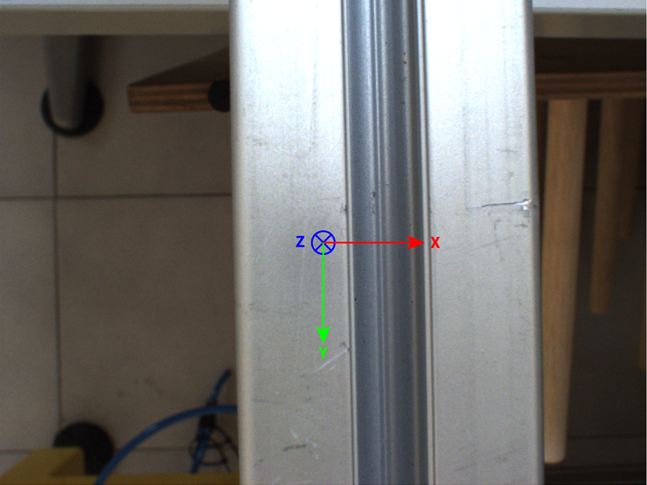
Image of the bar taken from the camera mounted on the robot tool center point (TCP). We consider as the camera frame the one fixed in the center of the image, with the z-axis coincident with the optical axis of the camera and the x- and y-axis parallel to the horizontal direction and vertical direction of the view, respectively.
We recorded several runs with the robot following the cavity driven by IBVS: acquired images and resulting velocities were used to train the machine learning framework acting as visual servoing. A GMM has been used for data representation, while Gaussian mixture regression (GMR) has been exploited for computing the output during the online phase. We selected such framework mainly, because Gaussian mixtures generally need a smaller number of examples with respect to other techniques in order to obtain significant results. Moreover, the regression process is very fast, which is crucial to achieve a high frame rate in the whole process and therefore a higher robot control rate.
Visual servoing
We considered the problem of scanning a gap on a straight object with a camera mounted on the robot end-effector. The control of the robot has been performed through a visual servoing approach with an eye-in-hand configuration, 16,17 assuming the camera frame defined as in Figure 1.
The desired pose of the camera with respect to the bar is with the z-axis perpendicular to its direction, at a fixed distance and the scanning direction parallel to the y-axis, going towards the negative values. In this configuration, the x-axis will be always perpendicular to the bar direction. These choices do not affect the generality of the system.
We define, with

The main purpose of visual servoing is to provide a closed-loop control law to drive the camera from ξ to a desired pose ξ* in such a way, the image feature parameters assume the desired values

where

where θ denotes the angle with the x-axis, while ρ defines the distance of the line from the origin. This convention provides a subsequent parametrization

where A, B, C and D are the coefficients of a 3D plane containing the line. In order to ensure the exponential decoupled decreasing of the positioning error

where λ is a proportional gain involved in the exponential convergence of

(a) Source image. (b) Edges image. (c) Clusters of lines (red, blue) and the final selected lines (green). (d) ViSP moving edge tracker result. ViSP: visual servoing platform.
Since we have a contour following problem, the camera motion must be controlled in order to follow the desired path, which should go along the two lines. Our main goal is to maintain the camera aligned with the gap and move along the bar for its whole length with respect to the camera’s y-axis, and therefore, the y velocity component Vy is controlled depending on the features error

where

with
Actual values of the visual feature parameters
The Hough line transform
22
has been employed in order to retrieve all the line parameters
The tracker selected for following the cavity edges is a moving-edge line tracker, 25 which demonstrated good performance for the problem at hand; moreover, a fast and reliable implementation can be found in ViSP.
GMM and GMR
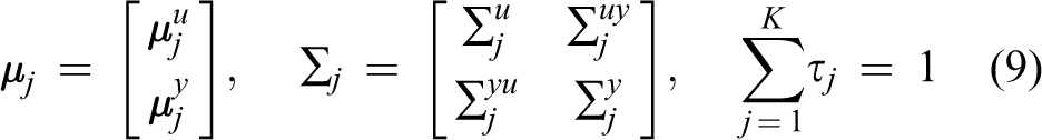
The GMM is a parametric probability density function represented as a weighted sum of Gaussian component densities, which best fit the training data set. Naming K the number of Gaussian components with which the problem must be approximated, the model can be characterized by the list of parameters

where:
All the parameters
Considering a single training data

where

The EM algorithm is applicable only if K is known a priori. A method to estimate K is to use the Bayesian information criterion, 26 but we used an empirical method, based on experimental observations. Indeed, few components cannot completely describe the system, while by selecting many components, the model becomes much complex introducing redundant information and then giving a null weight to some prior.
GMR estimates output data by specifying the desired input. Therefore, input and output data together represent a possible occurrence of training data set, where the input is selected by the user and the output is an estimation calculated using GMM. 27 In particular, a single data element can be rewritten as

Gaussian model parameters are partitioned in a similar way
Then, the regression function assumes the form

with

Offline phase
This step aims to acquire a valid data set, suitable to train a GMM, as described in ‘GMM and GMR’ section. In particular, several scanning trials are performed with the visual servoing approach of ‘Visual servoing’ section, starting from different initial positions and with small external perturbations in order to make the system more robust. Visual servoing needs images with a high resolution in order to extract good features to be tracked, with a consequent frame rate limitation.
The dimension of the input data is a crucial parameter for any machine learning algorithm; in particular, high-dimensional input vectors stimulate the curse of dimensionality, leading to poor performance and need for huge training data sets. To reduce the number of inputs, one single image row (called patch) is provided to the GMM: this is feasible for our problem, as the input images are invariant along the y-axis.
During each trial, for each control loop, namely for each frame

Each patch has a gray level distribution related to the bar pose with respect to the camera, that is, all the information that needed to compute the camera displacement can be extracted from the image as IBVS does. IBVS: image-based visual servoing.
A data set composed of many couples
Online phase
In the online phase, the camera resolution has been physically reduced to an area which correspond to the patch extracted during the offline step. For each frame, the relative camera velocity has been estimated through GMR by exploiting the GMM trained during the offline phase. In this way, it is possible to emulate the visual servoing control law with a statistical model with the advantage of eliminating all the image processing on high-resolution images. This corresponded a reduction in the processing time, and the consequent possibility to increase the camera frame rate and the overall control rate.
Experiments and results
Experimental setup
We tested our system in a real environment reproducing an industrial setup (Figure 4) composed by a lightweight collaborative 6 degrees of freedom (DOFs) manipulator (Universal Robots UR10) equipped with a fully calibrated camera PointGrey Grasshopper 3 with the following specifications:
Model: GS3-U3-28S4C-C.
Sensor: Sony ICX687 CCD, 1/1.8′′, 3.69 μm.
Megapixel: 2.8MP.
Interface: USB3.
Resolution max: 1928 × 1448.
Frame rate: 26 fps at full res.
Optic: Computar 8 mm 1:1.4 2/3.

System used for simulations.
The aluminium bar has been fixed horizontally to the robot support to represent the engine tooth to be scanned, a gap of 1.2 cm between the borders, as shown in Figure 2(a). All the developed code has been written in C++ within the ROS framework, exploiting the tools provided by the open source libraries OpenCV
28,29
and ViSP. Simulations have been launched and monitored in a personal computer (PC) with the following specifications:
Processor: Intel Xeon CPU E3R25 at 3.10 GHz × 4.
OS: Ubuntu 14.04 (x86-64).
RAM: 4GB.
Graphics: NVIDIA GT218.
Results
A training data set has been built by acquiring several scans of the bar cavity based on the IBVS framework presented in ‘Visual servoing’ section. The camera employed has a frame rate of 26 fps at full resolution, which could not be sufficient for applications requiring high responsiveness. For this reason, we reduced the resolution of the images in input to the IBVS system. A size of 500 × 400 at 55 fps has been selected as a good trade-off between frame rate and feature quality for detection and tracking. Performance decreased without a significant increase in the frame rate by further reducing the resolution.
The tune-up of the IBVS system consisted in the definition of the desired lines configuration

that is, we assumed the lines as vertical; according to the camera parameters, these values correspond to a height of the camera from the bar of about 15 cm. The parameters regulating the camera motion have been selected with empirical observations after some trials, resulting as
Several trials starting from different initial positions of the camera were recorded. The velocity has been computed using the IBVS control law, while the patches have been derived from a subsampling operation on the central pixel row, leading to an image of size 500 × 1.
Patch selection is a critical step of this approach: it must maximize the information contained while minimizing the size for both reducing the dimensionality of the problem and increasing the frame rate during the online phase. In particular, we discarded 100 pixels from both sides of the image, since they contained background; from the remaining 300 elements, only one over three pixels has been selected as training data, obtaining a 100 × 1 patch as shown in Figure 3. Our data set was composed of approximately N ≃ 10,000 samples, where about 4000 samples came from scanning started from position aligned with the bar or with small perturbations, while 3000 samples were extracted from left misalignments, and the last 3000 were obtained from right misalignments. As already claimed, in this work, we supposed a correct initial height of the camera, and therefore, only lateral displacement has been considered for the tests. Finally, we trained a GMM composed of K = 4 Gaussian components. The number of components has been selected empirically by comparing results from models created with the same input data, but with increasing K values.
In the testing phase, the resolution of the camera has been reduced to the minimum size height allowed by the camera, that is, 500 × 2. A 100 × 1 patch has then been obtained by selecting the first row and subsampling it. Using these settings, it was possible to reach a frame rate of 94 fps, the maximum achievable by the camera, according to its datasheet. This represents an improvement of about 41.5% with respect to the framerate used during the offline phase (Figure 5).

Image resolution of the camera has a dominant impact on the frame rate. Our method allows to perform a visual servoing task with a single row of pixels at a frame rate not achievable with standard image processing techniques.
The real visual servoing was compared to our learning-based method in order to verify the performance in terms of path followed, velocity set, precision and control rate improvements. In Figure 6, position and rotation of the camera have been monitored over the samples for the two considered systems (real visual servoing and GMM-based). The learning-based system was able to follow the gap in the aluminium bar, the recorded poses differed from the ones set by the traditional visual servoing system only for a small tolerance. This result is crucial, as it demonstrates that a learning engine is able to emulate the entire visual servoing behaviour when properly trained.
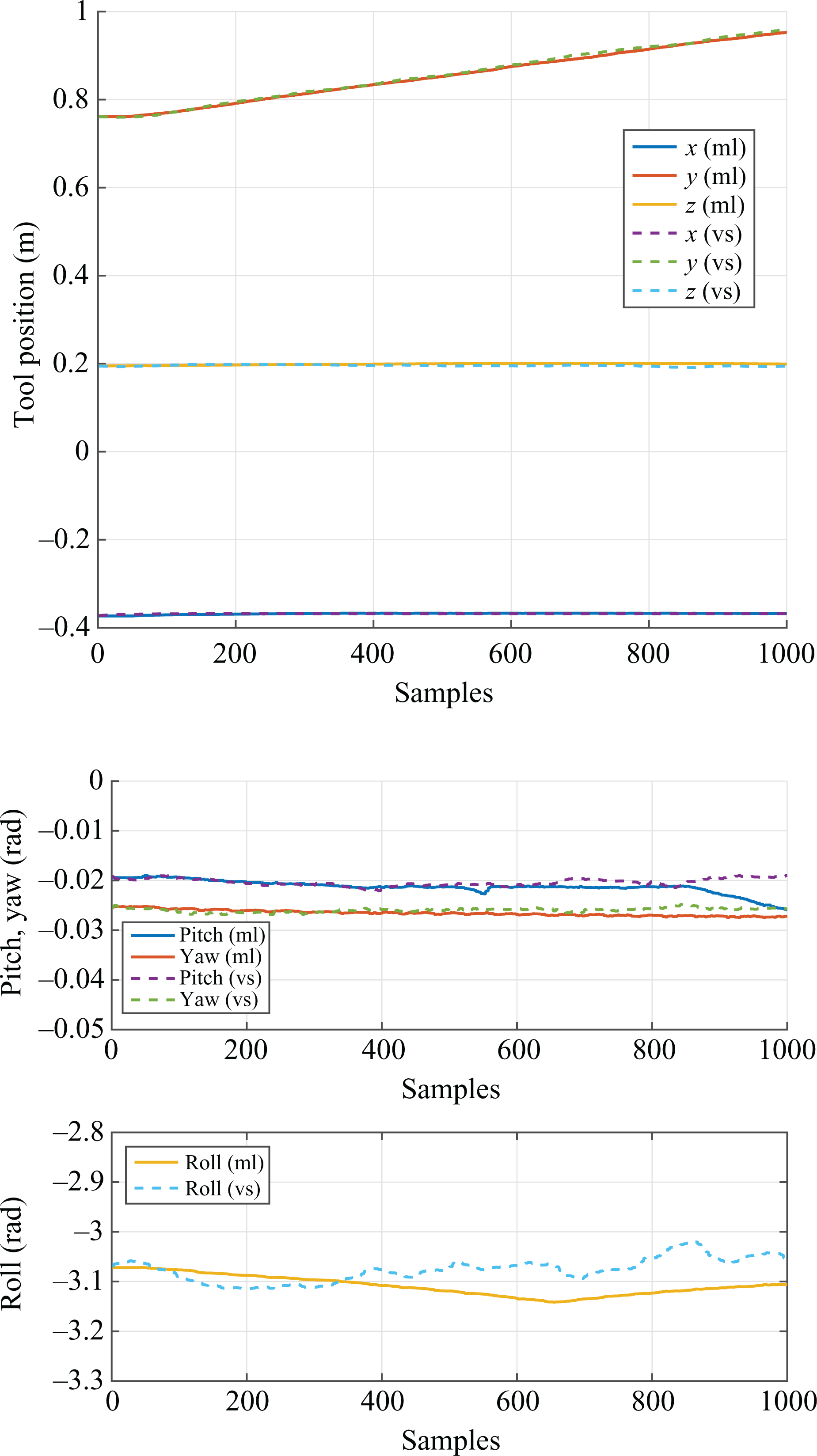
Camera path comparison, in terms of position and rotation.
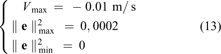
In order to better evaluate the performance of our system, commanded velocity has been monitored within the same experiment, and plotted in Figure 7. Oscillating behaviours in the y component of the IBVS are projected into each component of the learning-based system, and are caused by the use of a distribution obtain through a sum of Gaussians. Indeed, the oscillations coming from the forward velocity control have been modelled as input data without a clear separation of the single velocity components, leading to a correlation between the parts and a consequent propagation of oscillations. Moreover, GMM performs an intrinsic smoothing of the data, resulting in low velocity values. In particular, for the forward velocity vy, we reached an average value of about −0.005 m/s starting from a desired value of −0.01 m/s. It should be observed that during the 25 s (Figure 7) of simulation, the difference in the number of samples due to the increased frame rate allows the learning system to perform the velocity control more times with respect to the standard IBVS, with a consequent improvement in responsiveness.
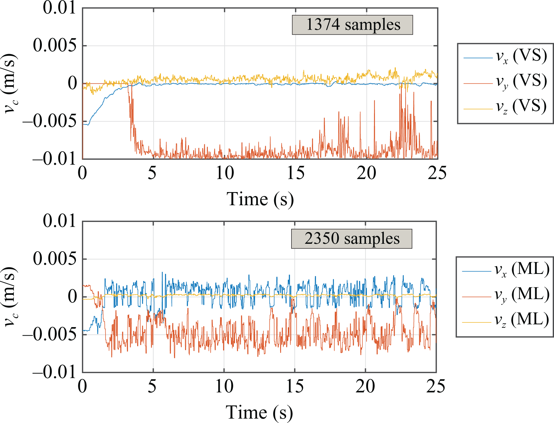
Velocity command output comparison. Only linear velocity is here reported as more informative data.
The slight degradation of the control performance caused by velocity oscillations is counterbalanced by the higher frame rate. For IBVS, the average processing time is of about 13.6 ms, which allows a maximum throughput rate of about 73 fps without frame loss. Therefore, even if a powerful camera is used, the effective throughput of the control law would be limited by the constraint given by the processing time. Using the learning-based control, on the other hand, leads to the average processing time of about 0.17 ms, 100 times lower than the previous case (Figure 8). The maximum allowed theoretical throughput would be of about 5882 fps with a dramatic performance improvement (Figure 9). The proposed solution offers a good trade-off between accuracy and responsiveness.

Time performances comparison, mean and variance over more than 1.000 acquisitions by fitting a Gaussian function. The x-axis has logarithmic scale.

Comparison of the maximum achievable frame rate improvement. The x-axis has logarithmic scale.
Conclusions
In this article, we dealt with a real industrial setting in which the problem of automatically deploying copper wire around the narrow stator teeth of an electrical engine has been considered. In particular, we modelled the problem as a path following task to be performed with a collaborative robot provided by a monocular camera.
We presented an innovative approach to visual servoing, based on a machine learning technique, for boosting the control rate during the robot motion in order to avoid collisions. The starting point was an IBVS to perform a precise scanning of a cavity in a metal bar. Traditional visual servoing systems usually work with high-resolution images at low frame rate, which makes them unsuitable for highly responsive applications.
Our approach aims at avoiding all image processing on high-resolution images by replacing the control structure of a standard visual servo control scheme with a learning engine which emulates it given a very low-resolution informative image as input. A GMM has been trained with a custom data set extracted from several visual servoing scanning experiments. The data samples are patches of the camera view coupled with the velocity command computed by the traditional servo control law.
The GMM trained with such samples was then used to replace the IBVS. Velocities for robot control have been estimated based on a GMR algorithm analysing only a small patch as input, allowing a very high control rate. The learning-based framework has been able to emulate the standard solution within a limited configuration.
The proposed system shows a dramatic increase in control rate at the cost of a slightly lower accuracy. The effective increase of the frame rate is of about 41% for the tested setup, with a theoretical maximum control rate of 5882 fps.
Our approach exploited constraints and information knew in advance about the selected real case, as the image invariance along one axis. The effectiveness of the algorithm is surely influenced by such a priori knowledge, since we were able to use a single row image instead of larger portions. Indeed, the scalability to more general and complex scenarios needs further investigation. Nevertheless, we believe the proposed approach could be extended effectively.
In the near future, we plan to improve the system accuracy by testing advanced and smoother control laws while comparing the efficiency of different learning engines and regression techniques.
Footnotes
Declaration of conflicting interests
The author(s) declared no potential conflicts of interest with respect to the research, authorship, and/or publication of this article.
Funding
The author(s) disclosed receipt of the following financial support for the research, authorship, and/or publication of this article: This work was financially supported in part by the European Community Seventh Framework Programme under grant no. 608849 (European Robotics Challenge Project).